Bio-‐‑inspired Design of Geometrically-‐‑Structured Suture
Interfaces and Composites
by
Erica Lin
A.B., Chemistry, Harvard University (2010)
Submitted to the Department of Materials Science and Engineering in partial fulfillment of the requirements for the degree of
Doctor of Philosophy in Materials Science and Engineering at the
MASSACHUSETTS INSTITUTE OF TECHNOLOGY
June 2015
© Massachusetts Institute of Technology 2015. All rights reserved.
Author... Department of Materials Science and Engineering May 6, 2015 Certified by...
Mary C. Boyce Ford Professor of Engineering Thesis Supervisor
Certified by... Christine Ortiz Morris Cohen Professor of Materials Science and Engineering Thesis Supervisor Accepted by...
Donald R. Sadoway Chair, Departmental Committee on Graduate Students
Bio-‐‑inspired Design of Geometrically-‐‑Structured Suture
Interfaces and Composites
by
Erica Lin
Submitted to the Department of Materials Science and Engineering on May 6, 2015 in partial fulfillment of the requirements for the degree of Doctor of Philosophy
Abstract
Nature is filled with incredible examples of multi-‐‑functional materials that have evolved to possess tailored mechanical behavior. This thesis explores the structure-‐‑ function-‐‑property relationship and design principles of geometrically-‐‑structured suture interfaces and composites. Suture interfaces are mechanical structures found in rigid natural materials (e.g. human skulls, turtle shells, seashells) that bear loads and provide flexibility for respiration and growth. The geometry of suture interfaces has been shown to vary within species, across species, through development, and over time as organisms evolve. Using mechanical testing of 3D-‐‑printed, bio-‐‑inspired prototypes, finite element simulations, and analytical modeling, this thesis offers a systematic, comprehensive understanding of the relationship between suture interface geometry and mechanical behavior and provides insight into the suture interface geometries that exist in nature. Triangular, general trapezoidal, and hierarchical suture interfaces and composites are designed, fabricated, and tested. The stiffness, strength, toughness, and failure mechanisms of suture interfaces are shown to be directly influenced by suture geometry. Therefore, mechanical behavior of suture interfaces can be tailored or amplified through small changes in geometry. In addition, the bending behavior of suture composites can also be tailored through changes in suture interface geometry. With a detailed understanding of the deformation mechanisms of suture composites, optimal, multi-‐‑scale, hierarchical geometries can be designed.
Thesis Supervisor: Mary C. Boyce Title: Ford Professor of Engineering
Thesis Supervisor: Christine Ortiz
Title: Morris Cohen Professor of Materials Science and Engineering
Acknowledgements
First and foremost, I would like to thank my advisors, Prof. Mary Boyce and Prof. Christine Ortiz, for introducing me to the world of bio-‐‑inspired science and mechanics of materials. I am inspired by their passion for research, and I am grateful for their support and encouragement throughout my time in graduate school. I deeply appreciate the freedom they gave us to explore and learn.
I am grateful for Prof. Yaning Li, who worked closely with me at the beginning of this project and really provided a lot of guidance and insight into the project. I also want to thank my committee members, Prof. Michael Rubner and Prof. Darrell Irvine for their feedback, advice, and encouragement. I walked out of every committee meeting feeling excited and inspired by their comments. I am grateful for the support of Jessica Landry, Teri Hayes, and Juliette Pickering – they were amazingly helpful in making sure
meetings were scheduled and everything ran smoothly.
I also acknowledge Prof. Matusik, Javier Ramos, Wenshou Wang, Pitchaya Sitthi-‐‑
Amorn, Kiril Vidimce, and Subra for their work on our collaboration. I have thoroughly enjoyed working and learning from each of you these past two years and have been inspired by the possibilities of your 3D printer.
I am grateful for the support of both the Ortiz and the Boyce group members: Narges Kaynia, Swati Varshney, Eric Arnt, Katia Zolotovsky, Matt Connors, Ling Li, Hansohl Cho, Mark Guttag, Shabnam Ardakani, Cody Ni, Ashley Durand, and Juha Song. I loved working with each of them and getting to know them outside of lab.
I would also like to thank BostonFound for their support and prayers these past five years. I have loved singing with them on a weekly basis. I am also grateful for being part of TAP. It has been a joy working and playing with them, and I appreciate all the support they have given me.
Last but not least, I could not have done it without my friends and family. I thank Joony, for believing in me and being there with me every step of the way; Julia, for being the best roommate ever, all the late nights, and listening to all my practice talks; Felix, for trekking out here every week for lunch, studying with me at the library, and your encouragement and understanding; Pan, for being my lunch buddy, all our coffee dates, and all the laughs we had; Tiffany, for your support and prayers despite being across the country; and last but not least, my parents, for all the phone calls and support throughout the years.
Table of Contents
List of Figures ... 9
1 Introduction ... 13
1.1 Motivation ... 13
1.2 Overview ... 14
1.3 Background ... 15
1.3.1 Suture Interface Examples ... 15
1.3.2 Function of suture interfaces ... 17
1.3.4 Mechanical behavior of suture interfaces and composites ... 18
1.3.5 Analytical models ... 18
2 Triangular suture interfaces ... 20
2.1 Introduction ... 20
2.2 Materials and Methods ... 21
2.3 Results ... 22
2.4 Discussion ... 25
3 Structured general trapezoidal suture interfaces ... 26
3.1 Introduction ... 26
3.2 Materials and methods ... 28
3.3 Theory ... 30
3.3.1 In-‐‑plane tensile modulus ... 32
3.3.1.1 Rigid tooth model (RTM) ... 32
3.3.1.2 Deformable Tooth Model (DTM) ... 34
3.3.2 Tensile Strength ... 36
3.3.2 Toughness ... 37
3.4 Results and Discussion ... 38
3.4.1 Sutures with Bonded vs. Unbonded Tip Interfaces ... 38
2.4.2 Sutures with Non-‐‑Bonded Tip Interfaces: Effect of Tip Angle (θ) and Geometry (β) ... 43
2.4.2.1 Effect of Tip Angle ... 44
2.4.2.2 Effect of Geometry ... 46
2.5 Conclusion ... 49
4 Bio-‐‑inspired hierarchical suture interfaces ... 51
4.1 Introduction ... 51
3.2 Materials and Methods ... 54
4.3 Results ... 55
3.3.1 Stiffness ... 55
3.3.3 Toughness ... 57
3.3.4 Failure Mechanisms ... 57
3.3.5 Comparison with Analytical Model ... 61
4.4 Discussion and Conclusion ... 62
4.4.1 Enhancement and Tunability of Interface Mechanical Properties ... 62
4.4.2 Expanding the Additive Manufacturing Materials Library ... 64
4.4.3 Hierarchical Suture Interface Designs with Natural Materials ... 65
5 Suture composites ... 66
5.1 Introduction ... 66
5.2 Materials and methods ... 67
5.2.1 Three-‐‑point bending ... 67
5.2.2 Finite element modeling ... 67
5.3 Results ... 67
5.3.1 Tensile tests of suture composites ... 67
5.3.2 Three-‐‑point bending of suture composites ... 76
5.4 Discussion ... 79
5.4.1 Tailoring flexibility through variation in size ... 79
5.4.1 Tailoring flexibility through variation flat tip interface material ... 80
6 Multi-‐‑scale design of suture interfaces ... 82
6.1 Introduction ... 82
6.2 Materials and methods ... 83
6.2.1 Custom 3D-‐‑printing ... 83
6.2.2 Drop analysis ... 83
6.2.4 Nanoparticle suspension ... 84
6.2.5 Triangular suture interface with multi-‐‑scale design ... 84
6.3 Results ... 84
6.3.1 Triangular suture interface with multi-‐‑scale design ... 84
6.4 Discussion ... 85
6.4.1 Self-‐‑healing multi-‐‑scale hierarchical suture interfaces ... 86
6.4.2 Efficient suture interface design ... 86
7 Conclusion ... 87
7.1 Significance ... 87
7.1.1 Bio-‐‑inspired suture design principles ... 87
7.1.2 Systematic methodology ... 87
7.1.3 Development of 3D printing ... 87
7.2 Applications ... 88
7.3 Future Work ... 88
Appendix A. Derivation of stress distribution in the teeth for suture interfaces with a bonded tip ... 94
List of Figures
Figure 1-‐1| Examples of suture interfaces in nature. ... 15
Figure 1-‐2| MicroCT image of ammonite shell. ... 17
Figure 2-‐1| Two-‐dimensional morphology of the ventral median suture of bilateral pelvic girdles from marine and freshwater stickleback fish. ... 21
Figure 2-‐1| Mechanical behavior of artificial bio-‐inspired triangular suture
interfaces. ... 24
Figure 2-‐2| Finite element analysis of triangular suture interfaces at its experimental maximum load-‐bearing capacity ... 25
Figure 3-‐1| Inspiration and design of bio-‐inspired suture interfaces ... 28
Figure 3-‐2 | Mechanical properties of 3D-‐printed material under uniaxial
longitudinal tension. ... 30
Figure 3-‐3 | Schematic of mechanical model. ... 31
Figure 3-‐4 | Effect of tip interface on mechanical behavior of suture interfaces with different geometries for θ = 22.6° and fs = 0.16. ... 39
Figure 3-‐5 | Deformation of anti-‐trapezoidal suture interface with and without tip material. ... 40
Figure 3-‐6 | Change in mechanical properties of suture interfaces with bonded tip region relative to suture interfaces with an unbonded tip region predicted by
analytical model with a bonded tip angle. ... 41
Figure 3-‐7 | Experimental strain contours of general trapezoidal suture interfaces using digital image correlation at a moment in tension. ... 42
Figure 3-‐8 | Effect of tip angle and geometry on mechanical behavior of suture
interfaces with unbonded tips. ... 44 Figure 3-‐9 | Deformation of anti-‐trapezoidal, rectangular, and trapezoidal suture interfaces at θ = 5.7°, and triangular suture interfaces at θ = 5.7° and θ = 22.6°. ... 47
Figure 4-‐1 | Ammonite-‐Inspired design of hierarchical suture interfaces. ... 53
Figure 4-‐2 | Mechanical behavior of hierarchical suture interfaces under longitudinal tension. ... 55
Figure 4-‐3 | Optical images of catastrophic failure of hierarchical suture interfaces under longitudinal tension. ... 58
Figure 4-‐4 | Failure mechanisms of third-‐order hierarchical suture interfaces. ... 59
Figure 4-‐5 | Post-‐failure images of a triangular third-‐order hierarchical suture
interface. ... 61
Figure 4-‐6 | Mechanical properties of triangular suture interfaces. ... 62
Figure 4-‐7 | Tunability and enhancement of mechanical properties of suture
interfaces. ... 64
Figure 5-‐1 | Extension of suture interfaces to suture composites. ... 67
Figure 5-‐2 | Stiffness and strength of suture composites under longitudinal tension. ... 69
Figure 5-‐3 | Failure of suture composites under longitudinal tension. ... 70
Figure 5-‐4 | Failure of suture composites under longitudinal tension ... 71
Figure 5-‐5 | Stress and strain contours from FEA of suture composites under
longitudinal tension (strain = 0.3) ... 73
Figure 5-‐7 | Stress and strain contours from FEA of suture composites without tip material under longitudinal tension. ... 75
Figure 5-‐8 | Stress and strain contours from FEA of suture composites without tip material under longitudinal tension ... 76
Figure 5-‐9 | Three-‐point bending of suture composites. ... 77
Figure 5-‐10 | FEA stress and strain contours of suture composites (θ = 45°) under three-‐point bending at a vertical displacement of U3 = 0.3. ... 78
Figure 5-‐11 | FEA stress and strain contours of suture composites (θ = 22.6°) under three-‐point bending at a vertical displacement of U3 = 0.3. ... 79
Figure 5-‐12 | 3D printed prototypes of suture composites with varying bending
stiffness. ... 80
Figure 6-‐1 | CAD drawings of triangular suture with multiscale design. ... 84
Figure 6-‐2 | Effect of adding nanoparticles to 3D-‐printed material. ... 85
Table 6-‐2 | Stiffness, strength, and toughness of triangular suture interfaces with and without nanoparticles. ... 85
1 Introduction
1.1 Motivation
Bio-‐‑inspired science is a growing field in materials science that learns from the mechanical design principles found in nature. Through evolution, nature has the amazing ability to utilize limited materials to create composite materials with superior properties that accomplish a wide variety of functions 1. These design principles can be
uncovered through careful study of structural properties. A few illustrative examples that have inspired research include mollusk shells that bear loads from waves and predators without fracturing 1, spider silks that have tensile strength comparable to
high-‐‑grade silk2, and geckos’ feet that have exceptional high adhesive strength to allow
geckos to climb trees3.
The inspiration for this thesis is the diverse and complex suture interfaces observed in nature. Suture interfaces are mechanical structures consisting of compliant interlocking seams connecting stiffer components and provide flexibility to accommodate growth, respiration, and locomotion4. There are many examples of suture interfaces in nature
with a wide variety of geometries—they can be found in skulls, diatoms, turtle shells, or the pelvic assembly of stickleback fish. The geometry can vary within a single suture structure (e.g. the suture interface of the stickleback fish which varies in frequency across the structure) through growth and development (e.g. the suture interface in human skulls), and across species and evolution (e.g. the suture interfaces of ammonites).
One particularly interesting example is the suture interface of the shells of ammonites, an ancient sea creature of the class Cephalopoda. The geometries of ammonite suture interfaces range from simple curves, to intricate, fractal-‐‑like designs 5. Paleobiologists
have observed an evolutionary trend toward complex suture interfaces in ammonite shells, implying that these designs are advantageous 6,7. Why did evolution favor
greater complexity of suture interfaces? What mechanical advantage do certain
geometries of suture interfaces provide, if any? How do different geometries of suture interfaces affect the overall mechanical behavior of a biological structure?
This thesis aims to answer these questions through a systematic study of suture interface prototypes inspired by the many suture interface geometries observed in nature. The primary goal is to explore and understand the fundamental role of geometries in the mechanical behavior of suture interfaces and to extract design principles for new materials. Through this research, it will be possible to design new
materials with tailored mechanical behavior through changing suture interface geometries.
1.2 Overview
This thesis systematically investigates the detailed role of geometry in the mechanical behavior of bio-‐‑inspired suture interfaces and composites. Through this investigation, bio-‐‑inspired design principles for materials with tailored mechanical behavior are developed. The general approach taken is to observe designs in nature, create bio-‐‑ inspired designs, prototype, and study through experimental testing and finite element analysis. In addition, analytical models were developed and verified by experiment in order to predict mechanical behaviors of a large range of geometric parameters. Bio-‐‑ inspired designs with variation in specific geometric parameters were created in order to understand the direct effects of these parameters.
The main content of this thesis is organized into five chapters, with each chapter investigating mechanical behavior of suture interfaces and composites with increasing geometric complexity. In Chapter 2, we begin with the investigation of triangular suture interfaces. From these designs, the effect of the tip angle, or frequency, of the suture interface is explored, in addition to the effect of the constituent material properties.
Chapter 3 expands the triangular suture interfaces to general trapezoidal suture interfaces. Here, by changing the shape factor, or the angle of the slant interface, four main classes of suture interface geometries can be created. We demonstrate that slight changes in this shape factor result in the ability to tailor the mechanical behavior of the suture interface.
Chapter 4 is inspired by the fractal-‐‑like design of ammonite suture interfaces and adds order of hierarchy as a geometric parameter. By increasing the order of hierarchy, amplification of mechanical properties can be achieved, and we elucidate the mechanisms that give rise to this amplification.
In Chapter 5, we investigate the mechanical behavior of suture composites, both in bending and tension. In addition to tensile stiffness, strength, and toughness, the flexibility of the suture composite can be tailored to fit specific needs by changing geometry.
Finally, Chapter 6 explores suture interfaces with multi-‐‑scale hierarchical designs. Natural materials often possess intricate structures over many length scales that enhance their mechanical behavior. Therefore, we show as a proof of concept a simple multi-‐‑scale design with amplified mechanical properties.
1.3 Background
1.3.1 Suture Interface Examples
While there are a multitude of suture interfaces in nature, several examples are of particular interest to this thesis because of their geometric variation within species, within a certain structure across species, or even with development. Cranial suture interfaces are an example of variation within species and with development (Figure 1-‐‑ 1a). Suture interfaces exist in the skulls of many organisms, and serve as the primary sites of bone formation during skull growth 8. Among species, the cranial suture
interfaces range in complexity. Also, within the same species, there can be changes in cranial suture interface geometries as the organism grows and develops (Figure 1-‐‑1b). For example, infant vertebrate skulls have nearly flat suture interfaces, while adult vertebrate skulls have more complex, wavy suture interfaces 9.
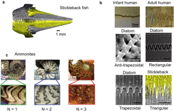
Figure 1-‐‑1| Examples of suture interfaces in nature. a) Suture interfaces in the pelvic assembly of the
stickleback fish that vary in frequency 10, b) first-‐‑order geometric suture interfaces in human skulls,
diatoms, and the stickleback fish 11, c) hierarchical suture interfaces in ammonites 12.
The triangular suture interfaces in the pelvic assembly of the marine three-‐‑spined stickleback fish (Gasterosteus aculeatus) are of interest because they demonstrate geometric variation within a certain structure. In particular, the frequency, amplitude, and amount of interdigitation of the suture interface is observed to vary spatially across the structure. This variation is suggested to allow increased stiffness and load-‐‑bearing support at critical locations where it is needed. 10
Diatoms also exhibit variation in the same structure across species (Figure 1-‐‑1b). They have suture interfaces with a variety of simple geometries, ranging from trapezoidal to rectangular to anti-‐‑trapezoidal 13. These variations in suture interface geometries are the
motivation behind the exploration of mechanical advantages that drive geometric variation.
The intricate suture interface geometries on the ammonites are perhaps the most fascinating of all. The complexity, or order of hierarchy varies across different ammonites (Figure 1-‐‑1c) from simple curves to complex, fractal-‐‑like patterns. In addition, even within a single ammonite, the suture is a three-‐‑dimensional structure that has higher complexity near the surface (Figure 1-‐‑2).
Figure 1-‐‑2| MicroCT image of ammonite shell. a) Three-‐‑dimensional view of ammonite shell, b) Cross-‐‑
sectional view of ammonite shell from the surface to the interior showing the increase in complexity near the surface of the shell.
1.3.2 Function of suture interfaces
In general, suture interfaces are known to provide flexibility to accommodate growth, respiration, or locomotion 14. However, the specific function of suture interfaces, and
why certain suture interfaces possess certain geometries is unclear. For ammonite sutures in particular, the function of suture interface complexity has been debated. The most widely cited explanation is the Buckland hypothesis, which relates complex suture interfaces to higher strength to protect against implosion (15Buckland, 1836). This theory
has been both supported by analysis using mechanical principles 16 and refuted by
empirical evidence analyzing suture complexity of species in relation to the depth at which the ammonite resided 6,17.
Despite the disagreements, it has generally been agreed upon that the different geometries of suture interfaces serve at least a mechanical purpose. As mentioned before, cranial suture interfaces in vertebrates change geometries through growth and development. The easily modifiable cranial suture morphology suggests that it is a mechanical signal that triggers the changes. 14 Thus, this research focuses primarily on
mechanical behavior, but can serve as a gateway to the studies of other properties.
1.3.4 Mechanical behavior of suture interfaces and composites
The mechanical behavior of specific suture interfaces has been studied both
experimentally and through finite element analysis. Experimentally, it has been found that while skulls with suture interfaces are not as strong in bending as skulls without suture interfaces, skulls with suture interfaces have a significant increase in energy absorption 18 and are slightly more compliant 19. In addition, an increase in
interdigitation provides increased strength in three-‐‑point bending 18. The suture
interface of turtle shells demonstrate a nonlinear behavior under three-‐‑point bending— an initial low stiffness regime is followed by a linear, higher stiffness regime when the two sides of the bone meet, lock, and resist further deformation 20. Also, for interfaces in
general, it has been shown that interfacial strength can be enhanced through geometric complexity 21.
Additionally, finite element modeling has provided more insight into the mechanical behavior of suture interfaces. The suture interfaces of lizard skulls were found to play an important role in redistributing strain around the skull without reducing the total strain within the skull 22. Also, increased interdigitation of suture interfaces was found
to correspond with decreased suture strain energy 23.
Though research has been done on the mechanical properties of specific suture
interfaces, a comprehensive, systematic study of the relationship between geometry and mechanical behavior of suture interfaces and composites is needed. There are many challenges to performing mechanical tests on biological samples, including difficulty of sample preparation, and the relationship between geometry and mechanical properties cannot be clearly elucidated due to the heterogeneity and randomness of biological samples. Therefore, the approach presented in this thesis, which utilizes mechanical testing of bio-‐‑inspired 3D-‐‑printed prototypes in combination with finite element and analytical models, acts as a framework for any future study that wishes to determine the relationship between geometry and mechanical behavior of any composite material.
1.3.5 Analytical models
Recently, the first step toward a systematic study of the relationship between geometry and mechanical behavior of sutures has been taken with the development of an
analytical model predicting the strength, stiffness, and toughness of suture interfaces with several types of geometries. The analytical model has been derived for several geometric cases: first-‐‑order triangular suture interfaces, first-‐‑order suture interfaces of arbitrary geometry, and hierarchical suture interfaces. First-‐‑order suture interfaces indicate a single waveform, while hierarchical suture interfaces of higher orders refer to a fractal-‐‑like geometry, where a self-‐‑similar waveform is superimposed on the
waveform of the prior order of hierarchy.4
The analytical models are able to predict mechanical properties of the suture interface given the geometric parameters and basic material properties of the teeth and interface. The models assume linear elasticity and deformable teeth; and the results were verified through finite element analysis. Several key findings resulted from the development of these analytical models. First, the triangular geometry was found to be optimal, in that it is the only geometry with uniform stress distribution in both the teeth and interface when under tension. Therefore, the triangular suture interface optimally distributes the stress across the structure, resulting in higher stiffness and strength relative to other geometries. 4 In addition, the results showed the possibility of nonlinearly amplifying
and tailoring the mechanical behavior of a suture interface through changes in the order of hierarchy 11,12.
From these results, it is evident that suture interfaces have the potential of playing an important role in the amplification and tailorability of mechanical behavior of materials.
2 Triangular suture interfaces
2.1 Introduction
This chapter is motivated by the suture interfaces observed in the pelvic girdle of the stickleback fish (Figure 1-‐‑1a). This particular structure shows suture interfaces where the teeth are triangular and vary in frequency within a single suture structure and also differ for marine and freshwater stickleback fish (Figure 2-‐‑1). This chapter explores the effect on mechanical behavior of this simple change in frequency and aims to
understand why this variation would exist.
Based on the analytical model developed by Li et al.4, the triangular geometry was
determined to the one and only geometry that is able to uniformly distribute stress across the tooth, resulting in higher stiffness and strength. In addition, for the triangular geometry, the relationship between the normal stress and shear stress is dependent only on the tip angle. The stiffness of the resulting suture interface structure was found to be dependent on the volume fraction of the interface, the tip angle, and properties of the constituent materials. For a given volume fraction and set of constituent material
properties, suture interfaces with small tip angles are predicted to have higher stiffness.
The analytical model shows a clear dependence of the stiffness and strength of a triangular suture interface on the tip angle. In order to gain a better understanding of the effect of tip angle on mechanical behavior (stiffness, strength, toughness, failure mechanisms), this chapter shows results from experimental mechanical tests on 3D-‐‑ printed prototypes.
Figure 2-‐‑1| Two-‐‑dimensional morphology of the ventral median suture of bilateral pelvic girdles from marine and freshwater stickleback fish. a Ventral view of three-‐‑dimensional microCT images of the
pelvic girdles (retracted position) from marine (left) and freshwater (right) G. aculeatus with schematic diagram of a two-‐‑dimensional suture model. The marine microCT image is similar to that reported previously (8). Scale bar ~ 1 mm. b-‐‑e, The dorsal to ventral spatial distribution of: b and c, relative amplitude, A/L, (b) and spatial frequency, L/λ, (c), of the median suture in marine and freshwater G.
aculeatus; and d, predicted suture stiffness of both G. aculeatus populations. e, Average stiffness and ID of
four regions in marine and freshwater G. aculeatus. †A: amplitude of a median suture, AB: ascending branch, AP: anterior process, L: total length of pelvis, PP: posterior process, PS: pelvic spine, S: median suture, TG: trochlear joint, λ: width of a suture tooth, g: width of the interphase region between neighboring ventral suture teeth. (Song, in prep)
2.2 Materials and Methods
Bio-‐‑inspired artificial triangular suture joints with three different frequencies were designed using Solidworks. The frequencies of the suture joints were varied by altering the tip angle θ, while maintaining a constant volume fraction of 75% and an interface
width of 0.5 mm. Samples were then fabricated with the Connex500 3D multi-‐‑material printer (Objet Geometries, USA). VeroWhite, an acrylic-‐‑based photo-‐‑polymer, was used for the tooth, TangoPlus, a rubber-‐‑like flexible material, was used for the interface. To test the basic mechanical properties of VeroWhite and TangoPlus, standard ASTM D-‐‑ 638-‐‑V dogbones of each material were individually fabricated. Standard dogbones were oriented at 0˚, 45˚, and 90˚ to test anisotropy. These material properties are used for the theoretical predictions of the various suture joints. Four samples of each frequency of suture joints were tested using a Zwick Mechanical Tester (Zwick Z010, Zwick Roell, Germany) for force-‐‑displacement measurements in conjunction with a video
extensometer and digital image correlation software for local strain measurements. All tests were quasi-‐‑static with a constant strain rate of 0.002 s-‐‑1.
2.3 Results
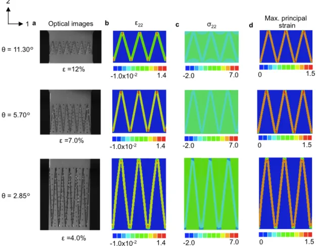
Figure 2-‐‑1 demonstrates the successful fabrication (Fig. 2-‐‑1a) and mechanical testing (Fig. 2-‐‑1b) of 3D-‐‑printed triangular bio-‐‑inspired artificial suture interfaces of varying frequency (θ = 2.85○, 5.70○, 11.30○), which experimentally validate the theoretical
predictions and also provide proof-‐‑of-‐‑concept for rational geometrically-‐‑optimized bio-‐‑ inspired design. Tensile stress versus strain behavior, including Young’s modulus, tensile strength, failure mechanisms, and toughness), are seen to vary dramatically with suture frequency, with Young’s modulus, tensile strength, and toughness increasing nonlinearly with increasing suture frequency (Fig. 2-‐‑1b). The suture interface theory (input parameters; volume fraction of tooth material, tooth angle θ, Young’s modulus of tooth material, Young’s modulus of interface material, shear modulus of interface
material) predicts the experimental data exceedingly well (Fig. 2-‐‑1b). Predictions from the suture interface theory at different material properties show that increasing the stiffness or strength ratios of the interface material to the tooth material results in an increase of the effective mechanical properties for all frequencies. The same effective mechanical property can be achieved with a lower frequency suture interface by utilizing materials of a higher stiffness or strength ratio.
In all cases, the bio-‐‑inspired suture joints exhibit geometrically-‐‑controlled toughening mechanisms leading to non-‐‑catastrophic “graceful failure”. The highest frequency suture interface (θ = 2.85˚) reaches its maximum load-‐‑bearing capacity at a strain smaller than that of the lower frequency suture interface. After reaching its peak, the highest frequency suture joint has a steep drop in load-‐‑bearing capacity. The lowest frequency suture joint (θ = 11.30˚) reaches its maximum load-‐‑bearing capacity at a higher strain and has a more gradual decline in load-‐‑bearing capacity. Failure
mechanisms were observed in situ in Fig. 2-‐‑1d. For θ = 2.85˚, the suture interface fails discretely at an increasingly numbers of locations until the entire interface is
disconnected. For θ = 11.30˚, the initial load pulls the teeth slightly closer together and then interface failure releases this initial tension, and the teeth relax to their initial configuration, resulting in simultaneous failure of many locations across the interface, corresponding to a steeper drop in load-‐‑bearing capacity. Finite element analysis of the suture interfaces (Figure 2-‐‑2) with different frequencies at each of its maximum load-‐‑ bearing capacities show localization of strain at the interface. Also, higher frequency suture interfaces have greater normal stress in the teeth. In addition, maximum
principal strain in the interface is the same for all frequencies at maximum load-‐‑bearing capacity.
Figure 2-‐‑1| Mechanical behavior of artificial bio-‐‑inspired triangular suture interfaces. a, 3D printed
prototypes of triangular suture joints with three different frequencies. b, Stress-‐‑strain behavior of triangular suture joints with three different frequencies. c, Nondimensional stiffness (E/Etooth),
compared to theoretical predictions from the suture interface model at different material properties (Einterface/Etooth = 0.035%, 0.5%, 5%, Sinterface/Stooth = 3.2%, 10%, 20%, and Sinterface/Stooth = 3.2%, 4.0%, 5.0%, for the
stiffness, strength, and toughness comparisons respectively). d, Images showing the deformation of the triangular suture interfaces at corresponding stresses and strains indicated of the tensile stress-‐‑strain curves.
Figure 2-‐‑2| Finite element analysis of triangular suture interfaces at its experimental maximum load-‐‑ bearing capacity. a Images of triangular suture interface prototypes at maximum load-‐‑bearing capacity, b
contours of normal strain in the direction of loading (ε22) c contours of normal stress in the direction of
loading (σ22), d and contours of maximum principal strain.
2.4 Discussion
In the stickleback fish, the tip angle of the triangular suture interfaces are shown to vary from 2θ = 3° to 2θ =180°. From the results shown above, this wide range in tip angle can allow for significant (close to an order of magnitude) local variations in stiffness, strength, toughness, and failure mechanisms. Regions with smaller tip angles were shown to
correlate with regions that need to offer increased mechanical support to the trochlear joints and pelvic spines. Therefore, variation in tip angle is a simple way of changing suture interface properties.
3 Structured general trapezoidal suture interfaces
This chapter was published as an article in the Journal of Mechanics and Physics of Solids in 2014 24.
3.1 Introduction
Geometrically structured interfaces are prevalent throughout nature and give rise to many remarkable mechanical properties in a number of biological materials (25Bruet et.
al., 2008; Dunlop et al., 2011; Y. Li et al., 2011, 2012, 2013a; Weiner and Addadi, 1997; Zhang et al., 2012). For example, both computational 26 and experimental studies
(21Bruck et al., 2004) reveal that geometrically interlocking interfaces enhance interfacial
stiffness and strength, and interface waviness increases resistance to crack propagation
27.
A particularly fascinating example of geometrically structured interfaces is composite suture interfaces. Suture interfaces are mechanical structures often found in biology consisting of compliant, interlocking seams connecting stiffer components 5. In nature, a
wide range of suture interface geometries are observed, ranging from nearly flat suture interfaces in infant human skulls 9 to intricate, fractal-‐‑like designs in ammonites 6.
Suture interface geometries are found to vary within species 5, within a certain structure
across species 10, through evolution 7, or even with development 28. The diverse interface
geometries hint at nature’s ability to utilize a limited set of natural materials to achieve a wide range of properties and functions simply through variation in geometry 29.
The geometry of suture interfaces has been shown, experimentally or through finite element analysis (FEA), to influence mechanical performance. Suture interfaces have been found to increase energy absorption 18, compliance 19, deformability, 30 and
flexibility 14. In addition, suture interfaces were shown to play an important role in the
redistribution of strain in skulls 22. Increased interdigitation in suture interfaces was
found to increase bending strength 18 and decrease suture strain energy 23. These studies
confirm that geometric variation affects the effective mechanical behavior of the suture interface. However, a systematic, comprehensive experimentally-‐‑verified
understanding of the underlying role geometry plays in the overall mechanical behavior, including stiffness, strength, toughness, and failure mechanisms of suture interfaces, is lacking.
Recently, we developed a generalized analytical suture interface model for the case of in-‐‑plane loading of any suture interface with arbitrary geometry verified by finite
element modeling 4,11,31. This model gives analytical solutions for the effective stiffness,
strength, and fracture toughness of suture interfaces with an unbonded tip interface in terms of a set of independent geometric parameters and material properties of the compliant seam and stiffer interdigitating “teeth”. Using this analytical model, it was predicted that the mechanical properties of suture interface systems have a highly nonlinear dependence on geometry and order of hierarchy. In addition, a general trapezoidal suture interface was predicted to possess significantly enhanced stiffness, strength, and fracture toughness relative to a flat interface. For a given set of materials, altering the geometry of the suture interfaces was found to result in a range of values for stiffness, strength, and fracture toughness, demonstrating the possibility of precise tailorability of mechanical properties through geometry.
The objectives of this study are threefold. On the theoretical side, the analytical model presented in Li et al. (2013) is extended to include the behavior of suture interfaces with bonded tip interfacial layers. In nature, suture interface geometries typically consist of initially fully bonded interfaces, and therefore the effect of a fully bonded interface on the effective mechanical behavior is determined. Experimentally, the relationship between geometry and mechanical behavior of general trapezoidal suture interfaces is systematically explored, through the design and fabrication of bio-‐‑inspired prototypes via 3D printing and mechanical experiments. Previously, we have employed 3D printing fabricate co-‐‑continuous composite structures with enhancements in stiffness, strength, and energy dissipation (32) and subsequently this fabrication method has been
rapidly emerging as a means to create physical prototypes of material structures to explore the roles of geometry and materiality on properties and performance (33-‐‑ 35). Here, we exploit multi-‐‑material 3D printing to construct physical prototypes of a
range of suture waveforms with soft, compliant interface layers adhering stiffer skeletal teeth and reveal the ability to tune the mechanical behavior (stiffness, strength,
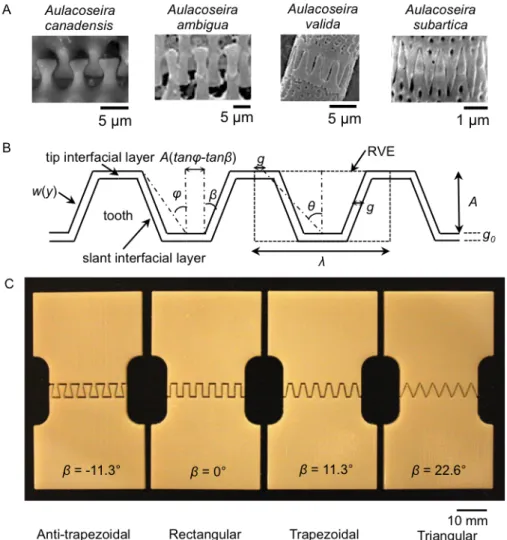
toughness, deformation and failure mechanisms) through the interplay between geometry and materiality. Four categories of bio-‐‑inspired representative periodic geometries that resemble suture interfaces in the linking girdles of diatoms (Figure 3-‐‑ 1A) are chosen: anti-‐‑trapezoidal, rectangular, trapezoidal, and triangular (Figures 3-‐‑1B and 3-‐‑1C). These four geometries were designed to possess the same tooth volume fraction and wavelength, and the same interfacial layer thickness and material combination. Hence, the only difference is the shape. Specifically, we focus on three design parameters, which include bonded vs. unbonded flat interfacial layer at the peaks of the teeth, tooth tip angle (θ), and a shape factor β (Figure 3-‐‑1B) defined by Li et al. (11) to distinguish tooth shape. This study enables the extraction of design principles
from the theoretical and experimental results for the design of new material interfaces with tailored mechanical behavior.
Figure 3-‐‑1| Inspiration and design of bio-‐‑inspired suture interfaces. A) Examples of suture interfaces in
nature (Manoylov et. al, 2009; Bahls et. al, 2009; Genkal and Popovskaya, 2008), B) Schematic of general trapezoidal suture interfaces and defining geometric parameters, C) optical images of bio-‐‑inspired 3D printed suture interface prototypes.
3.2 Materials and methods
Bio-‐‑inspired suture interfaces with and without bonded tip regions, with different tip angles, and with different geometries were designed within Solidworks (Dassault Systemes, 2013) and fabricated (Figure 3-‐‑1C) with an Objet Connex500 3D multi-‐‑
material printer (Stratasys Ltd., USA). VeroWhite, an acrylic-‐‑based photo-‐‑polymer, was used for the teeth, and TangoPlus, a rubber-‐‑like compliant material, was used for the interfacial layers. For each set of designs, the volume fraction and interface width were held constant. Four samples of each design were tested and all errors reported represent standard deviation. The resolution of the 3D multi-‐‑material printer is 16 micrometers in the z-‐‑direction (thickness) and 42 micrometers in the x and y-‐‑direction. Therefore the
smallest feature size of the prototypes is designed to be at least an order of magnitude greater than the resolution to minimize any effects of the manufacturing process on the mechanical behavior.
To test the basic mechanical properties of VeroWhite and TangoPlus, standard ASTMD-‐‑ 638-‐‑V dogbones of each material were individually fabricated. The Young’s moduli of TangoPlus and VeroWhite were determined to be 0.63 +/-‐‑ 0.02 MPa and 2.0 +/-‐‑ .09 GPa, respectively. The tensile strength of TangoPlus and Verowhite were determined to be 1.1 +/-‐‑ 0.2 MPa and 43.7 +/-‐‑ 0.3 MPa, respectively (Figure 3-‐‑2A). In addition, in order to test the pure tensile and simple shear strength of the interfacial layer, samples with a flat interface and a simple shear interface were designed and fabricated (Figure 3-‐‑2B). Due to the nature of the 3D printing, and recognizing the presence of a graded material region in between the tooth material and the interfacial layer, two interface widths of 0.5 mm and 1 mm were used in the suture prototype designs, and the tensile and shear strength for each interface width was tested. The tensile strength is determined to be 1.8 +/-‐‑ 0.94 MPa and 0.97 +/-‐‑ 0.41 MPa for an interface width of 0.5 mm and 1 mm,
respectively. The shear strength is determined to be 1.4 +/-‐‑ 0.11 MPa and 1.1 +/-‐‑ 0.16 MPa for interfacial layers of 0.5 mm and 1 mm, respectively. For both interface widths, the interfaces exhibit nonlinear elastic behavior until initial failure, at which point plastic deformation occurs until catastrophic failure. Failures were found to be cohesive failures within the interfacial layer. The cohesive failure was verified through SEM of 3D-‐‑printed suture interface prototypes post-‐‑failure (36). These material properties were
used for the analytical predictions of the various suture interfaces. To account for the different properties between the two interface widths, the experimentally determined material properties corresponding to the interface width are utilized in analytical predictions to represent the tensile strength of the interface material.
Figure 3-‐‑2 | Mechanical properties of 3D-‐‑printed material under uniaxial longitudinal tension. A) True
stress-‐‑true strain curves of interfacial layer (TangoPlus) and tooth material (VeroWhite), B) flat and shear interface specimen and experimental stress-‐‑strain behavior. Scale bars are 10 mm, and error bars indicate standard deviation.
Four samples of each suture interface design were tested using a Zwick Mechanical Tester (Zwick Z010, Zwick Roell, Germany) for force-‐‑displacement measurements in conjunction with a video extensometer and digital image correlation (DIC) software (VIC2D) for global and local strain measurements and contours in the suture area (including both teeth and interfacial layers). All experiments were quasi-‐‑static with a constant strain rate of 0.002 s-‐‑1. Engineering stress was calculated from force
measurements, while engineering strain was calculated from local displacement measurements from DIC.
3.3 Theory
The geometry of a general trapezoidal suture interface can be described by five
independent parameters: the wavelength, λ, the tooth amplitude, A, the shape factor, 𝛽, the slant interface width, g, and the tip interface width, g0 (Figure 1B). 𝛽 determines the shape of the suture interface: anti-‐‑trapezoidal when −𝜃 < 𝛽 < 0, rectangular when 𝛽 = 0, trapezoidal when 0 < 𝛽 < 𝜃, and triangular when 𝛽 = 𝜃, (Li et al., 2013). The frequency of the waveforms can be quantified by the nondimensional tooth tip angle, θ, defined as tan 𝜃 =!!!!!! . For the same tooth volume fraction, 𝜃 corresponds to the aspect ratio, !!, of a representative volume element. The tooth angle, 𝜑, is defined as tan 𝜑 =(!"# !!!"# !)! .
In the following section, the analytical models derived via the principle of
complementary virtual work presented in Li et al. (2013a) are expanded to derive the in-‐‑ plane tensile modulus, tensile strength, and fracture toughness of suture interfaces with a bonded interfacial layer at the tip region. In all derivations, the tooth and interfacial layers are assumed to be perfectly bonded over the entire interface. Both interface and tooth phases are taken to be homogeneous, linear elastic and isotropic. The slanted and tip interfacial layers are considered to have no direct interaction (Figure 3-‐‑3A). These assumptions are appropriate for the prediction of stiffness, strength, and toughness for the 3D-‐‑printed suture interface prototypes: the 3D-‐‑printed materials are shown
experimentally to be isotropic and homogeneous and the cohesive failure of the interfacial layer closely approximates a perfectly bonded tooth and interfacial layer.
Figure 3-‐‑3 | Schematic of mechanical model. A) Diagram showing geometry of suture interface with
unbonded vs. bonded tip interface, and the corresponding stresses under uniaxial longitudinal tension, B) schematic of expected mechanical behavior of suture interface with un-‐‑bonded and bonded tip interface under uniaxial longitudinal tension, where 𝝈ftip and 𝑬tip are the strength and stiffness from the bonded tip
interface, 𝝈fnotip and 𝑬notip are the strength and stiffness from the slant interface, and S’ is the post-‐‑peak
failure process.
3.3.1 In-‐‑plane tensile modulus
The suture interface under tension due to far-‐‑field loading, 𝜎, perpendicular to the suture axis, is balanced by stress across the base of the tooth, 𝜎!"#$, and the normal
stress across the tip region, 𝜎!"#, as shown in Figure 3A, with the relationship
𝜎 = 𝜎!"#$𝑡!"#$ 𝜆 + 𝜎!"#
𝑡!"#
𝜆 (1)
where 𝑡!"#$= 2𝐴 tan 𝜑 and 𝑡!"# = 𝜆 − 2𝐴 tan 𝜑 are the lengths of the base and gap
between teeth, respectively; and A and λ are the amplitude and wavelength of the tooth geometry, respectively.
The tension at the base of the tooth, 𝜎!"#$, is further balanced by the interfacial shear
stress, 𝜏!, and interfacial normal stress, 𝜎!, and the normal stress across the tip, 𝜎!"#, as
shown in the free-‐‑body diagram in Figure 3A. Force equilibrium in the x and y directions yields
𝜎! = 𝜏! tan 𝛽 (2a) and
𝜎!"#$tan 𝜑 = 𝜎!"# tan 𝜑 − tan 𝛽 + !!
!"#!!. (2b)
3.3.1.1 Rigid tooth model (RTM)
First, we consider the case of the Rigid Tooth Model (RTM) where the teeth are assumed to be rigid. The total strain energy, 𝑈!,!"# due to applied tension across the
suture can be expressed as
𝑈!,!"# =!!𝐸!"#𝜀!𝑉, (3a)
where 𝐸!"# denotes the effective modulus of the suture interface with tip material, 𝜀 is
the effective axial strain across the entire suture area, and 𝑉is the volume of the entire suture, and 𝑉 = (𝐴 + 𝑔!)𝜆.
𝑈!,!"# can also be expressed in terms of the interfacial layer contributions
𝑈!,!"# = !!𝑉!"#$% !! ! !!!" + !! ! !! + ! !𝑉!"# !!"# ! !!!" , (3b)
where 𝑉!"#$% is the volume of the slanted region of the interface, 𝑉!"# is the volume of the
tip region, 𝐸!!" is the plane strain tensile modulus of the interfacial material, and 𝐺! is
the shear modulus of the interfacial material.
By equating Eq. (3a) and Eq. (3b), an expression for the effective stiffness, 𝐸!"#, can be
derived.
For a small elastic deformation, δ, equilibrium and kinematic analysis of the slanted and tip interface regions yield
𝜎!"# = 𝐸!!"𝜀!"# = 𝐸!!" !!! , (4a)
𝜏! = 𝐺!𝛾!"#$% = 𝐺! !! . (4b)
By substituting Eq. (2) and Eqs. (4a, b) into Eqs. (3a,b), the effective tensile modulus of a suture interface with a bonded tip area and rigid teeth is derived to be
𝐸!"#,!"# = 𝐸!"#$%+ 𝐸!"#, (5a) where 𝐸!"#$% = 𝑓! !! ! !! ! !!!"tan!𝛽 + 𝐺! ; (5b) 𝐸!"# = 𝑓!𝐸!!"(!! !) !, (5c) and where 𝑓! and 𝑓! are the volume fractions of the slant interfacial layer and tip
interfacial layer in the suture area, respectively; and 𝑓! = !!"#$%! = 1 −!!!, and 𝑓! = !!"#
! = !!!"#!!
! !!!! .
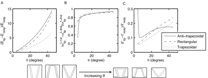
The bonded tip region provides an increase in stiffness that can be expressed as the ratio of 𝐸!"#$% to 𝐸!"#, 𝑅!:
𝑅! = !!"# !!"#$%= !! !! ! !! !!!" !! ! ! !"#!!!!!!" !! . (5d)
As will be seen later, this increase in stiffness can be significant. For example, for the case of 𝜃 = 22.6° and 𝛽 = 0° (a rectangular suture), 𝑅! = 0.71 meaning a 71% increase
in stiffness.
3.3.1.2 Deformable Tooth Model (DTM)
A rigid tooth assumption is reasonable when the tooth modulus, 𝐸! ≥ 1000 𝐸!!".
However, in general, the deformation of the teeth can add compliance and can be a significant contribution to the strain energy. Therefore, using a deformable tooth model, the total strain energy, 𝑈!,!"#, of the suture interfaces is from the slant interface, the tip
interface, and the teeth. 𝑈!,!"# = !! ! !! !!"#,!"# = 𝑈!"#$%+ 𝑈!"#+ 𝑈!""!! (6a) where 𝑈!"#$% = !!𝑉!"#$% !! ! !!!" + !! ! !! ; 𝑈!"# = !!𝑉!"# !!"# ! !!!" ; (6b) 𝑈!""!! = 2 !!! !! !! ! ! 𝑤 𝑦 𝑑𝑦 ,
where w(y) is the profile of the slant edge, given by (Li et al., 2013)
𝑤 𝑦 = 𝑦 𝑡𝑎𝑛𝛽 + 𝐴 𝑡𝑎𝑛𝜑 − 𝑡𝑎𝑛𝛽 , 0 ≤ 𝑦 ≤ 𝐴, 0 ≤ 𝑤 𝑦 <!"!
! , (6c)
and where 𝜎!! 𝑦 is the stress distribution in the tooth, given by
𝜎!! 𝑦 = [!!"#$ !"# !!!!"# (!"# !!!"# !)]!!! (!"# !!!"# !)!!"#
! !"# !!! (!"# !!!"# !) . (6d)
The full expressions and derivations are shown in the Appendix.
For a small elastic deformation, 𝛿, assuming the tip deforms by 𝛿! and the teeth deform
by 𝛿!, where 𝛿 = 𝛿!+ 𝛿!, equilibrium and kinematic analysis of the slant and tip
interface yields 𝜎!"# = 𝐸!!"𝜀 !"# = 𝐸!!" !!!! ; (7a) 𝜎!"#$ = 𝐸! 𝜀!""!! = 𝐸! !! ! ; (7b)