Augmenting Datum Flow Chain Method to Support the Top-Down
Design Process for Mechanical Assemblies
by
Gaurav Shukla
B. Tech., Mechanical Engineering Indian Institute of Technology at Kanpur, 1999 Submitted to the Department of Mechanical Engineering In Partial Fulfillment of the Requirements for the Degree of
Master of Science in Mechanical Engineering at the
MASSACHUSETTS INSTITUTE OF TECHNOLOGY
June 2001
( 2001 Massachusetts Institute of Technology All rights reserved
Signature of Author.
Certified by
Department df Mechanical Engineering May 11, 2001
Dr. Da 'el E. Whitney Senior Research Scientist Center for Technology, Policy and Industrial Development Lecturer, Department of Mechanical Engineering Thesis Supervisor
Accepted by_
Prof. Ain A. Sonin Chairman, Departmental Committee on Graduate Students
MASSACHUSETTS INSTITUTE
OF TECHNOLOGY
Augmenting Datum Flow Chain Method to Support the Top-Down
Design Process for Mechanical Assemblies
by
Gaurav Shukla
Submitted to the Department of Mechanical Engineering In Partial Fulfillment of the Requirements for the Degree of
Master of Science in Mechanical Engineering
Abstract
The aim of this thesis is present tools which support the top-down design process for assemblies
by analyzing the locating scheme or constraint structure of assemblies in absence of detailed
level part geometry. The top-down design process has received attention both in academia and industry. However, there have been few analytical tools to support it. The bottom-up approach supported by CAD systems is good for detailed level design of a single part. The representation and manipulation of assemblies involves structural and spatial relationships between individual parts at a higher level of abstraction than the representation of single parts. This thesis uses the Datum Flow Chain (DFC) for symbolic representation of mechanical assemblies and screw theory for representation of constraints between two parts. DFC captures the design intent by recording location scheme of assemblies. Screw theory can represent constraints in three dimensions.
This thesis presents the design steps and corresponding analytical tools for a top-down design process in a logical progressive way. The approach of bottom-up process supported by CAD systems is compared all along the presentation. A method to generate the screw theory representation of relative constraints between two arbitrary contacting surfaces is presented first.
A procedure has been outlined to generate the screw representation of an assembly feature
constructed by several contacting surface pairs. These tools can be used to construct screw theory representation of an arbitrarily complex assembly feature. A method of finding the constraint properties of assemblies, which uses screw theory, is presented next. The method of motion analysis can find under-constraints for all assemblies. This can be used for analysis of instantaneous kinematics of a general mechanism as well. Finding over-constraints in an assembly is a separate problem and it requires different procedure of analysis than motion analysis. This thesis presents a method of finding over-constraints of assemblies. Quantitative information about over-constraint of all assemblies may not be found in cross-coupled assemblies. Motion and constraint analyses can help assembly designers in evaluating the nominal design.
A method to calculate the sensitivity of the location of a part due to variation in the location of
an assembly feature is presented next. This method uses the screw theory representation of constraints and information about location of assembly features. Clearance is introduced on
bi-directional assembly features to reduce the probability of interference but it introduces uncertainty in the location of parts. A method is proposed to analyze uncertainty in the location of parts due to clearance on the size dimensions of assembly features. These analysis tools can be used to check robustness of the nominal design. A classification of assemblies based upon constraint properties is presented next. This classification relates properties of constraint structure of assemblies to design context. Finally, this thesis lays out a coherent scheme of design steps forming a procedure for designing mechanical assemblies in a top-down fashion.
Thesis Supervisor: Daniel E. Whitney Title: Senior Research Scientist
Acknowledgements:
First I would like to thank my advisor Dr. Daniel Whitney for giving me the opportunity to conduct this research. I acknowledge the freedom that he gave me in finding the research topics and pursuing them. I must acknowledge him for his mentorship as well. I cannot imagine, at this moment, that my research could have evolved the way it has in absence of his guidance. I think I inherited from him various aspects of his personality during our discussions in last two years.
I must thank Dr. Whitney for providing me various opportunities to visit industry and to interact
with engineers there. I would like to thank Dr. Nancy Wang in Knowledge-Based Engineering at Ford Motor Co. who helped me in understanding CAD systems better. Craig Moccio, Mike Trygar and Chuck Voelker in Total Vehicle Geometry group at Ford gave me practical problems to validate our theory. I must thank Dr. Chris Magee for helping me in finding the right audience within Ford. Jack Chung and Jeff Wang at Structural Dynamics Research Corporation helped me in focusing on the loose aspects of our research by their constructive criticism. I should also acknowledge the support Dr. Allan Jones at Boeing provided me by answering my questions.
It is impossible not to mention friends that I made at MIT. It is because of them I would remember this place the most. I thank Alberto, Gennadiy, Fredrik and Pung for providing a stimulating work environment. This list will remain incomplete if I don't thank Shivanshu for putting up with me in the same apartment for two years.
I would also like to acknowledge the support that my parents provided throughout the period of
my studies. It is impossible for me to think that I could have thought anything worthwhile without their support.
This material is based upon work supported by National Science Foundation (NSF) under Grant no. DMI-9610163 and Ford Motor Company. Any opinions, findings and conclusions or recommendations expressed in this material are those of author and do not necessarily reflect the views of the NSF or Ford Motor Company.
Contents
ABSTRACT 3
ACKNOWLEDGEMENTS 5
CONTENTS 7
LIST OF FIGURES AND TABLES 11
1 INTRODUCTION 17
1.1 Motivation 17
1.2 Goal of Research 18
1.3 Thesis Overview 19
1.3.1 Top-Down Design Process for Mechanical Assemblies 19
1.3.2 Bottom-Up Design Process for Mechanical Assemblies 20
1.3.3 Comparison between the Top-Down and the Bottom-Up Methods 21
1.3.4 The Organization of the Thesis 22
2 DATUM FLOW CHAIN (DFC) 23
2.1 Datum Flow Chain 24
2.1.1 Background and Prior Work 25
2.1.2 Properties of DFC 26
2.1.3 Mates and Contacts 28
2.1.4 DFC and Assembly Architecture 28
2.2 CAD Systems and Assembly Analysis during Conceptual Stage Design 30
2.3 Conceptual Stage Design of Mechanical Assemblies using DFC Approach and the 32
same using CAD Systems
2.4 Subsequent Design Steps in Top-Down and Bottom-Up Approaches 33
2.5 Summary 34
3 BUILDING AN ASSEMBLY FEATURE 35
3.1 Construction of an Assembly Feature 35
3.1.1 Twist and Wrench Representation 37
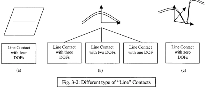
3.1.2 Basic Surfaces and Types of Contacts 38
3.1.3 Basic Surface Contacts and their Twist-Matrices 42
3.1.5 Examples 48
3.2 Identification of Chain of Mates in CAD 51
3.2.1 TTRS 53
3.2.1.1 Definitions 53
3.2.1.2 Analogy between TTRS and Screw Representation of Contacting Surface Pairs 54
3.2.1.3 Identification of Chain of Mates in TTRS 56
3.2.1.4 Inadequacy of the Process of Identifying and Analyzing the Independent Loops 59 in TTRS
3.3 Comparison between the Feature-Based Approach of Top-Down Method and 60
Feature Recognition Approach of Bottom-Up Method
3.4 Summary 61
4 MOTION AND CONSTRAINT ANALYSIS 63
4.1 Graphical Technique for Evaluation of Constraint Properties 64
4.1.1 Previous Work 64
4.1.2 Graphical Representation of DFC 66
4.1.3 Motion Analysis for A Part (Evaluation of Under-Constraints) 67
4.1.3.1 Constructing the Paths for Motion Analysis 67
4.1.3.2 Constructing the Effective Twist-Matrix of the Paths 72
4.1.3.3 Intersecting the Effective Twist-Matrices of the Paths 74
4.1.3.4 Cross Coupling (Dependent Degrees of Freedom) 74
4.1.4 Comparison of the Method of Motion Analysis 82
4.1.5 Constraint Analysis for A Part (Evaluation of Over-Constraints) 91
4.1.6 Examples 94
4.1.7 Limitations of Motion and Constraint Analysis in the Context of Assembly 103
Problems
4.2 Constraint Analysis in CAD System 104
4.3 Comparison of the Constraint Analysis in Top-Down and Bottom-Up Approaches 105
4.4 Summary 106
5 VARIATION AND CONTRIBUTION ANALYSIS 107
5.1 Connective Model of Assemblies 108
5.2 CAD Model of Assemblies 111
5.2.1 World Model 111
5.2.2 Surface-Constrained Model 111
5.2.3 Variation Analysis using CAD Assembly Models 112
5.2.4 Tolerance Allocation 113
5.3 Comparison between the Top-Down and Bottom-Up Assembly Models 115
5.4 Contribution Analysis for Location of Parts in an Assembly 116
5.4.1 Approach of Modeling Variation in Assembly Feature Location 117
5.4.2 Sensitivity in the Part Location to the Variation in Assembly Feature Location 117
5.4.3 Examples 123
5.4.4 Facts of Contribution Analysis 128
5.5 Summary 129
6 UNCERTAINTY DUE TO DESIGN-IN-CLEARANCE 131
6.1 Design-in-clearance and Size Variations in Top-down Design Process 132 6.1.1 Design-in-clearance and Uncertainty in the Location of Assembly Features 132
6.1.2 Design-in-Clearance and Multiple Tolerance Chains 134
6.1.3 Modeling Uncertainty in Assembly Feature Location due to Design-in-Clearance 136
6.1.4 Analyzing Uncertainty in the Location of Parts due to Design-in-Clearance 137
6.1.4.1 Analysis of Design-in-clearance in Properly Constrained Assemblies 138
6.1.4.1.1 Statistical Simulation of Uncertainty in Properly Constrained Assemblies 140
6.1.4.2 Analysis of Design-in-clearance in Over-Constrained Assemblies 144
6.1.4.2.1 Statistical Simulation of Uncertainty in Over-Constrained Assemblies 144
6.2 Size Tolerance in Bottom-Up Design Process 150
6.3 Comparison between the Size Variation Analysis Approach of Top-Down Method 152
and that of Bottom-Up Method
6.4 Summary 152
7 CLASSIFICATION OF ASSEMBLIES 155
7.1 Previous Work 156
7.2 Classification of Mechanical Assemblies 156
7.2.1 Under-Constrained Assemblies 157
7.2.3 Over-Constrained Assemblies 158
7.2.3.1 Over-Constraint Needed for Function 158
7.2.3.2 Over-Constraint Needed for Assembly 160
7.2.3.3 Over-Constraint as Mistake 161
7.3 Summary 161
8 DESIGN PROCESS & DETECTION OF MISTAKES 163
8.1 Design Procedure 164
8.1.1 Nominal Design Phase 164
8.1.1.1 Identification of Key Characteristics 164
8.1.1.2 Selection of a Conceptual Framework of the Design (Making a DFC) 164
8.1.1.3 Selection or Construction of the Assembly Features (Realizing the DFC) 165
8.1.2 Constraint Analysis Phase 166
8.1.2.1 Motion & Constraint Analysis (Checking DFC) 166
8.1.2.2 Making Corrections in DFC 167
8.1.2.3 Identification and Selection of Assembly Sequences 168
8.1.2.4 Detection of KC Conflict 168
8.1.3 Variation Design Phase 169
8.1.3.1 Checking Robustness of the DFC 169
8.1.3.2 Allocating tolerances to the KCs and to the Mates 169
8.1.3.3 Variation and Contribution Analysis 170
8.2 Meeting Assembly Tolerances 172
8.2.1 Deterministic Coordination 172
8.2.2 Statistical Coordination 172
8.2.3 No Coordination 174
8.3 Summary 174
9 CONCLUSION AND FUTURE WORK 175
9.1 Review and Contribution 175
9.2 Scope for Future Research 179
REFERENCES 181
APPENDIX A 189
List of
Figures:
Fig. 1-1: Top-Down Design Process 20
Fig. 1-2: Bottom-Up Design Process 20
Fig. 2-1: DFC 27
Fig. 2-2: Facilities Offered by Turnkey CAD Systems 31
Fig. 3-1: Square-Peg in Square-Hole 36
Fig. 3-2: Different type of "Line" Contacts 39
Fig. 3-3: Cylinder on Plane 43
Fig. 3-4: Wrench-Matrix of a Point Contact 45
Fig. 3-5: Two-Dimensional "Line" Contact 45
Fig. 3-6: Three-Dimensional "Line" Contact 47
Fig. 3-7: Square Peg in a Square-Hole Assembly Feature 49
Fig. 3-8: Pin-Slot Assembly Feature 50
Fig. 3-9: Prismatic Pair 50
Fig. 3-10: Variation in Prismatic Pair 54
Fig. 3-11: Motions for Cylinder on Plane Contacting Pair 55
Fig. 3-12: TTRS and Assembly Graph 58
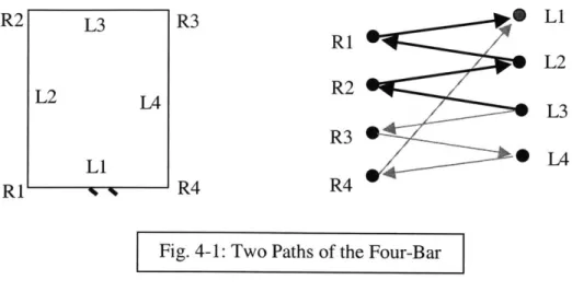
Fig. 4-1: Two Paths of the Four-Bar 67
Fig. 4-2: Serial Path 68
Fig. 4-3: Path with a Parallel Branch 69
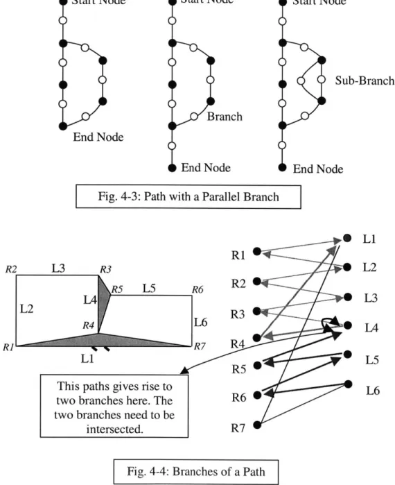
Fig. 4-4: Branches of a Path 69
Fig. 4-5: Path as a Parallel Branch 70
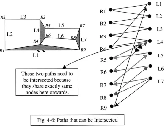
Fig. 4-6: Paths that can be Intersected 70
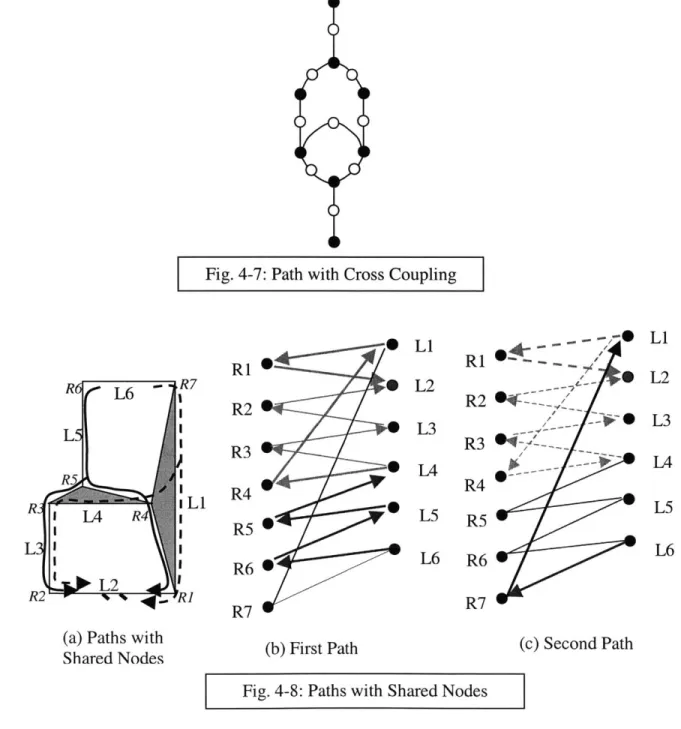
Fig. 4-7: Path with Cross Coupling 71
Fig. 4-8: Paths with Shared Nodes 71
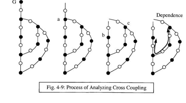
Fig. 4-9: Process of Analyzing Cross Coupling 75
Fig. 4-10: Velocity Components at the Origin of Assembly Feature 77
Fig. 4-11: Path as a Parallel Branch 83
Fig. 4-12: Two DOF Manipulator 84
Fig. 4-14: Method of Finding Over-Constraints: A Set-Theory Analogy 91
Fig. 4-15: Two Plates Joined by Four Features 94
Fig. 4-16: Over-Constraint 96
Fig. 4-17: Parallelogram Mechanism 97
Fig. 4-18: Paths for "L2" and "L4" 98
Fig. 4-19: Paths for "L4" when "L2" is locked 99
Fig. 4-20: Parallel Manipulator 102
Fig. 5-1: Three Parts Joined by a Connective Assembly Model 109
Fig. 5-2: An Assembly of Three Parts in a World Coordinate Frame 109
Fig. 5-3: A Surface-Constrained Assembly Model of Two Parts 112
Fig. 5-4: A Connective Assembly Model of Two Parts 115
Fig. 5-5: Pin in a Slot Assembly Feature 117
Fig. 5-6: Multiple Chains on Part-Feature Diagram 120
Fig. 5-7: Velocity Components at the Origin of Assembly Feature 120
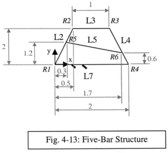
Fig. 5-8: A Five-Bar Linkage 123
Fig. 5-9: Two Plates 123
Fig. 5-10: Variation in the Five-Bar Linkage 126
Fig. 6-1: Unidirectional Constraint 133
Fig. 6-2: Bi-directional Constraint 133
Fig. 6-3: Properly Constrained Assembly 134
Fig. 6-4: Over-Constrained Assembly 134
Fig. 6-5: Over-Constrained Assembly 135
Fig. 6-6: Properly Constrained Assembly 135
Fig. 6-7: Square Peg in Square Hole 136
Fig. 6-8: Design-in-Clearance in Over- and Properly Constrained Assemblies 139
Fig. 6-9: Properly Constrained Assembly 141
Fig. 6-10: Uncertainty in X-location (Properly Constrained Assembly) 143
Fig. 6-11: Uncertainty in 0 -location (Properly Constrained Assembly) 143
Fig. 6-12: Ambiguous Tolerance Chains for Over-Constrained Assemblies 145
Fig. 6-13: Ambiguous Tolerance Chains for Over-Constrained 146
Fig. 6-15: Multiple Tolerance Chains 148
Fig. 6-16: Uncertainty in X-location (Over-Constrained Assembly) 150
Fig. 7-1: Simple Assembly Classification 157
Fig. 7-2: Classification of Assemblies 160
Fig. 8-1: Design Process Chart 171
Fig. 8-2: Classification of Techniques of Achieving Tolerance Specifications 173
Fig. 9-1: Top-Down Design Process 178
Fig. 9-2: Bottom-Up Design Process 178
Fig. A-1: Any Surface with Any Surface 190
Fig. A-2: Any Surface with Helical Surface 190
Fig. A-3: Any Surface with Surface of Revolution 191
Fig. A-4: Any Surface with Cylindrical Surface 191
Fig. A-5: Any Surface with Planar Surface 191
Fig. A-6: Any Surface with Spherical Surface 192
Fig. A-7: Helical Surface with Helical Surface 192
Fig. A-8: Helical Surface with Surface of Revolution 193
Fig. A-9: Helical Surface with Cylindrical Surface 193
Fig. A-10: Helical Surface with Planar Surface 193
Fig. A-11: Helical Surface with Spherical Surface 194
Fig. A-12: Surface of Revolution with Surface of Revolution 194
Fig. A-13: Surface of Revolution with Cylindrical Surface 194
Fig. A-14: Surface of Revolution with Planar Surface 195
Fig. A-15: Surface of Revolution with Spherical Surface 195
Fig. A-16: Cylindrical Surface with Cylindrical Surface (Unidirectional Line Contact) 195
Fig. A-17: Cylindrical Surface with Cylindrical Surface (Unidirectional Point Contact) 196
Fig. A-18: Cylindrical Surface with Cylindrical Surface (Bi-directional Contact) 196
Fig. A-19: Cylindrical Surface with Planar Surface 196
Fig. A-20: Cylindrical Surface with Spherical Surface (Unidirectional Contact) 196
Fig. A-21: Cylindrical Surface with Spherical Surface (Bi-directional Contact) 197
Fig. A-22: Planar Surface with Planar Surface 197
Fig. A-24: Spherical Surface with Spherical Surface (Unidirectional Contact) 198
Fig. A-25: Spherical Surface with Spherical Surface (Bi-directional Contact) 198
Fig. A-26: Wrench for a Point Contact between An Edge and A Surface 198
Fig. B-1: Properly Constrained Assembly 202
List of Tables:
Table 3-1: Surface-to-Surface Contacts 40
Table 3-2: Changing and Unchanging Vectors for "Cylinder on Plane" Assembly Feature 56
Table 3-3: Twist and Wrench Directions for "Cylinder on Plane" Assembly Feature 56
Table A-1: Surface-to-Surface Contacts 189
Table A-2: Edge-to-Surface Contacts 199
Chapter 1: Introduction
1.1 Motivation:
Now, the customers are being given more importance during the design activities. Cost used to be the most important factor of consideration during design of mechanical assemblies but now quality assumes greater significance and reduction in cost is given second priority. Delivering quality requires more attention to what customer wants and translating the customer needs in terms of design requirements. Several researchers [Ulrich and Eppinger, Pahl and Beitz, Suh] emphasize a top-down or requirements-driven design process. [Whitney, Mantripragada, Adams and Rhee, 1999] presented the different phases of a top-down design process for mechanical assemblies. The top-down design process relates customer requirements to the concept and details of the design. It starts with the customer requirements and proceeds systematically to create functional concepts, physical embodiments of these concepts and then decompositions of the main embodiments into smaller and smaller assemblies, sub-assemblies and finally individual parts. It is argued that the top-down design process can reduce the design time and it can avoid potential mistakes during initial conceptual design phase.
Geometric reasoning is one of the most important connections between design and manufacturing. Since the top-down design process calls for the attention of the design team to geometric reasoning in the initial phase of design, it does make the design team more focused towards potential manufacturing problems. Current computer-aided design (CAD) systems are part centric (i.e. The CAD systems do not provide functionality for making assembly level design decisions before filling up the details of the parts). Intelligent CAD systems must support a top-down design process. To support the top-down design process a CAD system need to have functionality for representation of assembly models without the detailed level part design. It should be able to reason in the domain of geometry, handle geometric constraints and satisfy these constraints in an appropriate, complete and unambiguous manner. There exist a need to extend the geometric modeling technology to represent assemblies of parts, since most engineering problems are solved by assemblies rather than single parts.
The representation and manipulation of assemblies involves structural and spatial relationships between individual parts at a higher level of abstraction than the representation of single parts. Such a representation must support association of form features, mating surfaces involved in kinematic connections and determination of degrees of freedom from the mating conditions. Additionally, to support manufacturing, design tools must provide support for representation of tolerances, interference checking and tolerance allocation.
The top-down design can lead to the greater level of customer satisfaction. So far, there have been very few analytical tools that can support the top-down design process which requires analysis tools to evaluate certain design decisions in absence of details of geometry. Mechanical assemblies, where geometrical locations of different parts are important, are main focus of this research. This piece of work focuses on laying out a way to design mechanical assemblies using a top-down design process right from the conceptual stage till the stage of variation analysis. All along the description the analytical tools, which can support a top-down design environment for mechanical assemblies, are discussed. The approach of the bottom-up design process and the tools available for analysis are also discussed to highlight the contribution of this research.
1.2 Goal of Research:
The ultimate goal of this research is to develop a CAD system that supports a top-down designing environment for mechanical assemblies. It should start from a sketcher where the designers can play with several initial concepts. There should be a user-friendly interface to convert the data in the concepts in terms of physical relationships between parts (assembly features) to a schematic form (DFC). There need to be analysis tools to check the various concepts at this stage itself. Analysis tools to carry out the robustness check of assembly level dimensions against part level variations are also required. After this, the sub-assemblies could be sourced out to different design teams for similar exercises. Since all the interfaces among sub-assemblies are coming from the top, there cannot be any problem of co-ordination as long as the databases are shared among different design teams. This thesis is a step towards this goal. It provides foundation to some of the basic analysis techniques that need to be supported.
1.3 Thesis Overview:
This section presents a brief overview of the top-down and bottom-up design processes. A comparison between the two processes is also presented. The organization of this thesis is presented in the final sub-section.
1.3.1 Top-Down Design Process for Mechanical Assemblies:
Fig. 1-1 summarizes the steps of the top-down design process (the boxes in thick borders shall be discussed later in the chapters of the thesis). The top-down design process begins with customer requirements. Customer requirements are translated into key engineering requirements
(Key Characteristics or KCs) and some concepts are chosen to fulfill the KCs.
The next step is to layout the concepts in terms of the geometric reasoning among sub-systems.
A methodology to capture the design intent called Datum Flow Chain (DFC) was introduced by
[Mantripragada and Whitney, 1998]. It provides a method, together with a vocabulary and a set of symbols, for documenting a location strategy for the parts and relating that strategy explicitly to the achievements of customer requirements.
The next step becomes identifying the assembly features which will realize the connections between parts. The assembly features can be picked off the shelf (from a library) or they can be built from basic surfaces. The assembly features constrain relative degrees of freedom between parts. It is important to understand how one can build new assembly features and how the new assembly features would constrain the degrees of freedom.
The next step becomes doing constraint analysis of the DFC to ensure proper constraint structure of assembly and necessary fixtures. Depending upon the results of the constraint analysis, one may want to make changes in the assembly features or the DFC itself. After achieving the desired constraint structure of the assembly, one would like to check the robustness of the location of parts (assembly level dimensions) and that of constraint strategy itself. Variations in location, size or shape of assembly features may propagate to assembly level dimensions and these variations may change the constraint structure of assembly as well.
The detailed level design of parts should be done after checking the robustness of those assembly level dimensions which are related to the achievement of customer requirements.
Top-Down Design Process
Customer Requirements Concepts Datum Flow Chain (DFC) 1 How do they constrain? The Assembly
Features How are they
built? Constraint
Analysis
Due to Changes
Propagation in Shape & Size
of Variation Due to Changes
in Location Detailed Level
Part Design
Fig. 1-1
Bottom-Up Design Process
Customer Requirements Concepts Detailed Level Part I i Changing & Mating Unchanging Surfaces Directions Kinematic Loop (TTRS) Due to Changes F Vin
I
LocationVariation
Analysis Due to Changes
in Shape & Size Customer
Requirements
Fig. 1-2
1.3.2 Bottom-Up Design Process for Mechanical Assemblies:
Fig. 1-2 summarizes the steps of the bottom-up design process (the boxes in thick borders shall be discussed later in the chapters of the thesis). The bottom-up approach is supported by the
existing CAD systems because CAD systems are much better equipped to support detailed and precise design than a rough sketch of a concept identified early in the top-down design process. The bottom-up design process also starts with a set of concepts which are aimed at satisfying the ultimate customer requirements. However, after selection of concept, the design team jumps to detailed level part design. Usually, the concepts are in form of legacy designs.
CAD systems do support the assembly of parts after detailed level design. However, this
assembly process can at best be described as putting perfect pictures next to each other. After detailed design, the main concern of the design team becomes tolerance allocation and tolerance analysis. One requires a tolerance model of the assembly in order to perform the tolerance analysis. Prof. Clement introduced the idea of "Technologically and Topologically Related Surfaces" (TTRS) to create tolerance models of three-dimensional solid models [Clement, 1991]. TTRS is a technique which finds the mating surfaces in an assembly which pass the constraints from one part to other. After finding the mating surfaces, the tolerance chains are formed to analyze an assembly level dimension. There are various methods for creating tolerance models from CAD parts. TTRS is only one such method.
Finally, the variation in assembly level dimensions is checked against customer requirements. If some of the requirements are not satisfied often the tolerances on part geometry are modified to achieve the functionality. Of course, the detailed part geometry can also be changed at much higher cost because this design iteration will require starting from the very beginning.
1.3.3 Comparison between the Top-Down and the Bottom-Up Methods:
The main difference between the top-down and the bottom-up methods is that whereas the former calls for the design intent in form of a structure of the assembly, the latter tries to find one from the collage of parts. DFC is a declaration of the spatial locations of the key assembly features so the design team knows what the delivery path is for an assembly level dimension. Whereas a methodology like TTRS tries to find the tolerance chain and associated mating surfaces for an assembly level dimension by inspecting neighboring parts.
However, the bottom-up design process may save time and money by reusing existing designs of parts and sub-assemblies. Designs, tools, equipments, process and test plans can all be reused. The top-down design process can be very challenging intellectually. It requires seeing ahead at each stage of the process, imagining sub-assemblies and parts before they are known in the detail.
So, it may be advantageous to have some elements of bottom-up design process like legacy parts, legacy systems and legacy DFCs. This will imply that the top-down design process may have to meet the existing parts to result a consistent design. This design usually will be a compromise between novelty, optimal performance, lower cost and faster time.
1.3.4 The Organization of the Thesis:
This thesis presents how mechanical assemblies can be designed in a top-down design way. The top-down design process will be compared against the bottom-up design process all along the presentation. Chapter 2 presents the methodology of DFC. This chapter also describes how design teams may select one concept out of various possible legacy concepts in case of bottom-up design process. Chapter 3 presents how assembly features can be built and used. It also presents how mating surfaces are identified and grouped together in TTRS. Chapter 4 presents the constraint analysis of DFC using screw theory. It also presents how CAD systems do constraint analysis of assemblies constituted by fully designed parts. This chapter is based on the article [Shukla and Whitney, 2001]. Chapter 5 and 6 presents how variation propagation can be analyzed in case of both top-down and bottom-up design processes. Chapter 5 presents the effect of location variation. Chapter 6 presents the effect of size and shape variations. Chapter 7 and 8 summarize the whole thesis and presents the way to use the content of this thesis for practical design purposes. Chapter 7 presents the classification of assemblies based upon their constraint properties. Chapter 8 presents the way to systematically start the design process using DFC methodology and several techniques to achieve the customer requirements. Chapter 7 and 8 are based on the article [Whitney, Shukla and Von-Praun, 2001]. Chapter 9 concludes the thesis by summarizing the main findings of this research and it also presents the topics for future research.
Chapter 2: Datum Flow Chain (DFC)l
A generic product development process for mechanical assemblies should have the system level
design stage merging with the initial concept selection process. The Datum Flow Chain (DFC) provides a set of tools and techniques for defining, documenting and evaluating the system level design decisions. In case of mechanical assemblies, the assembly itself and the manufacturing set-up (tools, dies, assembly sequence, production facility layout etc.) constitute the system. However, the kinematic structure of the assembly itself is the most important of all. A substantial amount of all quality problems that arise during assembly can be referred to the geometrical design and especially the geometrical concept of the product, i.e. the way parts are designed and located to each other. Special emphasis thus must be put on geometry design, especially during the early design phases, to try to find robust concepts and avoid solutions that may cause downstream production problems.
Current CAD systems provide rudimentary assembly modeling capabilities once part geometry exists, but these capabilities basically simulate an assembly drawing. Most often, the dimensional relations that are explicitly defined to build an assembly model in CAD are those most convenient to construct the CAD model and are not necessarily the ones that need to be controlled for proper functioning of the assembly. What is missing is a way to represent and display the designer's strategy for locating the parts with respect to each other, which amounts to the underlying structure of dimensional references. The DFC is intended to capture this logic.
This chapter is organized in the following way. Section 1 presents DFC and its associated terminology. Section 2 describes that there is a vacuum of tools that can support the documentation and analysis of the assembly in early stage of design. CAD systems force the design team to detail part-level design after concept selection process. Section 3 compares the process of conceptual stage design of mechanical assemblies using DFC (top-down) and the same using CAD systems (bottom-up). Section 4 presents what the next steps are in both the approaches (top-down and bottom-up). Section 5 presents a summary of the chapter.
2.1 Datum Flow Chain:
Our aim is to be able to present a unified way to layout, analyze, outsource, assemble, and debug complex assemblies. To accomplish this, one needs to capture their fundamental structure in a top-down design process that shows how the assembly is supposed to go together and deliver its Key Characteristics (KCs)2. This process should be able to
* Represent the customer level requirements (top-level goals) for the assembly.
* Link these goals to engineering requirements on the assembly and its parts in the form of KCs.
* Show how the parts will be constrained, and what features will be used to establish constraint, so that the parts will acquire their desired spatial relationships that achieve the KCs.
* Show where the parts will be in space relative to each other both under nominal conditions and under variation.
* Show how each part should be designed, dimensioned, and toleranced to support the plan. * Assure that the plan is robust.
* A clear statement of these elements for a given assembly is called the design intent for that assembly.
A "Datum Flow Chain" (DFC) captures assembly design intent. It provides a method, together
with a vocabulary and a set of symbols, for documenting a location strategy for the parts and relating that strategy explicitly to achievement of the product's key characteristics. It helps the designer choose mating features on the parts and provides the information needed for assembly sequence and tolerance analyses.
This section is organized in the following way. The first sub-section presents the background and prior work which is used for the representation of DFC. The second sub-section presents DFC and it will also be shown how it represents common assembly situations. The third sub-section presents a classification of assembly features. Assembly features are divided into two classes,
called mates and contacts: mates pass dimensional constraint from part to part, while contacts
merely provide support, reinforcement, or partial constraint along axes that do not involve delivery of a KC. The fourth sub-section presents the classification of assemblies based upon the
DFC. The assemblies are divided into two types: Type-i assemblies are fully constrained. The
assembly process for Type-1s puts their parts together at their pre-fabricated mating features.
Type-2 assemblies are under-constrained. The assembly process for Type-2s involves fixtures
and can incorporate in-process adjustments to redistribute variation. DFC for a Type-1 assembly directly defines the assembly itself. However, the DFC for a Type-2 assembly directly defines the process for creating it and thus only indirectly defines the assembly.
2.1.1 Background and Prior Work:
Assemblies have been modeled systematically by [Lee and Gossard, 1985], [Sodhi and Turner,
1992], [Srikanth and Turner, 1990], and [Roy, Bannerjee and Liu, 1989] among others. Such
methods are intended to capture relative part location and function, and enable linkage of design to functional analysis methods like kinematics, dynamics, and, in some cases, tolerances. Almost all of them need detailed descriptions of parts to start with, in order to apply their techniques. [Gui and Mantyla, 1994] have attempted to apply a function-oriented structure modeling to visualize assemblies and represent them in varying levels of detail. DFC doesn't attempt to model assemblies functionally. DFC begins at the point where the functional requirements have been established and there is at least a concept sketch.
Top-down design of assemblies emphasizes the shift in focus from managing design of individual parts to managing the design of the entire assembly in terms of mechanical "interfaces" between parts. [Hart-Smith, 1997] proposes eliminating or at least minimizing critical interfaces in the structural assembly rather than part-count reduction as a means of reducing costs. He emphasizes that, at every location in the assembly structure, there should only be one controlling element that defines location, and everything else should be designed to "drape to fit." In our terms, the controlling element is a mate and the joints that drape to fit are contacts. [Muske, 1997] describes the application of dimensional management techniques on 747 fuselage sections. He describes a top-down design methodology to systematically translate key characteristics to critical features on parts and then to choose consistent assembly and fabrication methods. These and other papers by practitioners indicate that several of the ideas to be
presented here are already in use in some form but that there is a need for a theoretical foundation for top-down design of assemblies.
Academic researchers have generated portions of this foundation. [Shah and Zhang, 1992] proposed an attributed graph model to interactively allocate tolerances, perform tolerance analysis, and validate dimensioning and tolerancing schemes at the part level. This model defines chains of dimensional relationships between different features on a part and can be used to detect over and under dimensioning (analogous to over- and under-constraint) of parts. [Wang and Ozsoy, 1990] provide a method for automatically generating tolerance chains based on assembly features in one-dimensional assemblies. [Shalon et. al., 1992] show how to analyze complex assemblies, including detecting inconsistent tolerancing datums, by adding coordinate frames to assembly features and propagating the tolerances by means of 4x4 matrices. [Zhang and Porchet,
1993] present the Oriented Functional Relationship Graph, which is similar to the DFC,
including the idea of a root node, propagation of location, checking of constraints, and propagation of tolerances. A similar approach is reported by [Tsai and Cutkosky, 1997] and by [Johannesson and Soderberg, 2000]. The DFC is an extension of these ideas, emphasizing the concept of designing assemblies by designing the DFC first, then defining the interfaces between parts at an abstract level, and finally providing detailed part geometry.
CAD today bountifully supports design of individual parts. It thus tends to encourage premature
definition of part geometry, allowing designers to skip systematic consideration of part-part relationships. Most textbooks on engineering design also concentrate on design of machine elements (i.e., parts) rather than assemblies.
2.1.2 Properties of DFC:
A datum flow chain is a directed acyclic (a graph with no cycles) graphical representation of an
assembly with nodes representing the parts and arcs representing mates between them. Every node represents a part or a fixture and every arc transfers dimensional constraint along one or more DOFs from the node at the tail to that at the head (Fig. 2-1). Loops or cycles in a DFC would mean that a part locates itself once the entire cycle is traversed and hence are not permitted. Every arc constrains certain degrees of freedom depending upon the type of mating
conditions it represents. Each arc has an associated 4*4 transform matrix that represents mathematically how the part at the head of the arc is located with respect to the part at the tail of the arc. A typical DFC has only one root node that has no arcs directed towards it, which represents the part from which the assembly process begins. This could be a base part or a fixture.
Root
Fig. 2-1: DFC
Every arc is labeled to show which degrees of freedom it constrains, which depends on the type of mating conditions it represents. The sum of the unique degrees of freedom constrained by all the incoming arcs to a node in a DFC should be equal to six (less if there are some kinematic properties in the assembly or designed mating conditions such as bearings or slip joints which can accommodate some amount of pre-determined motion; more if locked-in stress is necessary such as in preloaded bearings). This is equivalent to saying that each part should be properly constrained, except for cases where over- or under-constraint is necessary for a desired function.
The following assumptions are made to model the assembly process using a DFC:
1. All parts in the assembly are assumed rigid. Hence, each part is completely located once its
position and orientation in the three dimensional space are determined.
2. Each assembly operation completely locates the part being assembled with respect to existing parts in the assembly or an assembly fixture. Only after the part is completely located is it fastened to the remaining parts in the assembly.
Assumption 1 states that each part is considered to be fully constrained once three translations and three rotations are established. If an assembly, such as a preloaded pair of ball bearings, must contain locked-in stress in order to deliver its KCs, the parts should still be sensibly constrained and located kinematically first, and then a plan should be included for imposing the
over-constraint in the desired way, starting from the unstressed state. If flexible parts are included in an assembly, they should be assumed rigid first, and a sensible locating plan should be designed for them on that basis. Modifications to this plan may be necessary to support them against sagging under gravity or other effects of flexibility that might cause some of their features to deviate from their desired locations in the assembly.
Assumption 2 is included in order to rationalize the assembly process and to make incomplete DFCs make sense. An incomplete DFC represents a partially completed assembly. If the parts in a partially completed assembly are not completely constrained, by each other or by fixtures, it is not reasonable to expect that they will be in a proper condition for receipt of subsequent parts, in-process measurements, transport, or other actions that may require an incomplete assembly to be dimensionally coherent and robust.
2.1.3 Mates and Contacts:
A typical part in an assembly has multiple joints with other parts in the assembly. Not all of these
joints transfer locational and dimensional constraint, and it is essential to distinguish the ones that do from the ones that are redundant location-wise and merely provide support or strength. We define the joints that establish constraint and dimensional relationships between parts as
mates, while joints that merely support and fasten the part once it is located are called contacts.
Hence mates are directly associated with the KCs for the assembly because they define the resulting spatial assembly relationships and dimensions. The DFC therefore defines a chain of mates between the parts. If we recall that the liaison diagram includes all the joints between the parts, then it is clear that the DFC is a subset of the liaison diagram. The process of assembly is not just of fastening parts together but should be thought of as a process that first defines the location of parts using the mates and then reinforces their location, if necessary, using contacts.
2.1.4 DFC and Assembly Architecture:
Most models of assemblies represent the assembly as complete, i.e. with all its parts in place and all mates and contacts fastened. Therefore, these models are not capable of addressing issues that occur during the act of assembling. Assembly planning considers a series of successively more complete assemblies. Incomplete assemblies may have unconstrained degrees of freedom that
will be constrained when the assembly is complete. They may be subject to shape and size variations that the final assembly will not be subject to. Yet these uncontrolled degrees of freedom or variations may cause the next assembly step to fail or may result in a misshapen final assembly and thus have to be considered during design. In order to manage these issues systematically, assemblies are distinguished in the following two types:
Type-1 Assemblies:
Type-1 comprises typical machined or molded parts that have mating features fully defined by their respective fabrication processes prior to final assembly. These are called part-defined assemblies because the variation in the final assembly is determined completely by the variation contributed by each part in the assembly, assuming all the 'rules' of the assembly (correct bolt torque, cleanliness, etc.) are followed. The assembly process merely puts the parts together by joining their pre-defined mating features. The mating features are almost always defined by the desired function of the assembly and the designer of assembly process has little or no freedom in selecting mating features. Defined in terms of the DFC, a type-1 assembly is one where every part has at least one mate with at least one other part in the assembly. Fixtures, if present, merely immobilize the base sub-assembly and present it to the part being assembled in the desired position and orientation.
Type-2 Assemblies:
The second type of assembly includes aircraft and automotive body parts that are usually given some or all of their assembly features or relative locations during the assembly process. Assembling these parts requires placing them in proximity and then drilling holes or bending regions of parts as well as riveting or welding. The locating scheme for these parts must include careful consideration of the assembly process itself since function by no means is a sufficient guide. Final assembly quality depends crucially on achieving desired final relative locations of the parts, something that is by no means assured because at least some of the parts lack definite mating features that tie them together unambiguously. A different datum flow logic, assembly sequence, etc. will result in quite different assembly configurations, errors and quality. It is possible to build a perfect assembly out of imperfect parts and vice versa by choosing an appropriate or inappropriate datum flow chain logic.
Defined in terms of the DFC, a type-2 assembly is one where it is possible to have only contacts between all parts in the assembly. In such cases, the parts will have mates with fixtures used to locate them. Typically, a type-2 assembly will have a mixture of mates and contacts, making in-process adjustments or absorption possible only at certain locations and not at others.
2.2 CAD Systems and Assembly Analysis during Conceptual Stage Design:
In a bottom-up design process also, the design team starts with a set of customer requirements and then they move to the concept selection process. One of the main electronic aids available to the design teams is in form of CAD systems. Current CAD systems are inherently part centric. Accordingly, design teams show the tendency of jumping to the detail part-level design after selection of a concept. Not much time is spent on establishing the structure of the concept. The detailed level part design precedes the assembly or layout design. The tendency to do the detailed level part design before assembly design has become deep rooted in most organizations. [Pugh, Total Design, Page 189, 1991] confirms this:
"However, progressively over the last 20 years, we seem to have lost our way
by concentrating mainly on CAD, almost regardless of the tasks that confront us
and certainly almost regardless of the efficiency and utilization of such systems. In fact, many companies have purchased CAD systems to their cost, have had to use them to justify these costs and are now removing them in certain circumstances, to be returned to later."
In case of product development process for a "new" product (mechanical assembly), it is expected that the design team will spend required time and efforts in establishing the validity of the concept. The concept can be in the form of a layout or scheme drawing and checking its validity shall require some analysis tools that can analyze the kinematic structure of the concept with respect to the customer requirements. CAD systems offer the analysis tools which take input from the detail part-level design.
On the other hand, CAD may be very attractive where there are significant benefits in increasing the carryover content of the design. Automotive and aircraft industries are the two front-runners
as far maximizing the carryover content is concerned. [Pugh, Total Design, Page 190, 1991] confirms this:
"CAD grew from the needs of the automotive and aerospace industries in the
fifties."
"About 80% of a typical design is a modification of various parts of earlier designs."
In a large organization developing a new design may be trivialized to selecting one legacy design and improving upon it. It may be driven by the lock-in of the organization due to investment in the inflexible manufacturing system or supplier lock-in or due to other business drivers. CAD seems to be favoring the designs with a fixed concept where the process of design becomes based on convention or based on product line. Most of the CAD systems offer capabilities for handling detailed part design or manufacturing related activities. [Pugh, Total Design, Page 190,
1991] says: (see Fig. 2-2)
".. in a detailed study of the design activity in 1984, relating to CAD systems, where some 85 turnkey systems were examined in great detail and correlated to the design core .. The conclusions were that: the 2D drafting mainly aimed at detail drawing and the remaining facilities all stemming from this base (of detail drawing), with a strong bias towards manufacturing are the main facilities that
CAD systems offer."
2D Drafting 3D Modeling Geometric Analysis Interference Analysis Part List 2 D Visualization
Fig. 2-2: Facilities Offered by Turnkey CAD Systems
The current CAD systems support the bottom-up design process and they are inefficient at handling the design and analysis of assembly structure in the conceptual stage. It may lead to
design of assemblies that create problems in manufacturing due to their under- or over-constrained structure. [Pugh, Total Design, Page 192, 1991] echo similarly:
"Too much emphasis on utilization of CAD systems during early stages of design may seriously curtail conceptual options and therefore designs may lead to increased process losses."
2.3 Conceptual Stage Design of Mechanical Assemblies using DFC
Approach and the same using CAD Systems:
Assembly is the point in a product's life cycle where parts from different sources come together and the product first comes to life. The assembly process should be viewed as a proxy for a wide range of decisions, events and relationship between different stages of the product development process. Assembly is really the chaining together of dimensional relationship and constraints. The success of these chains determines the success of the product's quality from an assembly point of view. The goal of top-down assembly modeling is to permit these chains to be determined first and followed by design of individual parts. Datum Flow Chain (DFC) implements this approach to assembly modeling and design of assemblies.
However, it is common to view assembly as a process that merely fastens parts together. The bottom-up design methodology supports this view. The design team following a bottom-up design process jumps from the concept development stage to the detailed level part design. It puts additional demands on the testing and refinement stage later on which essentially refers to the tolerance allocation and tolerance analysis. The design team usually resorts to such routines as "tolerance chain identification" instead of designing the tolerance chain. Such a part-centric product design approach that ignores assembly and system issues may create many fit-up problems. Finding the source of these fit-up problems is a very difficult and time-consuming task and most of the time the exact causes cannot be identified. The time and cost involved to make engineering changes, in-process adjustments, etc., to fix these problems increase rapidly as the product development process evolves. Early anticipation and avoidance of these problems can have a huge impact in reducing the product development time, cost and production fit-up problems and can improve final product quality.
Moreover during the design of a component, the context of that component to its design is the most important. The context of the component is defined and documented during the system level design. If the system level design has been skipped or not taken care of very thoroughly, the designer putting the details in the component may completely lose the context of the component in the system which might create the problems later on. Customer requirements do not drive the design process directly after concept selection in a bottom-up design process. Whereas the very advent of DFC methodology is to provide tools and techniques for evaluating design decisions against customer requirements at each step of design.
However, the bottom-up design process may save time and money by reusing existing designs of parts and sub-assemblies. Designs, tools, equipments, process and test plans can all be reused. The top-down design process can be very challenging intellectually. It requires seeing ahead at each stage of the process, imagining sub-assemblies and parts before they are known in the detail. So, it may be advantageous to have some elements of bottom-up design process like legacy parts, legacy systems and legacy DFCs. This will imply that the top-down design process may have to meet the existing parts to result a consistent design. This design usually will be a compromise between novelty, optimal performance, lower cost and faster time.
2.4 Subsequent Design Steps in Top-Down and Bottom-Up Approaches:
Top-down:
The DFC comprises design intent for the purpose of locating the parts but it does not say how the parts will be located. Providing location means providing constraint. Assembly features are the vehicles which apply constraint between parts. Thus the next step after defining the DFC is to choose features to provide the constraint. Once features have been declared, one can calculate the nominal locations of all the parts by chaining their 4x4 transforms together and one can check for over- or under-constraint, using methods that will be described in later chapters. In order to be precise about locating scheme, however, one needs to keep distinguishing between mates and contacts. The constraint representation and the information in the DFC will be used for calculating the sensitivity of the part locations to manufacturing variations.
Bottom-up:
In a bottom-up design process, tolerance allocation and analysis is an important stage of design after detailed level part design. Tolerance allocation is often achieved by trial and error (Allocate-Analyze-Modify). Tolerance analysis is a well-researched area and there are several techniques which attempt to find the tolerance chains from the CAD solid models. After identification of tolerance chains, the analysis predicts sensitivity of part locations to manufacturing variations.
2.5 Summary:
"What attracts and delights customers in a product and what is compelling in a
process, is system performance. "3
The fundamental challenge of the product development process is to combine engineering detail-specific dimensions, assembly dimensions, part dimensions, materials etc.-into a coherent whole. This chapter presented the DFC method which ensures that customer requirements drive the assembly architecture. The detailed part design comes after that, once the context of the part in the system is known. DFCs express the designer's logical intent concerning how parts are to be related to each other geometrically to deliver the KCs repeatedly.
The bottom-up design process suits CAD systems. The design teams tend to jump to detailed level part design without evaluating the concepts thoroughly. The main drivers for the bottom-up design process are rudimentary properties of CAD systems as far as conceptual and system level design is concerned and some business reasons (carryover designs, inflexible manufacturing systems).
Next chapter presents how the assembly features constrain the relative degrees of freedom and how the assembly features can be built. The constraint representation shall be used for calculating the variation sensitivities as well. The presentation shall compare this with the approach of identification of tolerance chains in case of a bottom-up design process.
Chapter 3: Building An Assembly Feature
Assembly features carry constraints (by locking the DOFs of one part with respect to the other part). In a top-down approach, the designer tries to find assembly features that can realize the connections (for mates and contacts) represented on the DFC. In a bottom-up approach, the parts are designed individually and then the parts are brought together for assembly. CAD systems try to identify a chain of mates from the collage of parts to solve for the configuration of the assembly and later on the same or different chain of mates is used to perform the variation analysis. However, CAD systems do not know how to differentiate between mates and contacts and any constraint can be selected as mate.
This chapter presents a method of constructing assembly features from basic surfaces and calculating the relative degrees of freedom allowed by the same. This chapter also presents the way the chain of mates is found out in the bottom-up approach. Finally, the process of designing and building the chain of mates (in top-down) shall be compared with the process of identifying the chain of mates (in bottom-up). This chapter is organized in the following fashion. First section presents the method of construction of assembly features. Assembly features are created
by a set of contacting surface pairs. This section presents the different basic surfaces, the types of
contact among basic surfaces, the method to construct constraint representation of the contacting surface pairs and the method to calculate the relative degrees of freedom allowed by the assembly feature. Second section presents the methodology of finding the chain of mates. Appropriate references to some methods that try to find a chain of mates from the CAD solid models shall be given. The theory of TTRS is one such technique that finds the chain of mates from CAD solid models. This section describes the theory of TTRS. Third section compares the process of building the chain of mates (in top-down) with the process of identifying the chain of mates (in bottom-up). Fourth section presents the summary of the chapter.
3.1 Construction of An Assembly Feature
Every assembly feature involves two sets of surfaces. One set of surfaces belongs to one part and the other set of surfaces belongs to the other part. An assembly feature can be as simple as just
one pair of surfaces (plane on plane) or it can involve multiple sets of surfaces (e.g. a square-peg in a square-hole). At nominal dimensions, the surfaces in one set of surfaces remain in contact with the corresponding surfaces in the other set. Normally, some clearance is allowed in the assembly features, the clearance on assembly features and uncertainty introduced by it shall be discussed in chapter 6. This chapter assumes no clearance on assembly features. Fig. 3-1(a) shows the square-peg in square-hole assembly feature with no clearance. Fig. 3-1(b), (c) show the same assembly feature when some clearance is allowed. This chapter shall consider the configurations of assembly features where contact on all the potentially contacting surface pairs is maintained.
No Clearance Clearance Clearance
B
A D
C
(a) (b) (c)
Fig. 3-1: Square-Peg in Square-Hole
This section presents the basic types of surfaces first. The types of contacts among the surfaces shall be presented next. The assembly features are made by a set of contacting surface pairs. The method to construct the assembly features from contacting surface pairs is presented in this section. The assembly features are characterized by the degrees of freedom allowed by them. This section is organized in the following fashion. First sub-section presents the concept of twists and wrenches. Twist-matrix representation is used in this chapter to represent the degrees of freedom allowed by the assembly features. Second sub-section presents the basic surfaces and the types of contact among them. Third sub-section presents the method to calculate the twist-matrix of the contacts between any two basic surfaces. Fourth sub-section presents the method to construct the twist-matrix representation of assembly features constructed from multiple contacting surface pairs. Fifth sub-section presents solved examples.