Publisher’s version / Version de l'éditeur:
Vous avez des questions? Nous pouvons vous aider. Pour communiquer directement avec un auteur, consultez la Questions? Contact the NRC Publications Archive team at
PublicationsArchive-ArchivesPublications@nrc-cnrc.gc.ca. If you wish to email the authors directly, please see the first page of the publication for their contact information.
https://publications-cnrc.canada.ca/fra/droits
L’accès à ce site Web et l’utilisation de son contenu sont assujettis aux conditions présentées dans le site LISEZ CES CONDITIONS ATTENTIVEMENT AVANT D’UTILISER CE SITE WEB.
Research Report (National Research Council of Canada. Institute for Research in
Construction), 2007-08-01
READ THESE TERMS AND CONDITIONS CAREFULLY BEFORE USING THIS WEBSITE.
https://nrc-publications.canada.ca/eng/copyright
NRC Publications Archive Record / Notice des Archives des publications du CNRC :
https://nrc-publications.canada.ca/eng/view/object/?id=52995511-14e0-4d53-b97d-c69befe973c5 https://publications-cnrc.canada.ca/fra/voir/objet/?id=52995511-14e0-4d53-b97d-c69befe973c5
NRC Publications Archive
Archives des publications du CNRC
For the publisher’s version, please access the DOI link below./ Pour consulter la version de l’éditeur, utilisez le lien DOI ci-dessous.
https://doi.org/10.4224/20377357
Access and use of this website and the material on it are subject to the Terms and Conditions set forth at
Results of Fire Resistance Experiments on FRP-Strengthened
Reinforced Concrete Columns - Report No. 2
http://irc.nrc-cnrc.gc.ca
R e s u l t s o f f i r e r e s i s t a n c e e x p e r i m e n t s o n
F R P - s t r e n g t h e n e d r e i n f o r c e d c o n c r e t e
c o l u m n s – R e p o r t n o . 2
I R C - R R - 2 3 5
B é n i c h o u , N . ; K o d u r , V . K . R . ; B i s b y , L . A . ;
C h o w d h u r y , E . U . ; G r e e n , M . F .
A u g u s t 2 0 0 7
The material in this document is covered by the provisions of the Copyright Act, by Canadian laws, policies, regulations and international agreements. Such provisions serve to identify the information source and, in specific instances, to prohibit reproduction of materials without written permission. For more information visit http://laws.justice.gc.ca/en/showtdm/cs/C-42
Les renseignements dans ce document sont protégés par la Loi sur le droit d'auteur, par les lois, les politiques et les règlements du Canada et des accords internationaux. Ces dispositions permettent d'identifier la source de l'information et, dans certains cas, d'interdire la copie de documents sans permission écrite. Pour obtenir de plus amples renseignements : http://lois.justice.gc.ca/fr/showtdm/cs/C-42
RESULTS OF FIRE RESISTANCE EXPERIMENTS ON FRP-STRENGTHENED REINFORCED CONCRETE COLUMNS – REPORT No. 2
By
N. Benichou, V.K.R Kodur, L.A. Bisby, E.U. Chowdhury and M.F. Green
ABSTRACT
In most countries demolishing and rebuilding deteriorated structures, resulting primarily from corrosion and heavy use, is not an economically viable alternative to repair and rehabilitation. In recent years, fibre reinforced polymers (FRPs) have been explored as materials to prolong the lives of civil engineering structures and reduce maintenance costs. However, the performance of these systems in fire is not completely understood. To further enable applications of FRPs in buildings, research on the behaviour of FRP-strengthened columns in fire was conducted at the National Research Council of Canada (NRC) as part of a collaboration with Queen’s University, Intelligent Sensing for Innovative Structures (ISIS) Canada, Degussa Building Systems, and Fyfe Co. LLC. The experimental program consisted of fire tests on two full-scale, circular reinforced concrete columns that were strengthened with externally-bonded circumferential FRP materials. In addition, one of the two columns was provided with a supplemental fire protection system, applied to the exterior of the FRP strengthening system. This report describes the test procedures and results from these fire endurance experiments. The test data show that reinforced concrete columns that have been strengthened with externally-bonded FRPs can achieve satisfactory fire endurance of greater than four hours with adequate protection from fire.
RESULTS OF FIRE RESISTANCE EXPERIMENTS ON FRP-STRENGTHENED REINFORCED CONCRETE COLUMNS – REPORT No. 2
By
N. Benichou, V.K.R Kodur, L.A. Bisby, E.U. Chowdhury and M.F. Green
ACKNOWLEDGEMENTS
Authors Bisby, Chowdhury, and Green are members of the Intelligent Sensing for Innovative Structures Network (ISIS Canada) and wish to acknowledge the support of the Networks of Centres of Excellence Program of the Government of Canada and the Natural Sciences and Engineering Research Council of Canada. The authors would like to acknowledge the National Research Council of Canada, Queen’s University, Degussa Building Systems and Fyfe Co. LLC. Finally, the authors wish to thank the technical staff of Queen’s University (Paul Thrasher, Neil Porter and Dave Tryon), National Research Council of Canada (John Latour, Joe Hum, Patrice Leroux, Jocelyn Henrie, Richard Rombough and Roch Monette) and Degussa Corporation (Richard J. Ewanko Jr. and Michael Urbas).
RESULTS OF FIRE RESISTANCE EXPERIMENTS ON FRP-STRENGTHENED REINFORCED CONCRETE COLUMNS – REPORT No. 2
By
N. Benichou, V.K.R Kodur, L.A. Bisby, E.U. Chowdhury and M.F. Green
INTRODUCTION
In recent years, the construction industry has shown significant interest in the use of fibre reinforced polymer (FRP) materials for reinforcement and strengthening of concrete structures. This interest can be attributed to the numerous advantages that FRP materials offer over conventional materials such as concrete and steel. One particularly successful use of FRPs in structural engineering applications involves repair and rehabilitation of existing reinforced concrete structures by bonding carbon/epoxy or glass/epoxy FRP strengthening systems to the exterior of reinforced concrete members.
In buildings, FRP-strengthened structural systems must be designed to satisfy the requirements of serviceability and safety limit states. One of the major safety requirements in building design is the provision of appropriate fire safety measures for structural members [1, 2]. The basis for this requirement can be attributed to the fact that, when other measures for containing the fire fail, structural integrity is the last line of defence for building occupants.
With the increased use of FRPs in structural applications, concern has developed regarding their behaviour in fire, since FRP materials are known to be combustible and susceptible to deterioration at elevated temperatures. Before FRP reinforcement can be used with confidence in buildings, the performance of these materials during fire, and their ability to meet the fire endurance criteria set out in building codes, must be evaluated. To date, information in this area is scarce, and further work is required to fill the remaining gaps in knowledge.
Studies are underway at the National Research Council of Canada (NRC), in collaboration with Intelligent Sensing for Innovative Structures (ISIS) Canada, Queen’s University, Fyfe Co. LLC, and Degussa Building Systems to develop fire resistance design guidelines for FRP-strengthened concrete systems for possible incorporation into codes and standards [1, 3 and 4]. As part of this effort, full-scale fire resistance tests were carried out on two circular FRP-wrapped (confined) reinforced concrete columns, one of which was also provided with fire protection in the form of sprayed fireproofing. The results of these tests are presented in this report. The primary objective of the tests was to investigate the behaviour of FRP-wrapped and insulated reinforced concrete columns under exposure to a standard fire.
TEST SPECIMENS
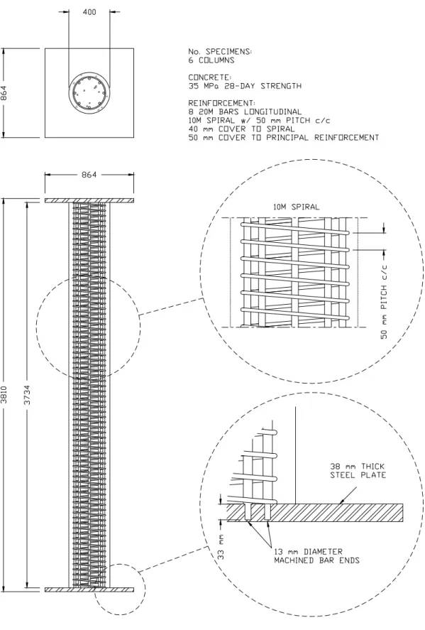
The experimental program consisted of fire tests on two circular columns, both of which were strengthened with the MBrace® CF130 FRP externally-bonded strengthened system1. The columns were designated as Column 3 and Column 4 (Previous tests conducted as part of this ongoing study were designated as Columns 1 and 2 [4]). Details of the reinforced concrete columns are shown in Figure 1.
1
Certain commercial products are identified in this report in order to adequately specify the experimental procedure. In no case does such identification imply recommendations or endorsement by the National Research Council, nor
Dimensions
Both columns were identical, with a 400 mm diameter and a 3810 mm length from end plate to end plate. The cross-sectional dimensions and reinforcement details of the columns are given in Figure 1.
Materials
Cement
Type 10 Portland cement, a general purpose cement for construction of reinforced concrete structures, was used for constructing the reinforced concrete columns.
Aggregates
Both columns were fabricated with siliceous aggregate concrete. When concrete is made with coarse aggregate consisting mainly of quartz and silica (for example granite), it is referred to as siliceous aggregate concrete. Structural members consisting of concrete manufactured from siliceous aggregates tend to have slightly lower fire resistances than those fabricated using carbonate aggregates (e.g. limestone) [5]. The fine aggregate used was natural sand. The maximum aggregate size used in the columns was 14 mm.
Reinforcement
Deformed bars meeting the requirement of CSA G30.18 [6] were used for main longitudinal bars, spirals and ties. All reinforcement had a specified yield strength of 400 MPa. The longitudinal reinforcement was comprised of eight 19.5 mm diameter bars, symmetrically placed, with 40 mm clear cover to the spiral reinforcement. The main reinforcing bars were welded to steel end plates. The resulting percentage of longitudinal steel was 1.91%. The details of the longitudinal reinforcing bars are given in Figure 1 and Table 2.
The lateral reinforcement for the columns consisted of 10 mm diameter deformed steel spiral with a centre-to-centre pitch of 50 mm. The location and layout of the transverse steel reinforcement are also given in Figure 1.
Concrete Mix
A single batch of concrete was used for fabricating the columns. The concrete was supplied by Lafarge Ready-Mix, Kingston, Canada, and was delivered to the Structures Testing Laboratory at Queen’s University. The concrete for the columns was designed to have a 28-day compressive strength of 35 MPa.
The batch quantities and specified properties of the concrete mix proportions are provided in Table 1. The average 28-day cylinder compressive strength was 32.7 MPa and the corresponding compressive strength on the day of the fire test was 32.9 MPa. In both cases, the compressive strength is based on the average result of three standard cylinder tests.
Fabrication
The columns were fabricated and cured in the Structures Testing Laboratory at Queen’s University in Kingston, ON and then shipped to NRC for full-scale fire testing. The columns
were cast vertically using Sonotube™ formwork. Chromel-alumel thermocouples were secured to the reinforcing steel at specific locations before the cage was precisely positioned in the form. To avoid any possible dislocation of the thermocouples in the columns during casting, a careful working plan was followed, as described below.
Reinforcing Bars and Steel Plates
All columns were 3810 mm in length, measured from end plate to end plate. The longitudinal reinforcing bars were cut to 3790 mm and machined at both ends to the diameters shown in Figure 1.
The details of the steel end plates, including dimensions, are shown in Figure 1. Holes, with a diameter 1.6 mm greater than that of the machined ends, were drilled through the plates to accommodate the longitudinal bars. The main reinforcing bars and lateral ties were tied together to complete the steel cage. The cage was then placed against one end plate in such a way that the machined segments of the bars were positioned in the holes.
Welding
All longitudinal reinforcing bars were welded to the top and bottom end plates. The provisions of W186-M1990 [7] were followed when welding the plates and bars. Special attention was given to the centering and squaring of the end plates during welding. Mild steel welding rods were used to fill the holes, which had been drilled to accommodate the reinforcing bars, on the outer face of the plates. The rough surface of the welded joints on the drilled outer face of the plates was ground to a smooth finish.
The welding of the bottom steel plate was performed before casting the columns. The top plate was placed after pouring and curing of the concrete. Before positioning the top plate, a layer of mortar was spread over the top surface of the column to ensure good contact between the steel plate and the concrete. Using a similar procedure as for the bottom plate, the top plate was welded to the longitudinal bars and the outside face was smoothed using a grinder.
Instrumentation
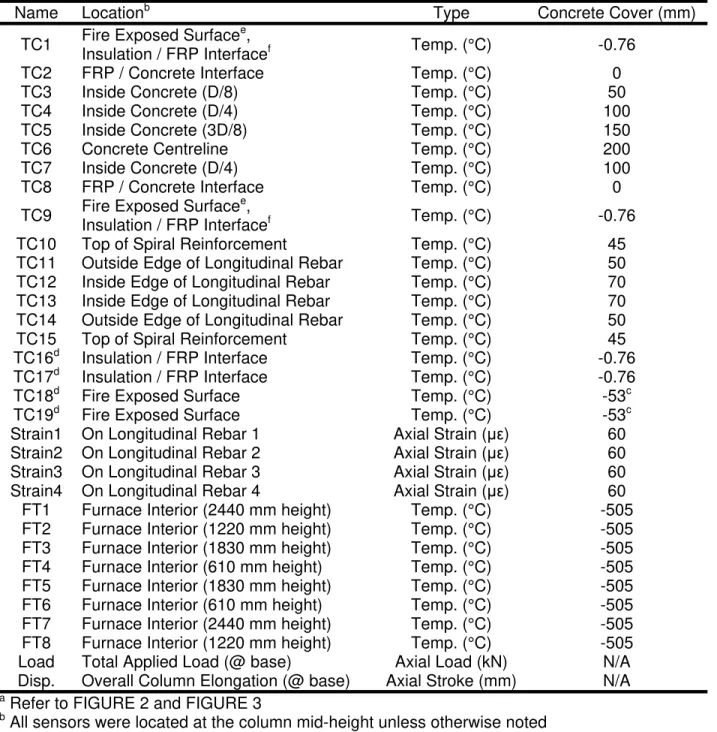
Both columns were instrumented with thermocouples and electrical resistance strain gauges at the column mid-height. Figures 2 and 3 show the location and number of various sensors in the columns, with some differences noted for Column 3 since it was not protected with supplemental fire insulation. Table 3 gives a summary of all instrumentation used during the column tests.
Thermal instrumentation consisted of chromel-alumel (Type-K) thermocouples. Thermocouple frames were fabricated for the thermocouples in the concrete (thermocouples 4 to 7) by fastening individual thermocouples to 3.1 mm diameter steel drill-rod and securely fastening the drill rod to the steel reinforcement cage with wire ties prior to pouring the concrete. Thermocouples 10 to 15 were attached directly to the reinforcing cage using wire ties. Thermocouple wires for sensors placed inside the columns were threaded up the sides of the vertical reinforcing bars inside the reinforcing cage and exited the side of the columns just below the top end plate.
For thermocouples 2 and 8, at the FRP/concrete interface, shallow vertical grooves were ground into the side of the columns after pouring the concrete from the top-plate to the column mid-height using a hand grinder. The wires for thermocouples 2 and 8 were placed inside the grooves and run down the sides of the columns to the appropriate locations. The grooves were filled with an epoxy patching compound. Thermocouples 1, 9, 16 and 17 were attached to the exterior of the FRP wrap using 5-minute epoxy. Thermocouples 18 and 19 were attached to the columns’ surface with epoxy before commencing the spray application of the insulation (described below).
The number and location of strain gauges in the circular columns is depicted in Figures 2 and 3. Strain gauges were installed inside the column at its mid-height in an attempt to gain insight into the effectiveness (or lack thereof) of the FRP wrap and to detect any bending in the column during the tests. High temperature strain coupons were fabricated and installed on the longitudinal reinforcing steel at 4 locations, distributed evenly around the column cross-section at mid-height. The strain coupons were fabricated by installing KyowaTM KFU-5-120-C1-11 high-temperature foil gauges on 150 mm long coupons of 3 mm by 13 mm cold-flat-finished mild steel plate. The gauge lead-wires were soldered to high-temperature polyamide terminal pads using high-temperature silver solder, and high-temperature KyowaTM Type L-4 strain gauge wire was soldered to the terminal pads. The strain gauge wires were sheathed with protective PVC tubing, which served to provide mechanical protection for the wires while the columns were cast, as well as waterproofing protection inside the hardened concrete. A surface protection and waterproofing layer was applied to the gauge/lead-wire/terminal pad assembly using SuperflexTM Red High Temp RTV Silicone Adhesive Sealant. Once fabricated, the metal coupons were tack-welded to the vertical reinforcing bars, and the lead wires ran up the sides of the vertical reinforcing bars and exited the forms just below the top end-plate.
Forms
The formwork consisted of 400 mm inside diameter SonotubeTM formwork. The formwork was tied to the column base plate using metal brackets and tap screws to ensure accurate location of the formwork within the column. An aluminum collar was used at the top of the column to keep the formwork in place.
Concrete Placement
The columns were poured vertically in a single lift, with concrete supplied by a local ready-mix plant. The concrete was placed using a large hopper attached to an overhead crane, and a series of rubber chutes of various lengths (fabricated specifically for this project to ensure that the concrete never free-fell more than 0.6 m while being placed, and so that the concrete placing operations could be conducted without damaging the instrumentation at the column mid-height). The concrete was hand-vibrated during each lift with a 3.65 m long, 32 mm diameter wand vibrator to ensure adequate consolidation.
Curing
Once cast, the columns were cured in a humidified plastic enclosure at 21°C to 24°C and 100% relative humidity for seven days, at which point the formwork was removed. The columns were allowed to cure in the laboratory, at ambient temperature and relative humidity, for at least one year until they were ready for wrapping and testing.
FRP Strengthening
The FRP strengthening system for the columns consisted of two layers of the MBrace® CF130 unidirectional carbon/epoxy FRP system with an MBrace® epoxy saturant/adhesive. Details of the strengthening system are provided in Table 4. The strengthening system was installed at the National Research Council of Canada by the installation specialists from Degussa Building Systems and graduate students from Queen’s University. The strengthening system theoretically increased the axial load capacity of the columns by 64% based on ACI 440 guidelines [8], 9% based on CSA-S806 guidelines [9], 32% based on ISIS Canada guidelines [10] and 42% based on ICC/ICBO AC-125 guidelines [10]. Details of the load calculations are provided in Appendix A.
The circumferential sheets were installed on the columns’ surface in accordance with Degussa Building Systems installation procedures. The FRP application process on the columns was as follows:
1. The concrete substrate was checked for any defects or protrusions that could affect the ability of the FRP to bond to the concrete. No defects were found on the specimens.
2. Since the column specimens were cast in a high quality formwork, the surface of the columns was extremely smooth. The concrete substrate was prepared by sandblasting, to achieve a minimum surface texture prescribed by the International Concrete Repair Institute (ICRI) [11]. The surface was lightly brushed using a heavy-duty scrub brush to remove any dust or loose debris after the mechanical abrasion.
3. MBrace® primer was applied to the concrete surface using a small nap roller.
4. MBrace® putty was applied to the primed surface with a trowel to fill any surface defects. 5. MBrace® saturant was applied to the primed and puttied surface with a medium nap roller to
a thickness of approximately 0.5 mm.
6. Resin-saturated FRP sheets were placed around the concrete surface of the columns and gently pressed into the saturant. The sheets were wrapped around the columns in 610 mm wide lifts, starting at the bottom and working to the top of the column.
7. A roller was used to roll in the direction of the fibres to facilitate impregnation and remove any air bubbles.
8. A second coat of saturant was applied with a medium nap roller.
9. Immediately after the second coat of saturant was applied, the second layer of FRP was placed on the columns’ surface as described in steps 6 and 7.
10. The FRP was allowed to cure for at least 12 hours at ambient temperature (approximately 15°C).
Fire Protection
A unique insulation scheme was developed by Degussa Building Systems to provide supplemental fire insulation to one of the wrapped columns (Column 4). The other column (Column 3) was tested without insulation (i.e. the FRP wrap was fully exposed to the fire). The insulation system, currently denoted as MBrace® Insulation System 1, is a spray-applied cementitious mortar with calcareous lightweight filler and various other unique additives and was originally developed for fire-resistant tunnel linings in Europe. This system is essentially thermally inert up to temperatures in excess of 1000°C and has a very low thermal conductivity. When exposed to flames, the insulation releases chemically combined water in the form of water vapour, which helps to maintain the plaster’s temperature below 100°C until all of the water has been driven off as steam. Meanwhile, the insulating and decomposition action of
overall fire-proofing characteristics. The insulation also prevents explosive spalling when concrete is exposed to a high heating rate. Details of the insulation systems are provided in Figure 4. Column 4 was designed to have a nominal insulation thickness of 38 mm; however, after the installation of the insulating material, the average thickness of the insulation was 53 mm.
The insulation was installed on the column in accordance with Degussa Building Systems installation procedures. Figure 4 provides details of the insulation layout for the column. The application process for the column was as follows:
1. A thin layer of MBrace® Primer was applied to the cured FRP surface using a roller, and was allowed to become tacky.
2. Once the MBrace® Primer coat was tacky, MBrace® Insulation System 1 was spray-applied on the surface of the column, using an industrial-scale shotcreting rig, until the column was fire-protected with the desired thickness.
3. After the spray-application of the insulation system, the FRP-strengthened column did not have a uniform desired thickness around it. Regardless, the MBrace® Insulation System 1 was allowed to cure in the Fire Testing Laboratory at the National Research Council of Canada (NRC).
4. Once the insulation cured, the MBrace® Insulation System 1 was applied by hand using a trowel to achieve a uniform insulation thickness. The surface of the cured insulation was moistened prior to the hand-application of the insulation.
5. The MBrace® Insulation System 1 was again allowed to cure in the Fire Testing Laboratory at the National Research Council of Canada (NRC) until the date of the fire test (about 10 months waiting period before the test).
Test Apparatus
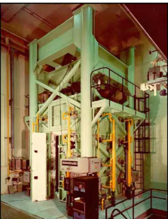
The fire endurance experiments were carried out by exposing the columns to heat in a furnace specially built for fire testing loaded columns. The test furnace was designed to produce conditions to which a member might be exposed during a fire, i.e., temperatures, structural loads and heat transfer, and to meet the requirements of ASTM E119 [12] or CAN/ULC S101 [13]. It consists of a steel framework supported by four steel columns, with the furnace chamber inside the framework (Figure 5). There are small view ports along the wall of the furnace framework that allow viewing of the exposed side of the specimens during the fire testing. The characteristics and instrumentation of the furnace are described in detail by Lie [5]. Only a brief description of the furnace and the main components are given here.
Loading Device
Although the column furnace is capable of producing both axial and lateral force, the columns were subjected to only sustained axial load from above using a loading system with a hydraulic jack that has a load capacity of 9778 kN. The jack is located at the bottom of the furnace chamber. The plates on the top of the jack can be used as a platform to which the column can be mounted.
Furnace Chamber
The furnace chamber has a floor area of 2642 x 2642 mm and is 3048 mm high. The interior of the chamber is lined with ceramic insulating materials that efficiently transfer heat to
the specimen. The ceiling and floor insulation protect the column end plates from fire. It should be noted that only 3200 mm of the column is exposed to fire.
Heat is supplied by 32 propane gas burners in the furnace chamber, arranged in eight columns containing four burners each. The total capacity of the burners is 4700 kW. Each burner can be adjusted individually, which allows for a high degree of temperature uniformity in the furnace chamber. The pressure in the furnace chamber is also adjustable and was set somewhat lower than atmospheric pressure.
Furnace Instrumentation
The furnace temperatures were measured with the aid of eight Type K chromel-alumel thermocouples. The thermocouple junctions were located 305 mm away from the surface of the test specimen, at various heights. Two thermocouples were placed opposite each other at intervals of 610 mm along the height of the furnace chamber. The locations of their junctions and their numbering are shown in Figure 6. Thermocouples 4 and 6 were located at a height of 610 mm from the floor, Thermocouples 2 and 8 at 1220 mm, Thermocouples 3 and 5 at 1830 mm and Thermocouples 1 and 7 at 2440 mm. The temperatures measured by the thermocouples were averaged automatically and the average temperature was used to control the furnace temperature.
The load was controlled by servocontrollers and measured with pressure transducers. The accuracy of controlling and measuring loads is about 4 kN at lower load levels and relatively better at higher loads.
The axial deformation of the test columns was determined by measuring the displacement of the jack that supported each column. The displacements were measured using transducers with an accuracy of 0.002 mm.
TEST CONDITIONS AND PROCEDURES
The columns were installed in the furnace by bolting their end plates to the test frame loading head at the top and the hydraulic jack at the bottom. This resulted in a fixed-fixed end condition for both members, which most accurately simulates the end conditions to be expected in an actual building.
Before testing, the moisture condition at the centre of the columns was measured by inserting a VaisalaTM moisture sensor into a hole drilled in the concrete. The relative humidity of each column is given in Table 5. These values were used to estimate the moisture content of the concrete using the procedures outlined in ASTM E119 [12].
End Conditions
Both columns were tested with both ends fixed, i.e., restrained against rotation and horizontal translation. For this purpose, eight 19 mm (3/4 in.) diameter bolts, spaced regularly around the column, were used at each end to bolt the end plate to the loading head at the top and to the hydraulic jack at the bottom.
Loading
Both columns were tested under a concentric axial compressive load. The applied load on the circular columns was 2635 kN, which represents 56% of the ultimate strengthened design capacity according to ACI 440.2R-02 [8], 99% according to CSA S806-02 [9], 82% according to ISIS Design Manual No. 4 [10] and 64% according to ICBO AC-125 [14]. The factored compressive resistances of each column, along with the applied loads, are given in Table 5. Full details of the load calculations for the columns are given in Appendix A.
In both tests, loads were applied to the columns starting approximately 45 minutes before the start of the fire endurance tests. Loads were maintained until a condition was reached at which no further increase of the axial deformations could be measured. This condition was selected as the initial condition of the column deformation during the fire test. The load was maintained at a constant value throughout the fire endurance tests.
Column 3 failed under its sustained service load during the test, however, after 5 hours of fire exposure, Column 4 had demonstrated no signs of impending failure, and so the loads were increased until failure was observed. The failure loads for both columns are given in Table 5.
Fire Exposure
The ambient temperature at the start of each test was approximately 20°C. During the fire tests, each column was exposed to heating controlled in such a way that the average temperature in the furnace followed, as closely as possible, the ULC S101 [13] standard time-temperature curve, which is equivalent to the ASTM E119 [12] standard fire curve. This curve can be approximately expressed using the following equation:
(
e
)
t
T
f=
20
+
750
1
−
−3.79533t+
170
.
41
where: t = time in hoursTf = temperature of furnace in °C Recording of Results
The furnace, concrete, steel, insulation and FRP temperatures (where applicable), as well as load, axial deformations of the columns, and strains in the longitudinal reinforcing steel, were recorded at one-minute intervals throughout the fire tests. The fire behaviour of the insulation and FRP wrap, crack propagation and the occurrence of spalling in columns were also monitored during the tests through small observation windows in the column furnace walls. Post-test observations were made of the failure mode, extent and nature of spalling, and condition of rebars and ties where possible. It should be noted that the insulation on Column 4 remained intact for the whole duration of the fire tests. Based on design calculations, the column was expected to fail by crushing; also, there was no buckling observed following the fire test of Column 4.
Failure Criterion
The columns were considered to have failed, and the tests stopped, if the hydraulic jack, which has a maximum speed of 76 mm/minute, could no longer maintain the sustained load. If
this failure criterion was not reached during the first 5 hours of the test, the load was increased until the column failed, at which point the test was stopped.
RESULTS AND DISCUSSION
The results of the column tests are summarized in Table 5, in which the column characteristics, test conditions, fire endurances, and failure modes are given for each column. The furnace, concrete, steel, insulation, and FRP temperatures recorded during the tests, as well as the axial deformations of the column specimens, are presented graphically in Figures B1, B2 and B3 in Appendix B, where positive axial deformation values indicate expansion of the column. Some typical photos of the FRP-wrapped and insulated columns before and after fire testing are shown in Figures 10 and 11.
General Observations
Column 3 resisted the sustained load of 2635 kN for 3.5 hours, at which point it failed in a sudden manner by a combined spalling of the concrete cover and apparent crushing of the concrete core. However, after 5 hours of fire exposure, Column 4 had not failed under a sustained load of 2635 kN, so the load level was increased to 4575 kN, at which point the column failed in a non-violent fashion, with the insulation remaining largely intact.
Performance of Insulation
Providing excessive amounts of insulation around the reinforced concrete column may not be beneficial as the insulating material would be bonded to the FRP surface with a tack coat of primer and without any mechanical anchorage. Based on previous studies [4, 15 and 16], it was determined that 25 mm thick insulation would protect the reinforced concrete elements and the FRP-strengthening systems for a reasonable amount of time. To ensure a successful fire test, where Column 4 achieves a desirable fire endurance rating, it was decided to provide 38 mm thick insulation. Since an accelerant was used for rapid curing of the insulation system and the application of the insulation was performed in several lifts, it was difficult to have a uniform insulation thickness of 38 mm. After successfully installing the insulation system, the average thickness of the insulation on Column 4 was determined to be 53 mm. As mentioned previously, uninsulated Column 3 was exposed to fire for 3.5 hours before it reached failure, and insulated Column 4 endured the exposure to fire for more than 5 hours under the sustained axial load. This indicates that the provision of 53 mm of Mbrace® Insulation System 1 provided a minimum additional 1.5 hours of fire endurance to the column. Also, the insulation system remained intact with minor cracks on Column 4 for the duration of the fire test.
Column 3
Column 3 was not provided with any supplemental fire insulation, and the FRP strengthening system was thus fully exposed to the fire. As expected, the FRP wrap ignited within minutes of fire exposure, at which point much of the epoxy saturant/adhesive burned off, leaving only a residual char which continued to weakly adhere the carbon fibres to the surface of the column. It is assumed that the FRP wrap lost virtually all of its structural effectiveness after the epoxy had burned off, although tests on the specific wrap materials at high temperature will be required to confirm this conservative assumption. Once the epoxy had burned off, the appearance of the column remained essentially unchanged for the duration of the test. The overall timeline and observations recorded during the fire test are given below.
Time hr:min
Observations
0:00 Column loaded to 2635 kN; fire initiated
0:05 Flames observed on the surface of the FRP-wrap; epoxy saturant/adhesive burning
0:24 Fibres of the FRP wrap were visible and were observed to be glowing
0:33 Concrete substrate visible from mid-height to the bottom of the column; FRP wrap completely gone
0:53 FRP-wrap completely debonded from the concrete surface over full height 1:48 Minor vertical cracks (< 1 mm wide) visible on the concrete surface
2:24 Small widening of vertical cracks observed 3:30 Structural failure of column; fire test halted Post failure of Column 3:
Due to the sudden and explosive failure mode observed for the column major spalling of the concrete cover occurred at failure and some of the longitudinal and spiral steel was exposed (refer to Figure 10). However, no obvious buckling of rebars or deformation of the spiral reinforcement occurred in the column.
Column 4
The MBrace® insulation performed extremely well under fire exposure, and remained intact until the end of the tests (even beyond failure). The only change observed in the appearance of the insulation during fire exposure was the formation of cracks, generally less than 5 mm wide, which gradually appeared and widened as the test progressed. Further tests will be required to determine installation procedures and insulation thicknesses that will minimize and/or prevent cracking. The overall timeline and observations recorded during the fire test are given below.
Time hr:min
Observations
0:00 Column loaded to 2635 kN; fire initiated
1:23 Flames observed from the visible cracks on the surface of the insulation 1:45 Flames became more vigorous as the cracks widened
5:00 Initiated increase in load from 2635 kN to 4575 kN 5:27 Structural failure of column; fire test halted
Post failure of Column 4:
The failure mode observed for the column was non-violent, and the insulation system appeared to remain largely intact even after failure (refer to Figure 11).
Fire Performance
Figures B1 and B2 of Appendix B provide a comparison of recorded temperatures at various locations in Columns 3 and 4 during exposure to fire. The data demonstrate that it is possible to maintain the temperature of the FRP wrap below the glass transition temperature of the FRP material, which was 71 °C, for up to 0.5 hours by providing the requisite thicknesses of MBrace® Insulation System 1. Furthermore, based on the temperatures recorded in the concrete and reinforcing steel during fire testing, since temperatures of less than 200ºC are not
structurally significant in terms of deterioration of mechanical properties for either concrete or steel, it can be stated with confidence that Column 4 maintained its full unconfined axial load carrying capacity for greater than 5 hours of exposure to the ULC S101 or ASTM E119 standard fires.
Load Capacity and Fire Endurance
The fire endurance of a column is defined as the time to reach failure under exposure to the standard fire [12]. For columns, failure is defined in terms of load-carrying capacity. Thus, the fire endurance of an FRP-wrapped column is defined as the point in time during fire exposure when the load capacity of the member falls below the nominal load to be expected on the member during service [17].
The room temperature axial load capacities of Columns 3 and 4 were assumed to be the same, since the insulation was assumed to have negligible strength and were thus not likely to significantly increase the axial load capacity of Column 4. The nominal room temperature strength of both columns was calculated to be 4719 kN based on the ISIS Canada [10] design guidelines without resistance factors (or 6564 kN using the ACI 440 Guidelines [8]). Examination of the temperature data (refer to Figure 8) obtained during the fire endurance test of Column 4 leads to the conclusion that the wrap had likely been rendered ineffective even in the insulated column due to increased temperatures in excess of its glass transition temperature (Tg), which is about 71 °C for the MBrace® FRP system used in the current study, but that the
concrete and reinforcing steel should have retained virtually all of their room-temperature strength. When the load was gradually increased after 5 hours of exposure, Column 4 was expected to fail around the nominal load capacity for an equivalent unwrapped column at room temperature but, it failed above the nominal load capacity. The nominal (unfactored) compressive strength of an equivalent unwrapped column was calculated to be 3671 kN using the CSA A23.3-94 [18] code or 3842 kN using ACI 318-95 [19] and Column 4 failed around 4575 kN. The additional strength of Column 4 may be due to the confinement effects of the spiral steel reinforcement, which was not accounted for in the calculation of the nominal (unfactored) strength of the unwrapped column (refer to Appendix-A), and also, the concrete may have achieved a higher stress during the fire test than the stress value (which was approximately 0.85 times the specified 28-day compressive strength) used in the calculation of the nominal strength.
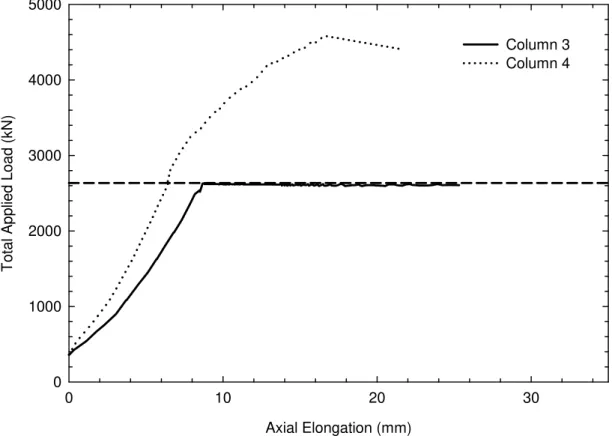
Examination of Figure 7, which shows load-deflection data for both columns (including the preload and fire test phases), shows that Columns 3 and 4 had failure loads of approximately 2606 kN and 4403 kN, respectively. Figure 9 demonstrates a graphical representation of the load capacities of the two columns with respect to their design and predicted values, and also their failure load during the fire tests. Even though the FRP strengthening system was probably lost by the end of the fire test of Columns 3 and 4, the loss of strength of the two columns was different during the fire tests. In the case of Column 3, the tested strength of the column was lower than the unfactored predicted room temperature strength of an unwrapped column, calculated according to either the Canadian or American concrete design guidelines, which indicates that without supplementary fire protection, Column 3 had experienced significant loss of strength during the fire exposure. However, even after 5 hours of exposure to the ASTM E119 [11] standard fire, Column 4 failed at loads considerably larger than the unfactored predicted room temperature strength of an unwrapped column, again based on either Canadian and American concrete design guidelines, which shows that the column had retained most of its unstrengthened room temperature strength during the fire
exposure. This was because the internal temperatures of Column 4 were maintained at low temperature by the supplementary fire protection.
In terms of the fire endurance of the tested columns, it can be stated with confidence that, for the insulated column for the full 5.5 hour duration of the test, the column was able to carry its FRP-confined (strengthened) service load of 3172 kN according to ACI 440 guidelines [8]. This would result in a 5-hour ASTM E119 [12] or ULC S101 [13] fire endurance rating with design loads calculated in accordance with the ACI 440 guidelines [8]. It is interesting to note also that the unfactored FRP-confined service load calculated according to the ISIS design guidelines [10] is 2171 kN for the columns tested herein, which is less than the observed failure load for either columns after exposure to the standard fire. Failure loads of Columns 3 and 4 are 2635 kN and 4575 kN, respectively. Column 3 failed under its sustained axial service load at about 3.5 hours of exposure to the ASTM E119 [12] standard fire. Therefore, Column 3 achieved a 3-hour fire endurance rating under load.
Column Comparison
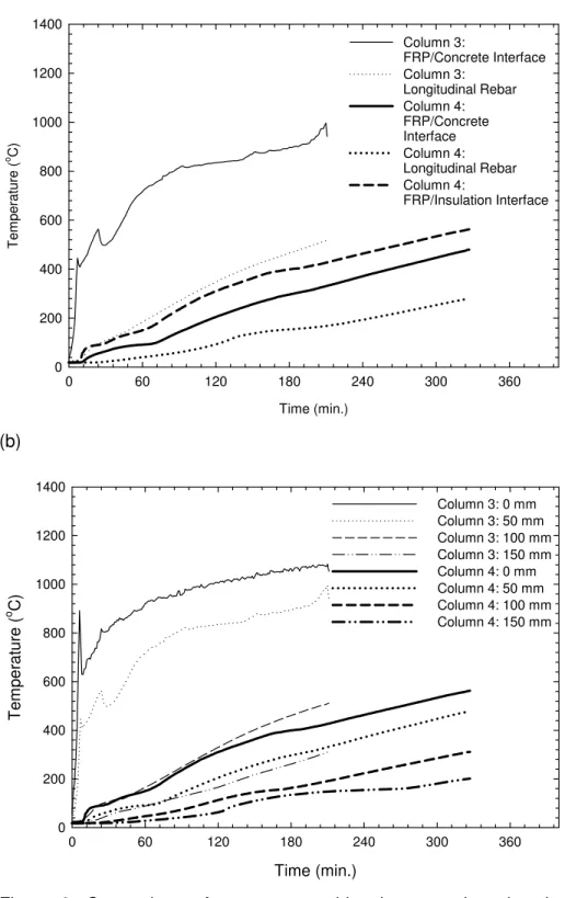
Figure 8 provides a comparison of recorded temperatures at various locations in Columns 3 and 4. Shown in the figure are average temperature histories at the insulation/FRP interface, the FRP/concrete interface, the outside-rebar location, and the column centreline. It is evident that the insulation has a significant effect on the temperatures observed in the columns. Further work is required to determine the precise thicknesses of insulation required to achieve specific levels of fire endurance. This work is ongoing through additional fire tests and the development and use of validated numerical heat transfer models to simulate the behaviour of insulated FRP-wrapped columns under exposure to a standard fire.
SUMMARY
Based on the results of full-scale fire endurance tests on two circular FRP-wrapped (confined) reinforced concrete columns, the following points can be summarized:
1. FRP materials used as externally-bonded reinforcement for concrete structures are sensitive to the effects of elevated temperatures. FRPs experience degradation in strength, stiffness, and bond at temperatures exceeding the glass transition temperature, Tg, of the polymer
matrix.
2. By providing proper fire insulation, as described in this report, a 5 hour fire endurance rating can be achieved for loaded circular reinforced concrete columns strengthened with FRP wraps.
3. The insulation systems described herein are effective fire protection systems. Visual observations made during the fire tests indicated that the insulation remained intact for more than 5 hours of exposure to the ULC S101 [13] standard fire.
4. The supplemental fire protection was not able to maintain the temperature of the FRP below its glass transition temperature for the duration of the fire endurance test. The temperature of the FRP was below its glass transition temperature for only about 34 minutes, even for the well-insulated column.
5. The supplemental fire protection system was able to maintain low temperatures in the concrete and primary steel reinforcement during fire, thus enabling the concrete and steel to retain their room temperature strength during the fire endurance tests.
REFERENCES
1. NRC 1995. National Building Code of Canada 1995. National Research Council of Canada, Ottawa.
2. Kodur, V.K.R. 1999. Fire Resistance Requirements for FRP Structural Members. Proceedings of the Annual Conference of the Canadian Society for Civil Engineering, Regina, Saskatchewan, pp. 83-95.
3. Bisby, L.A., Green, M.F., and Kodur, V.K.R. 2001. Fire Behaviour of FRP-Wrapped Reinforced Concrete Columns. In Forde, M.E. (Ed.), Structural Faults and Repair – 2001, London, England, July 4th-6th, CD-ROM.
4. Bisby, L.A. 2003. "Fire Behaviour of FRP Reinforced or Confined Concrete," Doctoral
Thesis, Department of Civil Engineering, Queen's University, Kingston, Ontario, Canada.
372 pp.
5. Lie, T.T. 1980. New Facility to Determine Fire Resistance of Columns, Canadian Journal of Civil Engineering, 7(3), pp. 551-558.
6. CSA 2002. G30.18: Billet-Steel Bars for Concrete Reinforcement. Canadian Standards Association.
7. CSA 2002. W186-M1990: Welding of Reinforcing Bars in Reinforced Concrete Structures. Canadian Standards Association.
8. ACI 2002. ACI 440.2R-02: Guide for the design and construction of externally bonded FRP systems for strengthening concrete structures. American Concrete Institute, Farmingtion Hills, MI.
9. CSA 2002. S806: Design and construction of building components with fibre-reinforced polymers. Canadian Standards Association.
10. ISIS 2001. Strengthening reinforced concrete structures with externally bonded fibre reinforced polymers. Intelligent Sensing for Innovative Structures Canada, Winnipeg, Manitoba.
11. ACI 2003. Concrete Repair Manual. American Concrete Institute, Farmington Hills, MI. 12. ASTM 2001. Test Method E119-01: Standard Methods of Fire Test of Building Construction
and Materials. American Society for Testing and Materials, West Conshohocken, PA.
13. ULC 1989. Standard Methods of Fire Endurance Tests of Building Construction and Materials. CAN/ULC-S101-M89, Underwriters’ Laboratories of Canada, Scarborough, ON. 14. ICC (2003). Interim Criteria for Concrete and Reinforced and Unreinforced masonry
strengthening using Fiber-Reinforced Polymer (FRP) Composite Systems – AC125, International Code Council (ICC) Evaluation Services, Inc., U.S.A.
15. Williams, B.K. 2004. Fire Performance of FRP-Strengthened Reinforced Concrete Flexural Members. Phd thesis, Department of Civil Engineering, Queen’s University, Kingston, Ontario.
16. Chowdhury, E. U. 2005. Performance in fire of reinforced concrete T-beams strengthened with externally bonded fibre-reinforced polymer sheets. M.Sc. thesis, Department of Civil Engineering, Queen's University, Kingston, Ontario.
17. Lie, T.T. 1992. Structural Fire Protection. American Society of Civil Engineers Manuals and Reports on Engineering Practice No. 78. ASCE, New York, NY.
18. CSA, 1994. CAN/CSA A23.3-94: Design of Concrete Structures. Canadian Standards Association, Ottawa, Ontario.
19. ACI 1995. Building Code Requirements for Structural Concrete (ACI 318-95). American Concrete Institute, Farmington Hills, MI.
Table 1: Batch quantities and measured properties of concrete for the columns
Mix Parameter Columns
Aggregate Type Crushed Granite (Siliceous)
Maximum Aggregate Size 14
Type 1 Cement (kg/m3) 280
Coarse Aggregate (kg/m3) 1020
Fine Aggregate (kg/m3) 980
Water (kg/m3) 152
Mid-range Water Reducer As per MBT* specs
Slump (mm) Max 150
Water-cement Ratio 0.54
Specified 28-day Strength 32.7
Test day Strength 32.9
Table 2: Specimen dimensions and steel reinforcement details Column No. Dimensions Height (mm) Primary Reinforcement Hoop Reinforcement Yield Strength (MPa) 3 400 mm Ø 3810 8 – 20M bars 10M spiral – 50 mm pitch 456 MPa 4 400 mm Ø 3810 8 – 20M bars 10M spiral – 50 mm pitch 456 MPa
Table 3: Instrumentation for the circular column testsa
Name Locationb Type Concrete Cover (mm)
TC1 Fire Exposed Surface e
,
Insulation / FRP Interfacef Temp. (°C) -0.76
TC2 FRP / Concrete Interface Temp. (°C) 0
TC3 Inside Concrete (D/8) Temp. (°C) 50
TC4 Inside Concrete (D/4) Temp. (°C) 100
TC5 Inside Concrete (3D/8) Temp. (°C) 150
TC6 Concrete Centreline Temp. (°C) 200
TC7 Inside Concrete (D/4) Temp. (°C) 100
TC8 FRP / Concrete Interface Temp. (°C) 0
TC9 Fire Exposed Surface e
,
Insulation / FRP Interfacef Temp. (°C) -0.76
TC10 Top of Spiral Reinforcement Temp. (°C) 45
TC11 Outside Edge of Longitudinal Rebar Temp. (°C) 50
TC12 Inside Edge of Longitudinal Rebar Temp. (°C) 70
TC13 Inside Edge of Longitudinal Rebar Temp. (°C) 70
TC14 Outside Edge of Longitudinal Rebar Temp. (°C) 50
TC15 Top of Spiral Reinforcement Temp. (°C) 45
TC16d Insulation / FRP Interface Temp. (°C) -0.76
TC17d Insulation / FRP Interface Temp. (°C) -0.76
TC18d Fire Exposed Surface Temp. (°C) -53c
TC19d Fire Exposed Surface Temp. (°C) -53c
Strain1 On Longitudinal Rebar 1 Axial Strain (με) 60
Strain2 On Longitudinal Rebar 2 Axial Strain (με) 60
Strain3 On Longitudinal Rebar 3 Axial Strain (με) 60
Strain4 On Longitudinal Rebar 4 Axial Strain (με) 60
FT1 Furnace Interior (2440 mm height) Temp. (°C) -505
FT2 Furnace Interior (1220 mm height) Temp. (°C) -505
FT3 Furnace Interior (1830 mm height) Temp. (°C) -505
FT4 Furnace Interior (610 mm height) Temp. (°C) -505
FT5 Furnace Interior (1830 mm height) Temp. (°C) -505
FT6 Furnace Interior (610 mm height) Temp. (°C) -505
FT7 Furnace Interior (2440 mm height) Temp. (°C) -505
FT8 Furnace Interior (1220 mm height) Temp. (°C) -505
Load Total Applied Load (@ base) Axial Load (kN) N/A
Disp. Overall Column Elongation (@ base) Axial Stroke (mm) N/A
a
Refer to FIGURE 2 and FIGURE 3 b
All sensors were located at the column mid-height unless otherwise noted c
Cover to TCs 18 and 19 represents the average thickness of the insulation d
Thermocouples instrumented only on Column 4 e
Column 3 f
Table 4: FRP wrap and insulation details used in the experimental program Column No. FRP Wrap No. of Layers Insulation Fire Test Load Ratio 3 CF 130 2 None 0.81 4 CF 130 2 53mm MBrace
Insulation System No. 1
0.81
Table 5: Summary of results of fire endurance tests on Column 3 and Column 4 Column No. Relative Humidity (%) Moisture Contenta (% vol.) Design Load Capacityb (kN) Applied Loadc (kN) Failure Load (kN) Fire Endurance (min.) Failure Mode 3 86.1 7.0 3225 2635 2635 210 Crushing/Spalling 4 86.1 7.0 3225 2635 4575 >300 Crushing a
Determined in accordance with ULC S101 [12] b
Determined in accordance with ISIS Canada Design Guidelines [9]. Refer to Appendix A. c
The applied load represents the full unfactored service load, assuming a live-to-dead load ratio of 1:1
4 5 6 1 7 8 9 3 2 4 1 3 2 5 6 7 8 9 10 11 12 13 15 14 SG1 SG2 SG3 SG4 SG4 SG1 SG2 SG3 11 10 12 13 14 15 FRP SG - Strain Gauge D 5 TCs @ D/8 D/4 D/4 Thermocouples (a) (b) (c)
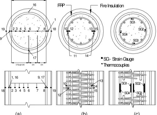
Figure 2: Location & numbering of thermocouples and strain gauges in Column 3 at mid-height (a) Thermocouples in the concrete and on FRP
(b) Thermocouples on the reinforcing steel (c) Strain gauges on the reinforcing steel
SG1 SG2 SG3 SG4 SG4 SG1 SG2 SG3 11 10 12 13 14 15 18 19 FRP Fire Insulation 16 17 18 19 SG - Strain Gauge D 5 TCs @ D/8 D/4 D/4 Thermocouples 2 4 1, 16 3 2 5 6 7 8 9, 17 10 11 12 13 15 14 4 5 6 9 7 8 1 3 (a) (b) (c)
Figure 3: Location & numbering of thermocouples and strain gauges in Column 4 at mid-height (a) Thermocouples in the concrete and insulation
(b) Thermocouples on the reinforcing steel (c) Strain gauges on the reinforcing steel
MBrace Insulation Prime Coat
MBrace Insulation System No. 1 (See Table 1)
All dimension are in millimiters
50 m m p itc h c /c Concrete Rebar Double ply of MBrace CF130 610 mm (24") wide bands to full height of column. Table 1 Column 3 None MBrace Insulation System No. 1 MBrace Prime Coat MBrace CF130 (See Table 1) 25 mm overlap at all butt splices
* 200 mm overlap at all circumferential splices for MBrace CF130 sheets MBrace CF130 Column 4 Applied in 2 lifts to the maximum thickness possible; approx 53 mm Double ply of MBrace CF130 610 mm (24") wide bands to full height of column.
Figure 4: Details of the FRP-strengthening and fire insulation
Figure 5: Full-Scale Column Furnace in the Testing Facility of the National Research Council, Ottawa (courtesy of NRC)
6 3 4 3048 610 610 610 610 Furnace Chamber 505 1, 2 Furnace Door 2642 7, 8 816 5, 6 505 2642 3, 4 PLAN ELEVATION 1,7 2,8 5
Figure 6: Location of thermocouples in furnace chamber
Axial Elongation (mm) 0 10 20 30 T o ta l A p p lie d Lo ad (k N) 0 1000 2000 3000 4000 5000 Column 3 Column 4
(a) Time (min.) 0 60 120 180 240 300 360 T e m p eratu re ( o C) 0 200 400 600 800 1000 1200 1400 Column 3: FRP/Concrete Interface Column 3: Longitudinal Rebar Column 4: FRP/Concrete Interface Column 4: Longitudinal Rebar Column 4: FRP/Insulation Interface (b) Time (min.) 0 60 120 180 240 300 360 T e m p er atur e ( o C) 0 200 400 600 800 1000 1200 1400 Column 3: 0 mm Column 3: 50 mm Column 3: 100 mm Column 3: 150 mm Column 4: 0 mm Column 4: 50 mm Column 4: 100 mm Column 4: 150 mm
Figure 8: Comparison of temperatures histories at various locations within Column 3 and Column 4 during fire endurance tests
(a) Temperatures at the FRP, insulation and steel reinforcements (b) Temperatures at various locations within concrete
Load Capacity (kN)
0 10 00 20 00 30 00 40 00 50 00 60 00 70 00 ACI 318 Design ACI 318 Predicted CSA A23.3 Design CSA A23.3 Predicted ACI 440 Design ACI 440 Predicted ICBO Design ICBO Predicted ISIS Design ISIS Predicted CSA S806 Design CSA S806 Predicted Applied Load Failure Load of Column 3 Failure Load of Column 4Figure 9: Lo
ad capacit
ie
s of Column 3 and Colu
mn 4 with respect to the
ir design an
d predicted
values
(a) (b)
lumn 3: FRP-wrapped Concrete Column (a) before fire test, and (b) immediately after fire test
(a) (b)
Figure 11: Column 4: FRP-wrapped and Insulated Concrete Column (a) before fire test, and (b) immediately after fire test
APPENDIX-A:
Load Calculations for FRP-Strengthened Reinforced Concrete Columns
This appendix presents detailed load calculations for the reinforced concrete columns that will be tested at the National Research Council, Ottawa, Canada. For unwrapped reinforced concrete columns, loads have been calculated using CSA A23.3-94 [18] and ACI 318/318R-95 [19]. For calculations relating to FRP-wrapped reinforced concrete columns, calculations have been performed in accordance with the ISIS Canada Design Guidelines [10], ACI 440.2R-02 design guide [8], ICBO AC-125 [14] and CSA-S806-02 [9]. Fire endurance test loads were calculated in accordance with ULC-S101 [13], which is equivalent to ASTM E119 [12].
All calculations have been performed in SI units. Design equations from American codes (ACI 318/318R-95 and ACI 440.2R-02) have been performed using Canadian rebar designations and properties. The actual tested properties have been used where available in design calculations for all materials involved. The material properties were as follows:
• Concrete Compressive Strength:
f
c,=
32
.
7
MPa
• Yield Strength of Longitudinal Reinforcing Steel:
f
y=
456
MPa
• Ultimate Tensile Strength of MBrace C130 FRP System:
f
frp,ult=
3800
MPa
• Ultimate Strain of MBrace C130 FRP System:ε
frp,ult=
1
.
67
%
• Elastic Modulus of MBrace C130 FRP System
E
frp=
227
GPa
Axial Load Capacity of the RC ColumnACI 318/318R-95 (Design Strength)
The maximum axial design strength,
φ
P
n(max), for a spirally reinforced concrete column according to ACI 318/318R-95 is taken as (Cl. 10.3.5.1):(
)
[
c g st y st]
n f A A f A
P(max) =0.85
φ
0.85 ' − +φ
[Eqn. A1]Where φ is equal to 0.77 (CL. 9.3.2.2), Ag is the gross cross-sectional area of concrete, and Ast
is the area of longitudinal reinforcing steel in compression. For the columns tested herein this equation becomes:
(
)
[
(
) ( )
(
( )
)
(
)
]
kN
2882
N
10
2882
300
8
456
300
8
200
7
.
32
85
.
0
75
.
0
85
.
0
3 2 (max)=
×
=
⋅
+
−
=
π
φ
P
nACI 318/318R-95 (Predicted Strength)
Omitting member reduction factors in Eqn. A1 for axial load capacity gives the predicted strength of the columns according to ACI 318/318R-95. Thus:
(
)
[
]
(
) ( )
(
( )
)
(
)
[
]
kN
3842
N
10
3842
300
8
456
300
8
200
7
.
32
85
.
0
85
.
0
85
.
0
85
.
0
3 2 ' (max)=
×
=
⋅
+
−
=
+
−
=
π
φ
P
nf
cA
gA
stf
yA
stCSA A23.3-94 (Design Strength)
The maximum design axial load strength in the CSA A23.3 code for a spirally-reinforced concrete column is taken as (Cl. 10.10.4):
[Eqn. A2]
ro
r
P
P
max=
0
.
85
For the columns considered here we have:(
g st)
s y stc c
ro f A A f A
P =
α
1φ
' − +φ
[Eqn. A3]Where φc is equal to 0.6 (CL. 8.4.2) and φs is equal to 0.85 (CL 8.4.3) α1 is equal to 0.80 (CL.
10.1.7). Thus:
(
)
[
]
( )(
) ( )
(
( )
)
( )(
[
]
kN
2435
N
10
2435
300
8
456
85
.
0
300
8
200
7
.
32
6
.
0
80
.
0
85
.
0
85
.
0
3 2 ' 1 max=
×
=
⋅
+
−
=
+
−
=
π
φ
φ
α
c c g st s y st rf
A
A
f
A
P
)
CSA A23.3-94 (Predicted Strength)
Omitting material reduction factors in Eqn. A3 for axial load capacity gives the predicted strength of the columns according to CSA A23.3. This becomes:
(
)
[
]
(
) ( )
(
( )
)
( )(
[
]
kN
3671
N
10
3671
300
8
456
300
8
200
7
.
32
80
.
0
85
.
0
85
.
0
3 2 ' 1 max=
×
=
⋅
+
−
=
+
−
=
π
α
c g st y st rf
A
A
f
A
P
)
Axial Load Capacity of FRP-Wrapped RC Column
ACI 440.2R-02 (Design Strength)
The FRP-confined design strength for the columns is calculated in accordance with Chapter 11 of ACI 440.2R-02. The wrap consists of a double layer of MBrace CF130 FRP, which has the following material properties required for the design calculations:
• FRP Modulus: Ecom = 227 GPa
• Thickness of the wrap:
t
w = 0.165 mmThe effective confining pressure in the jacket at ultimate is calculated as follows, with notation modified for consistency within this appendix. The confinement reinforcement ratio,
f
ρ
, is calculated as:0033
.
0
400
165
.
0
2
4
4
=
⋅
⋅
=
⋅
⋅
=
d
t
n
w fρ
[Eqn. A4]The effective ultimate strength of the FRP wrap is taken as the product of the ultimate strength and an environmental reduction coefficient, CE , as follows:
MPa
3800
3800
0
.
1
⋅
=
=
⋅
=
E com feC
f
f
[Eqn. A5]where, CE is taken to be 1.0 for CFRP as test specimens were not exposed to any severe
environmental condition prior to testing. The confining pressure at ultimate can subsequently be determined as (with
κ
a= 1.0 for a circular column):MPa
27
.
6
2
3800
0033
.
0
0
.
1
2
=
⋅
⋅
=
⋅
⋅
=
a f fe lf
f
κ
ρ
[Eqn. A6]And the confined ultimate strength of the concrete is calculated using the Mander equation:
MPa
26
.
63
25
.
1
7
.
32
27
.
6
2
7
.
32
27
.
6
9
.
7
1
25
.
2
7
.
32
25
.
1
2
9
.
7
1
25
.
2
, , , ,=
⎟⎟
⎠
⎞
⎜⎜
⎝
⎛
−
⋅
−
⋅
+
⋅
⋅
=
⎟
⎟
⎠
⎞
⎜
⎜
⎝
⎛
−
⋅
−
⋅
+
⋅
⋅
=
c l c l c ccf
f
f
f
f
f
[Eqn. A7]Using an additional reduction factor ψf (Clause 11.1), the ultimate strength of the
FRP-wrapped RC column can now be determined as:
(
)
[
]
(
)
[
(
)
(
( )
( )
)
(
)
]
kN
4712
N
10
4712
300
8
456
300
8
200
26
.
63
95
.
0
85
.
0
75
.
0
85
.
0
85
.
0
85
.
0
3 2 ' (max)=
×
=
⋅
⋅
+
⋅
−
⋅
⋅
⋅
⋅
⋅
⋅
=
+
−
=
π
ψ
φ
φ
P
n ff
ccA
gA
stf
yA
st [Eqn. A8]ACI 440.2R-02 (Predicted Strength)
Omitting reduction factors from Eqn. A4 to Eqn. A8 results in the following predicted strength for the FRP-wrapped columns according to ACI 440.2R-02:
0033
.
0
400
165
.
0
2
4
4
=
⋅
⋅
=
⋅
⋅
=
d
t
n
w fρ
MPa
3800
=
=
com fef
f
MPa
27
.
6
2
3800
0033
.
0
0
.
1
2
=
⋅
⋅
=
⋅
⋅
=
a f fe lf
f
κ
ρ
MPa
26
.
63
25
.
1
7
.
32
27
.
6
2
7
.
32
27
.
6
9
.
7
1
25
.
2
7
.
32
25
.
1
2
9
.
7
1
25
.
2
, , , ,=
⎟⎟
⎠
⎞
⎜⎜
⎝
⎛
−
⋅
−
⋅
+
⋅
⋅
=
⎟
⎟
⎠
⎞
⎜
⎜
⎝
⎛
−
⋅
−
⋅
+
⋅
⋅
=
c l c l c ccf
f
f
f
f
f
(
)
[
]
(
)
(
( )
( )
)
(
)
[
]
kN
6564
N
10
6564
300
8
456
300
8
200
26
.
63
85
.
0
85
.
0
85
.
0
85
.
0
3 2 ' (max)=
×
=
⋅
⋅
+
⋅
−
⋅
⋅
⋅
⋅
=
+
−
=
π
φ
P
nf
ccA
gA
stf
yA
stICBO AC-125 (Design Strength)
The FRP-confined design strength for the columns is calculated in accordance with Clause 7.3.2.3.2.1. The effective confining pressure in the jacket at ultimate is calculated as follows, with notation modified for consistency within this appendix. The confinement reinforcement ratio,
ρ
f , is calculated as:0033
.
0
400
165
.
0
2
4
4
=
⋅
⋅
=
⋅
=
d
t
f fρ
[Eqn. A9]where, tf is the effective FRP composite material thickness used in wrapping the column
specimen. Therefore, the confining pressure at ultimate can subsequently be determined as
[Eqn. A10]
MPa
26
.
3
90
Sin
3800
0033
.
0
26
.
0
Sin
26
.
0
2 2=
⋅
⋅
⋅
=
⋅
⋅
⋅
=
l l com f lf
f
f
f
ρ
θ
where, θ is the angle of the effective fibre thickness to the longitudinal axis of the member. And the confined ultimate strength of the concrete is calculated using the Mander equation: