Publisher’s version / Version de l'éditeur:
Vous avez des questions? Nous pouvons vous aider. Pour communiquer directement avec un auteur, consultez la première page de la revue dans laquelle son article a été publié afin de trouver ses coordonnées. Si vous n’arrivez pas à les repérer, communiquez avec nous à [email protected].
Questions? Contact the NRC Publications Archive team at
[email protected]. If you wish to email the authors directly, please see the first page of the publication for their contact information.
https://publications-cnrc.canada.ca/fra/droits
L’accès à ce site Web et l’utilisation de son contenu sont assujettis aux conditions présentées dans le site LISEZ CES CONDITIONS ATTENTIVEMENT AVANT D’UTILISER CE SITE WEB.
Paper (National Research Council of Canada. Division of Building Research); no.
DBR-P-805, 1977
READ THESE TERMS AND CONDITIONS CAREFULLY BEFORE USING THIS WEBSITE. https://nrc-publications.canada.ca/eng/copyright
NRC Publications Archive Record / Notice des Archives des publications du CNRC : https://nrc-publications.canada.ca/eng/view/object/?id=6d1b2d63-fa0f-45cc-a2a5-dd4d1665eb4a https://publications-cnrc.canada.ca/fra/voir/objet/?id=6d1b2d63-fa0f-45cc-a2a5-dd4d1665eb4a
Archives des publications du CNRC
This publication could be one of several versions: author’s original, accepted manuscript or the publisher’s version. / La version de cette publication peut être l’une des suivantes : la version prépublication de l’auteur, la version acceptée du manuscrit ou la version de l’éditeur.
For the publisher’s version, please access the DOI link below./ Pour consulter la version de l’éditeur, utilisez le lien DOI ci-dessous.
https://doi.org/10.4224/40001770
Access and use of this website and the material on it are subject to the Terms and Conditions set forth at
Building design and the fire hazard
w
I
National Research
Conseil national
Council Canada
de recherches Canada
-2
BUILDING DESIGN AND THE FIRE HAZARD
rnALmEI$
by
T Z
Harmathy
4
Reprinted
from
W o o dand Fiber
Vol. 9,
No.
2, Summer1977
p.
127 144DBR Paper No.
805Les codes du bttiment ne comportent que les exigences minimales de protection en cas d'incendie, le reste Ctant laissB au discernement et 1 11exp6rience des concepteurs. La protection des personnes en cas d'incendie inclut des mesures assurant suffisannnent de temps pour 116vacuation des occupants, r6duisant les possibilit6s d'asphyxie et pennettant 116vacuation du secteur en proie aux flammes. La protection des personnes et des biens est atteinte en s'assurant de 11int6grit6 structurale de tous les Bl6ments importants du bttiment, meme durant la propagation des flames, et en employant toutes les techniques possibles pour confiner les flammes en leur lieu d'origine.
Wood and Fiber 9 ( 2 ) 1977, pp. 127-144
O 1977 by the ~ d c i e t y & Wood Science and Technology
BUILDING DESIGN AND THE FIRE HAZARD1
T.
2. H a r m t h y
Senior Research Officer, Division of Building Research, National Research Council of
I
Canada, Ottawa, Ontario KIA OR6 CANADA(Received 23 May 1977)
1
ABSTRACT
Building codes cover only the minimum requirements for fire safety and leave ample room for the expertise and conscience of the building designer. Providing life safety starts with securing conditions under which sufficient time is left for the occupants to escape from an incipient fire. It also involves measures that reduce the probability of exposure of the oc- cupants to smoke and ensure their evacuation from the fire-stricken area. The safety of both life and property is served by ensuring the structural integrity of all key elements of the building even in spreading fires, but at the same time employing all available techniques to confine the fire to its place of origin.
Keywords: Building design, design, fire protection, fire safety, building codes.
Nomenclature Subscripts
A area, ft2 a of outside atmosphere, of air
B constant, = 39.74 1b R/ft3 for air and c for corridor-room partition gaseous products of fire cr critical
g acceleration due to gravity, = 4.17 x C for corridor
lo8
ft/h2 E effectiveG total fire load, lb F of floor
h height, ft g of compartment gases
H height of building, ft i of the interior of building
p pressure, 1b/ft h2 o at the level
z
= 0Ap pressure difference, 1b/ft h2 R for room
P perimeter of building, ft s for shaft-corridor partition q heat flux, Btu/ft2 h S for shaft
T temperature, R (if not otherwise spec- U for uncompartmented space
ified ) w for outside wall
U mass flow rate to compartment, 1b/h W of window V infiltration mass flow rate, lb/h
W pressurization mass flow rate, 1b/h INTRODUCTION
z
elevation, ftOf the many topics that could be dis-
Greek letters cussed under this title, only a few deeined
to be of primary interest to this audience a equivalent orifice area, ft2/ft2 will be dealt with in this paper.
p
orifice factor, = 0.6, dimensionless Buildings with a minimum fire hazardr period of fully developed fire, h are fire-safe. A fire-safe building can be
x
pressure factor, dimensionless defined as one for which there is a high probability that all occupants will survivePresented at the Society of Wood Science and a fire without injury, and in which Property Technology Symposium, Trends in Fire Protection, damage will be confined to the immediate
Session 111-New Developments, Madison, WI, 20 vicinity of the fire area. April 1977. This paper is a contribution from the
Division of Building Research, National Research There are numerous, mostly complemen- Council of Canada and is published with the ap- tary, ways of achieving fire safety, not all of
proval of the Director of the Division. which are related to building design. Those
that are, concern ( 1 ) layout and dimension- ing of the building and its constituent parts, ( 2 ) provision of safety devices and facili- ties, and ( 3 ) selection of construction ma- terials.
The minimum requirements for safety are dealt with, in law, by building codes. The designer is allowed, however, to use equiv- alent or better solutions and to choose safer materials. All in all, the level of fire safety in building depends, to a large extent, on the conscience of the designer, and the pro- vision of safety at a minimum cost depends on his expertise.
Three subject areas have been selected to illustrate the role of circumspect design in the provision of fire safety: the growth of fire, the smoke problem, and the fully developed fire. Of these the first two are related mainly to the aspect of life safety, whereas the third is concerned with both life safety and safety of property.
THE GROWTH OF FIRE
At least four out of five fires start from relatively small ignition zources (Berl and Halpin 1976). Whether the small fire dies out or grows into a large fire depends on the conditions in the environment of the source fire. If they are favourable for the growth of fire, "flashover" will ensue and the entire compartment that contains the source becomes involved in fire. Flashover, if it occurs, follows the flaming ignition of a larger object in the compartment usually in 5 to 20 min.
The time of flashover is an extremely im- portant piece of information, because it in- dicates the maximum amount of time that the occupants have to escape or be res- cued. For this reason thorough under- standing of the chain of events that con- nects the ignition of the source item with the flashover has become, in recent years, one of the major objects of theoretical and experimental fire research (Gross 1974; Croce and Emmons 1974; Smith and Clark 1975; Croce 1975; Modak 1976; Quintiere 1976; Emmons 1977).
For some time following ignition, the
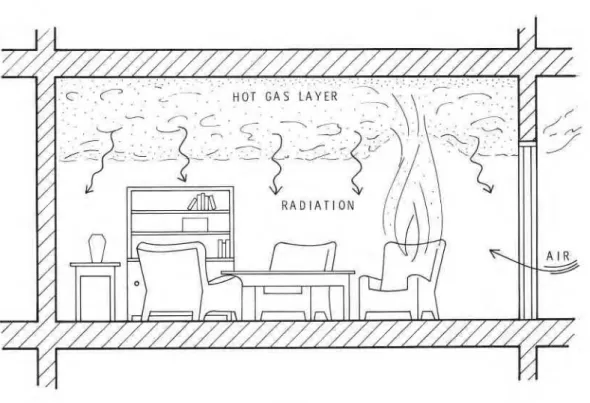
source item burns in approximately the same way as it would in the open. Then, as flames spread over the surface of the source item, and perhaps to other con- tiguous items, the process of burning be- comes influenced more and more by the environment. Heat is fed back from the surrounding objects, especially from the compartment boundaries, and augments the rate of burning. With increasing rapidity a layer of hot smoky gases builds up below the ceiling. As Fig. 1 shows, intense radiant energy fluxes originating mainly from the hot ceiling and the adjacent smoke layer gradually heat up the contents of the com- partment and, upon reaching a level of about 1.7 to 2.1 W/cm"Fang 1975), ignite, in quick succession, all combustible items within; flashover occurs. [Experi- mental studies (Gross 1974; Hagglund et al. 1974) indicate that the attainment of a tem- perature of 500 to 600 C by the hot gas lay- er can also be regarded as a flashover cri- terion.]
A few fire "scenarios" of practical in- terest were recently surveyed by Benjamin (1976). He pointed out that combustible wall and ceiling linings may or may not play a substantial part in the chain of events leading to flashover, depending on the total fire load, distribution of the com- bustible items, and location and size of the source fire. On the one end of the safety scale are densely furnished rooms with large combustible contents (i.e., with high "fire l o a d ) and with items of high specific surface (to be discussed). The time to flashover for such rooms is very short, re- gardless of the nature of the lining ma- terials. On the other end of the scale are the sparsely furnished rooms. For these a combustible wall lining may become the principal path of fire spread and, therefore, the presence or absence of such linings may mean the difference between short flash- over time or no flashover at all. Naturally, for rooms lined with combustible materials the location and size of the source fire are of extreme importance. Bruce's experi- ments (1959) showed that the nature of the walls had very little effect on the time to
BUILDING DESIGN AND FIRE HAZARD
FIG. 1. Pre-flashover fire.
flashover when no combustible item was closer than 18 inches to the walls.
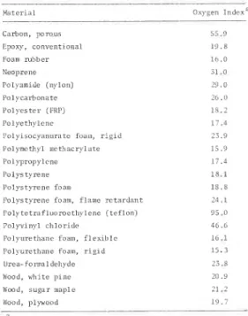
The so-called "oxgyen index" method (Fenimore and Martin 1966; ASTM D2863- 74) provides a convenient way of arrang- ing various materials according to their liabilities of becoming sources of fire. (Table 1 gives the oxygen index for a few common materials.) The oxygen index does not, however, reflect the increased or de- creased liability associated with the shape, surface texture, and orientation of an ob- ject. I t is common knowledge that an ob- ject with large "specific surface area" (ex- ternal surface area per unit weight) is more easily ignited than a bulky object. It takes considerable effort to ignite a massive piece of wood furniture, whereas other objects of cellulosic materials, for example cotton fabric or sheets of paper, flame up quite readily.
Unfortunately, there is no reliable test method to date that could be used to pre- dict the burning characteristics of various materials once the fire has grown beyond
its incipient stage. Benjamin (1976) doc- umented with data borrowed from a report by Castino et al. (1975) that flamespread ratings derived from standard tunnel tests (ASTM E 84-76a) do not necessarily place the various lining materials in the correct order as far as the hazard of early flashover is concerned. Friedman ( 1975) noted that some fire-retarded panels, though not read- ily ignitable, once ignited spread flames just as fast as nonretarded panels.
These findings come as no surprise to those familiar with fire-performance tests. For the sake of ensuring the commensur- ability of the results, i.e., the ability of ar- ranging the results on a unique quality scale, these tests are conducted under a specified set of conditions which rarely, if ever, coincide satisfactorily with those aris- ing in actual fires. For example, the rate of flame spread is known to depend signifi- cantly on the radiant energy flux to the lin- ing material (Alvares 1975; Fernandez- Pello 1977). There is evidence ( Tewarson and Pion 1976) that strong energy fluxes,
TABLE 1. Oxygen index for a few common ma- terials (Hilado 1969, Tsuchiya and Sumi 1974) M a t e r i a l Oxygen 1ndexa Carbon, porous Epoxy, c o n v e n t i o n a l Foam r u b b e r Neoprene Polyamide (nylon) P a l y c a r b o n a t c P o l y e s t e r (PRF) P o l y e t h y l c n c l ' o l y ~ s o c y a n u r a t e foam, r i g l d Polymcthyl m c t h a c r y l a t e Polypropylene I'olystyrene P o l y s t y r e n e foam
I'olystyrene foam, flame retardant I ' o l y t e t r a f l u o r o e t h y l e n e ( t e f l o n ) P o l y v i n y l c h l o r i d e Polyurethane foam, f l e x i b l c I ' o l > u r e t h a n e foam, r i g l d Urea-folmaldehyde hood, w h i t e p l n e IVood, s u g a r maple Wood, plywood
a ~ x y g e n i n d e x = minimum oxygen c o n c e n t r a t i o n , expressed as volurne p e r c e n t , r e q u i r e d t o s u p p o r t f l a m i n g combustion
such as those arising in real-world fires, may completely upset the ranking of vari- ous lining materials by standard tunnel tests. If it is realized that the level of ther- mal radiation is only one of the numerous factors that may have important bearing on the phenomenon of flame spread, one will recognize the problems associated with deriving meaningful but simple perfor- mance tests.
The most important requirements that must be followed to prevent fast develop- ing fires are covered in building codes, which regulate what can be built into a building, and fire codes, which control what can be brought into it. Typical items that fire codes are concerned with include movable partitions, floor covering and decorating materials, drapes, and curtains, for use in buildings of dense occupancy. These items must be subjected to various
performance tests (Sumi 1975) that will, it
is hoped, yield some idea of their propensi-
ties for becoming ignition sources and prop- agating fire.
The building code regulations that have some bearing on the time to flashover are those that restrict the use of combustible lining materials. Conventionally, interior finishes having flame spread ratings higher
than 150 are not allowed in buildings of
dense occupancy in many parts of North America. Further restrictions are imposed on the flamespread ratings of linings used in exits. A recent addition to building codes requires that foam plastics, which have been known to spread fire much faster under realistic fire conditions than in per- formance tests, be covered air-tight with nonfoamed linings.
The safety of a building can be improved further by circumspect design. The build- ing designer knows the intended use of the building and, therefore, has at least a rough idea of the types of articles that may be brought into the various compartments up- on completion of the building. He can add valuable minutes to the time to flashover by avoiding extensive use of combustible linings in those compartments that are most likely to be furnished with fabric-covered (upholstered) items, or in which clothing articles are kept or stored. He can further heighten the level of fire safety by pro- viding closets and built-in cabinets for the storage of cloth and paper products. In the design of theatres, lecture rooms, atriums, lounges, etc. he can specify slightly ele- vated or recessed walk-ways or built-in planters along walls that are to be lined with combustible materials, and thus pre- vent the occupants or interior decorator from placing upholstered furniture close to those surfaces.
In closing this subject, it may be appro- priate to mention briefly the sprinkler sys- tem, because its chief function is to prevent incipient fires from reaching the flashover stage. Except for buildings with very large uncompartmented spaces, the use of sprin- kler system is an optional measure, but its use is often rewarded by the reduction of other building code requirements and by
BUILDING DESIGN AND FIRE HAZARD
131
of designing a sprinkler system are well known (Tryon and McKinnon 1969) and will not be discussed here.
THE SMOKE PROBLEM
Fire statistics reveal (Berl and Halpin 1976; HMSO 1971; Thomas 1974) that more people die in burning buildings from in- halation of toxic fire gases than from heat- inflicted injuries. Even in those deaths that are caused by burns, smoke is often a con- tributing factor; dense smoke obscures the vision of the occupants and prevents them from reaching safety.
Many clauses in building codes relate to facilitating escape from fire-stricken build- ings. Regulations cover the width of exits as a function of occupant concentration, distance between exits, access routes to exits, location and illumination of exit signs, and the maximum length of dead-end cor- " ridors. In addition, restrictions are grad- ually introduced on the use of materials that have a propensity for high smoke gen- eration. However. efforts to ~ r o v i d e a ra- tional basis for restricting tce use of the worst smoke-producing materials are ham- pered by two difficulties. The smoke-pro- ducing characteristics of most materials de- " pend quite substantially on the temperature and oxygen concentration of the surround- ing atmosphere (Tsuchiya and Sumi 1974) as well as on the rate of flow of air past the burning object (Gaskill 1973; Robertson 1973); consequently those materials that prove poor performers in laboratory tests may be acceptable under actual fire con- ditions, or vice versa. The other difficultv is that' processes introduced to retard thk flame-spreading characteristics of lining materials are often responsible for increased smoke production.
So far there has not been any attempt to restrict the use of materials on the basis of their propensities for generating toxic de- composition or combustion products. The most likely reason is that carbon monoxide, which may be produced by any material as a result of incomplete combustion, is still believed to be the only toxic gas worth
consideration. Accumulated data (Sumi and Tsuchiya 1975) indicate, however, that other toxic gases such as hydrogen cyanide, hydrogen chloride, nitrogen dioxide, and sulfur dioxide mav be the cause of fire deaths or injuries more often than is com- monly believed.
To ensure the safety of the occupants, the installation of fire detectors and fire alarms has been made mandatory in certain build- ings, mainly those of high occupant con- centration. In addition, in buildings with air circulating systems, the installation of smoke detectors in the main ducts is also required. Detection of smoke in the main return duct is followed by the shutdown of the return fan and by the actuation of the fire dampers of the duct system.
Unfortunately, dispersion of fire gases in a tall building is possible even after shut- down of the air-handling system. The smoke can be carried by natural air cur- rents to far places in the building. There are documented cases of hundreds of deaths caused by smoke inhalation at large dis- tances from the location of fire.
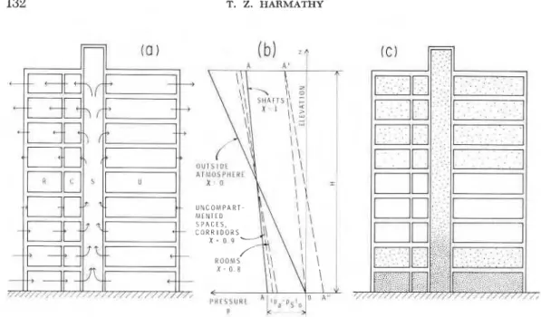
Air currents that disperse fire gases throughout the building develop as a result of the "leakage" of the outside walls of the building, and are induced by temperature differences between the interior and ex- terior atmospheres. For the latter reason, they are strongest during the winter heat- ing season. Figure 2a illustrates schemat- ically the dominant air currents in a nine- storey office building in the winter (with the air-handling system shut down). The building is shown to consist of four types of spaces: rooms ( R ) , corridors ( C ) , un- compartmented spaces ( U )
,
and stairwells and elevator shafts, referred to here jointly as shafts ( S ) . If the leakage characteris- tics of the outside wall are uniform, the in- filtration of air takes place below the mid- height of the building. After passing through various partitions, it enters the shafts, rises to the upper floors of the build- ing, moves toward the outside wall, and ex- filtrates to the outside atmosphere. Be- cause of the important role the stacklike - shafts play, the phenomenon is often re-FIG. 2 . Illustration of smoke problem in a 9-storey office building ( a ) Air currents, ( b ) Pressure
distribution, ( c ) Smoke distribution (fire on first storey).
ferred to as air movement by "stack effect" or "chimney effect." (The small air cur- rents that rise from storey to storey through the ceilings are not taken into account in the present discussion. )
The rate of air flow depends on the leak- iness of the outside walls and the various interior partitions of the building. Since the flow through small holes or gaps can be treated as flow through orifices, it is usual to characterize the leakiness of a building element by its "equivalent orifice area," a, which is the aggregate area of (often in- visible) holes, cracks, gaps, etc., referred to unit area of the building element. An anal- ysis of the situation illustrated in Fig. 2a requires information on three of these equivalent orifice areas: a,, that for the outside walls, a,, that for the corridor-room partitions, and a,, that for the shaft-corridor partitions.
The direct causes of air movement in a building are, naturally, the pressure differ- ences that exist between the constituent spaces of the building. Experimental stud- ies of heated multistorey buildings (Tam- ura and Wilson 1966, 1967) indicate that the pressure distribution along the height
of a simple multistorey building can be represented by a series of straight lines, as shown in Fig. 2b. (In reality, the lines for rooms, corridors, and uncompartmented spaces show slight discontinuities at the ceiling of each storey.) They can be de- scribed by the following equation:
P - pa = -gB(l/Ta - l/T,) (H/2 - Z ) X , (1)
where pa, the pressure of the outside atmo- sphere, is
provided that its value at x = 0 is taken as the reference pressure level. For conve- nience pressures are expressed in lb/ft h2. To obtain values in inches of water, multi- ply values in lb/ft h2 by 4.61 x 10-lo.
If
x
= 0, Eq. ( 1 ) obviously describes the pressure of the outside atmosphere. Withx
= 1, the variation of the pressure in the shafts, p,, is obtained. The values ofx
for the other three types of building spaces namely XR (for rooms), X O (for corridors),and
xu
(for uncompartmented spaces) can be calculated if the three equivalent orifice areas, a,, a,, and a, are known. In general, however, it is sufficiently accurate to useBUILDING DESIGN AND FIRE HAZARD 133
the following values: X E = 0.8, xc = X U = 0.9.
Since a, is usually much smaller than either a, or a,, it is permissible (as well as convenient) to assume that the only resis- tance to the movement of air is that offered by the outside walls of the building. With this assumption, the total rate of air infiltra- tion can be calculated as follows ( McGuire and Tamura 1975) :
Surveys of the leakage characteristics of ex- terior walls of tall buildings (Tamura and Wilson 1967; Tamura and Shaw 1976) in- dicate that, for lack of more accurate in- formation, a, = 0.0005 ft2/ft2 is a reason- ably conservative selection.
If fire breaks out below midheight of the building, the air currents rising in the shafts carry the smoke and distribute it to the compartments on the upper levels. Figure 2c shows the pattern of smoke distribution in the nine-storey building 10 to 15 min after the outbreak of fire on the first floor. (The smoke contamination of the storey above the fire floor is caused by vertical leakage currents mentioned earlier.)
The most obvious step the building de- signer can take to alleviate the smoke prob- lem is to avoid specifying lining materials that are known to be heavy smoke pro- ducers or that generate highly toxic decom- position and combustion products. Yet, this "passive" method of defence is rarely suf- ficient. From among the "active" methods three will be discussed here briefly: smoke dilution, provision of refuge areas, and building pressurization.
In milder climates, where the role of stack effect in smoke dispersion may not be sig- nificant, the technique of diluting the smoke is often used in keeping certain vital parts of the building, such as lobbies and stairwells, relatively free of smoke. It is believed (McGuire et al. 1970) that dilu- tion with fresh air in a 100 to 1 proportion
I will ensure safe conditions with respect to
both visibility and toxicity. The informa-
'
tion needed for the design of smoke dilu-tion systems includes the equivalent orifice area for the boundaries of the space to be kept smoke-free and the rate of smoke gen- eration by the fire. (The latter can be esti- mated as described by Harmathy 1972.)
Detailed studies have revealed (Gal- breath 1969; Pauls 1975) that the time for evacuating a building in case of fire is ap- proximately proportional to the building height and, depending on the occupant con- centration, may take much longer than the expected duration of an average fire. Con- sequently, complete evacuation of a build- ing above a certain height, say 10 to 15 storeys, does not seem practicable. The danger of exposing the occupants to smoke can be greatly reduced by providing pres- surized refuge areas, preferably in the vicinity of a stairwell, where the occupants can stay in relative safety for the duration of the fire. The required rate of air supply to these areas is not likely to be determined by the leakage characteristics of its bound- aries, but rather by the need for maintain- ing tolerable conditions for the assembled occupants. The required minimum flow rate of fresh air is 15 ft3/min per person (ASHRAE 62-73).
The most effective way of preventing the spread of smoke is to pressurize the entire building or some major parts of it. Smoke travel through the shafts to the upper storeys of the building is eliminated if the pressure everywhere in the building, or at least in the vertical shafts, is raised above that of the outside atmosphere. This can be accomplished by supplying air to the in- terior at a rate sufficient to shift the pres- sure distribution in the shafts (see line A-A in Fig. 2b) to a new position (line 0-A') which is characterized by the equality of the internal and external pressures at the ground floor level ( a t z = 0). The required rate of air supply is (McGuire and Tamura
1975).
i.e., roughly three times the rate of infiltra- tion of air into the building under normal conditions. As Fig. 2b shows, the pressure difference, Ap, against which the supply
between the pressure of the outside atmo-
sphere and shaft pressure on the ground The curve shown in Fig. 3 is typical of
floor level. Thus, from Eq. ( 1 ) with z = 0. the temperature history of a fire confined
to a single compartment and unattended
AP = ( P , - P ~ ) , by fire fighters. During the growth period
= g B (l/T, - l/T,) H/2. ( 5 ) of the fire the temperature of the compart-
ment gases is grossly nonuniform (see Fig.
There are two ways achieving
1 ) and the average temperature increases
pressurization. The popular slowly. At flashover the windows break
is converting the air-handling system of the
and the period of "fully developed fire" sets building to emergency operation and vent-
in. It is characterized by much higher tem- ing the fire floor (Tamura et al. 1970). The
peratures and improved uniformiq in the
conversion entails the shutdown of the re-
spatial distribution of temperature. The turn and exhaust fans of the system, to-
temperature becomes nonuniform again
gether with their associated branch and
and drops steadily as the fire enters its third outside dampers. This method, however,
period, the "decay" period, during which has some pitfalls (Tamura and McGuire,
1973). the flames die out and the charring remains
Pressurization can be more conveniently of the fuel oxidize.
achieved by injecting outside air into all Because professional help by fire-fighters
must not be taken for granted, the building shafts at the top of the building. Additional
designer has to accept responsibility for us- advantages (and savings in energy con-
sumption can be gained by preheating the ing the best available knowledge and tech-
air to only slightly above the 32 F level niques to ensure that a fire, no matter
where it may break out, will remain local- (provided that the outside temperature is
below the freezing point). As the cool air ized and relatively benign. As roughly 70%
of the fuel energy is released during its fully lowers the temperature in the shafts and
developed period, the characteristics of fire parts of the building, the pressure in the
during this period are obviously of utmost
building further increases (see A'-A'' in
Fig. 2b) and the flushing out of smoke from importance in planning a defence.
the building is accelerated. It is traditionally held that a building
subdivided by fire-resistant elements into The discussion of smoke control tech-
niques has been restricted here to the sim- reasonably sized compartments provides the
best assurance against destructive fires. plest high-rise buildings, those with uni-
form compartmentation and with shafts While there is little quarrel about the merits
that run the full height of the building. In of fire-resistant compartmentation, the
more complex situations the design is rarely method of deciding on the required fire
resistance of the dividing elements and the possible without a computer-aided analysis
(Barrett and Locklin 1968; Tamura 1969; way of determining it have come under in-
Wakamatsu 1976). Moreover, even for creasing criticism.
simpler buildings, invoking the computer The standard fire resistance test (ASTM
may be necessary if building pressurization E 119-76) is still the most widely accepted
way of evaluating the fire-resistant quality is combined with other techniques (Tam-
ura 1970; Fung and Zile 1975). of building elements. Unfortunately this test
A supplement to the National Building suffers from the same defect as most other
fire tests standards, namely that for the sake
Code of Canada Comm' On
vt'
of ensuring commensurability of the test
Code 'ontains an results on a unique quality scale, the test
survey of measures for providing fire safety conditions are idealized to an unjustifiable
in high buildings. Some of them are just extent. B~ scrutinizing the way the stan-
common-sense solutions and impose very dard tests are conducted and the test results
BUILDING DESIGN AND FIRE HAZARD 135
0 TIME
FIG. 3. Temperature history of a typical fire.
of fire resistance testing is based on the following four assumptions:
1 ) the severity of fire in a compartment is uniquely determined by the fire load; 2 ) the fire always develops in a definite manner characterized by a unique tem- perature-time curve;
3 ) the spread of fire is due to thermal or structural failure of an element (wall, floor, or ceiling) of the compartment boundary; and, therefore,
4 ) structural failure because of exposure of a boundary element from two sides is not possible.
Whereas the fallacy of the first two as- sumptions is clearly recognized now, and they are gradually being eliminated from modern practices of fire resistance evalua- tion (Pettersson et al. 1976), the inade- quacy of the third and fourth assumptions is still not fully realized.
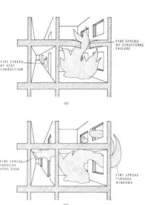
Even though building elements may oc- casionally fail in ways assumed by the phi- losophy of fire resistance testing, namely by conduction of heat through, or collapse of, one or more boundaries of the com- partment on fire (see Fig. 4a), in the vast majority of cases the spread of flaming com- bustion is a convective-radiant process. The flames are driven by pressure differ- ences from one compartment to another, either horizontally, mainly through doors left open by the escaping occupants, or ver-
F L U E S P R I A D B Y F l R U ~ T l I P l L I h l l l t l l i F l R E S P I B Y H E A T C O N D U C l i l l F l R E T H R O O P E N
FIG. 4. Mechanisms of fire spread ( a ) Mecb- anisms implied by the philosophy of fire testing
( b ) Actual mechanisms.
tically through poorly fire-stopped open- ings and by flames issuing from windows and then jumping to the storey above (Fig. 4b). Consequently, the fact alone that a building is well compartmented and the compartment boundaries are fire resistant (in the conventional sense) is no assurance against fire spread.
Once the fire has spread (horizontally or vertically) to a neighbouring compartment, the building element, wall or floor, that forms the common boundary of the two compartments becomes exposed to fire on both sides, a condition not considered in the standard test practices. Consequently, an element judged from a standard fire test as sufficiently fire resistant may collapse in a real-world (spreading) fire.
Because, as discussed, the lack of provi- sion for two-sided fire exposure is only one of several weaknesses in the standard fire resistance test procedure, the current prac- tice of providing safety is somewhat illu-
fully developed (postflashover) fires are fairly well understood by now, and it is pos- sible to devise truly effective measures against destructive fires.
From an analysis of the results of hun- dreds of compartment burnout tests (Kawa- goe, 1958; Gross and Robertson 1965; Butcher et al. 1966, 1967) and some ear- lier theoretical studies (Kawagoe 1967, Thomas et al. 1967; Magnusson and Thelandersson 1970), the following three parameters have been introduced to char- acterize the "severity" (destructive po- tential) of fully developed fires (Harmathy 1972): its duration, r (see Fig. 3 ) ; the average temperature of the compartment gases, T,; and the "effective heat flux," q ~ , i.e., the average heat flux that penetrates the compartment boundaries. All three de- pend primarily on two variables, the total "fire l o a d (the amount of combustibles in the compartment), G, and the rate of entry of air into the compartment (ventilation) U,. T , and qE also depend, to a lesser de- gree, on the size of the compartment and the thermal properties of the lining ma- terials.
If the doors remain closed and air enters only through the broken windows of the compartment,
As long as the fire load consists predom- inantly (in 85 to 90%) cellulosic materials in the form of ordinary furnishing items, the ratio U,/G determines the main char- acteristics of the fire. If U,/G is less than a critical value, ( U,/G)
,,
(equal to about 18.2 h-l), the rate of burning is roughly proportional to U,, and the fire is referred to as "ventilation-controlled." If, on the hand, U,/G 3 ( U,/G),,,
the rate of burn- ing is proportional to G; the fire is "fuel- surface-controlled."The duration of fully developed fire can be calculated from the following equations
(Harmathy 1972) :
for ventilation-controlled conditions
I t is important to note from Eq. ( 8 ) that for fuel-surface-controlled conditions, the dura- tion of fully developed fire (for conven- tional furnishing) is very short, about 19 min (0.314 h ) , and independent of the fire load and ventilation.
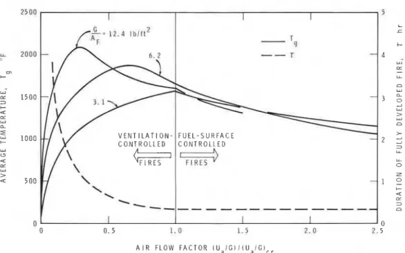
Unfortunately, the calculation of the two fire severity parameters, T , and qB, is some- what more complicated. I t involves the simultaneous solution of two equations [Eqs. (51) and (62) in Harmathy 19721. Figure 5 shows the variation of the dura- tion of fully developed fire, T, with the "air flow factor," defined as ( U,/G)
/
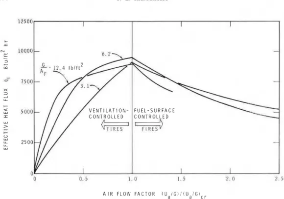
( U,/G),, as calculated from Eqs. ( 7 ) and ( 8 ) . I t also depicts the dependence of the tem- perature, T,, on the air flow factor, at three values of the "specific fire load," G/Ap (where AR is the floor area of the com- partment). In Fig. 6 the variation of the effective heat flux, q ~ , is plotted against the air flow factor for the same three values of the specific fire load. Although the curves of T , and qn relate to a particular set of conditions (described in Butcher et al. 1966, 1967), they can be regarded as typical. Attention is called to the fact that the highest temperatures usually occur at relatively low air flow rates (in other words, under ventilation-controlled conditions), whereas the maxima of the effective heat flux always coincide with ( U,/G),.
The designer, guided by statistical data on specific fire load in various occupancies (Witteveen 1966; Baldwin et al. 1970; Nils- son 1970; Berggren and Erikson 1970; Cerberus Alarm 1971; Bryl 1975; Cul- ver 1976) and by the preceding dis- cussion, can make a fair estimate of the fire severity parameters for all compartments of the building under design. Once this in- formation is available, he can proceed with specifying for each building element the re- quirements that will ensure its satisfactory performance in case of fire.
A clear distinction must be made be- tween "key structural elements" and "divid- ing elements." Key elements are those, the
BUILDING DESIGN AND FIRE HAZARD 137 I I I - T 9
-
--
T - V E N T I L A T I O N - F U E L - S U R F A C E-
I \ --,,, , ,,,,,,-,,, -I I I A I R F L O W F A C T O R ( U , I G ) I ( U , I G l c ,FIG. 5 . Duration of fully developed fire and average fire temperature (the latter for a specific set of conditions )
.
collapse or major deformation of which may endanger the stability of the building. It is advisable that the appropriate fire protec- tion of each of these key elements be eval- uated from comprehensive heat flow stud- ies, similar to those outlined in Harmathy ( 1976a, 1977). If there is a possibility, how- ever remote, that the element may become exposed to fire on both sides, two values of the effective heat flux, q ~ , and of the period of fully developed fire, r (one for the com- partment under study and one for the ad- jacent compartment), will form the basic input information. All realistic possibilities of simultaneous and delayed exposure of the two sides to fire should be examined. Studies of this kind indicated that simulta- neous exDosure of the two sides does not &
necessarily represent the most adverse con- ditions; increasingly delayed exposure of the reverse side may create increasingly detrimental conditions.
Such scrupulous studies are not justified, however, in the case of simple dividing ele- ments that are not parts of the load-bearing network. Because, once the fire has spread
to its reverse side, a dividing element has no further role in the provision of fire safe- ty, there is no need for requiring it to with- stand fire from both sides. In fact, if U,/G for both adjacent compartments is higher than the critical value, 18.2 h-l, specifying a 30-min fire resistance (as evaluated from standard fire resistance test) is adequate. This claim is based on the finding that for fuel-surface-controlled fires the duration of fully-developed fire is only about 19 min
[see Eq. ( 8 )
1.
Figure 5 shows that not only are fuel- surface-controlled fires, short, but they de- velop at relatively low temperatures. The designer may, therefore, consciously aim at providing conditions that would favour fuel-surface-controlled fires. In other words, the designer has a certain degree of free- dom in designing the fire itself, as well as the protection against it.
Fuel-surface-controlled conditions are ex- pected to prevail if relatively large windows are selected, such that
FIG. 6. Effective heat flux (for a specific set of conditions).
[This relationship has been obtained by ex- pressing ( u , / G ) , in terms of window-area with the aid of Eq. ( 6 )
1.
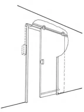
Although the possibility of fire spread must never be ruled out in the design for fire safety, the designer is well advised to use all available techniques to minimize the probability of spread. The simplest and most effective way of achieving this is specifying self-closing compartment doors. Several building codes have already made the use of self-closing doors mandatory in high-rise buildings. Unfortunately, hinged doors may present some problems if fire breaks out in one of the lower storevs dur- ing the winter heating season. ~ f i e r the windows of the fire cell are broken, it may be difficult or even impossible to open the corridor door because of the large pressure differences between its two sides. It would be more practical to use weight-operated sliding doors of some light construction. If
such doors are hung by rollers from a con- cealed rail and supported by two more rol- lers near the bottom, as shown in Fig. 7,
opening them at any pressure difference would require less force than that required to open a hinged door equipped with a clos- ing device at no pressure difference. Other solutions that offer similar advantages are also available (Williamson 1976).
A door that remains closed during the fire is an effective barrier not only against the spread of fire but also against the spread of smoke. A numerical example worked out for a 20-storey building, with the fire occurring in the winter in dne of the first- storey compartments, indicated that the rate of smoke spread is reduced by a factor of at least 30 by closing the door of the fire cell. Further reduction can be achieved by the application of a special material (Bad- ische Anilin) along the edges that would expand on heating to fill gaps around the door.
Vertical or horizontal spread of fire can often be traced back to the penetration of the floors or walls by plastic DWV (drain, waste, and vent) pipes and telephone or electric cables. Fire tests indicate (Mc-
BUILDING DESIGN AND FIRE HAZARD
Guire 1973, 1975; Orals and Quigg 1976) that it is sound practice to surround these pipes and cables with a noncombustible packing housed in a thin sheet steel sleeve extending beyond the surface of the floor or wall.
A systematic investigation conducted in Australia (Com. Exp. Build. Stn. 1971) confirmed the earlier British finding that 2-ft projections over the windows of a building do not prevent flames issuing through windows from curling back and igniting the storey above. It was found, however, that projections wider than 3-4 ft are effective in keeping the flames away from the face of the building and in reduc- ing radiation to the storey above to an ac- ceptable level.
Continuous balconies and open corridors can play a useful part in protecting build- ings against the vertical spread of fires. Un- fortunately, their use is rarely considered nowadays even for residential buildings,
because they cut down the natural daylight FIG. 7 . Self-closing sliding door. reachinn the interior. increase the building u u
costs, and may produce aesthetically unde- sirable effects.
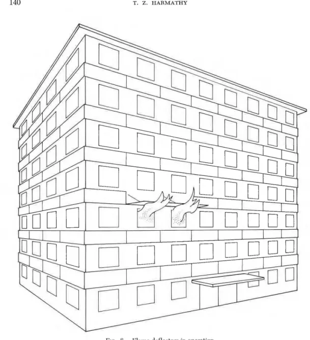
Simple "flame detectors" (Harmathy 1976b) can provide the same degree of pro- tection as continuous balconies and open corridors, at substantially lower cost and without the aforementioned drawbacks. They are light metal panels mounted above each window and held in vertical position by a fusible part, possibly a nut. The width of these panels is at least 3 ft 3 inches and their length equal to the window breadth plus about 4 ft. As Fig. 8 shows, the deflec- tor falls down to assume horizontal position when activated by flames issuing from the window below. Covered with baked-on enamel, or furnished with bronzed, im- printed surfaces, for example, the deflec- tors may be consciously applied to the building as decorative elements.
A high degree of fire safety can be achieved by a new technique referred to as "fire drainage" ( Harmathy 1976b). It uti- lizes the energy of fire in three ways: ( 1 ) by drawing air into the fire cell in quan- tities that ensure fuel-surface-controlled
conditions, i.e., short fire duration and rela- tively low fire temperature; ( 2 ) by keeping the pressure in the fire cell below the pres- sure levels prevailing in the neighbouring spaces; and ( 3 ) by removing the smoke and flames from the fire cell in a safe and or- ganized manner.
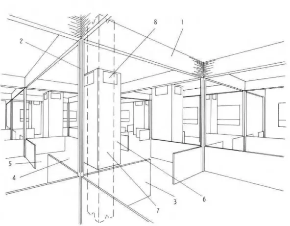
Figure 9 shows a large, uncompart- mented space equipped with a fire drain- age system. The ceiling is divided into many rectangular areas by a series of re- tracted fold-up drop curtains, 1, made of light-gauge metal and equipped with weightier bottom pieces. The purpose of these curtains is twofold: they restrict the spread of flames and smoke during the growth period of fire; and when activated by the fire, they slide down in grooves, 2, to floor skirting boards, 3, and surround the cell on fire, 4, leaving only four openings,
5, properly sized for controlled ventilation. There is a column, 6, in the center of each cell. A well-insulated "drainage duct," 7, runs the entire height of the building in the interior of the columns. Each duct has four "access gates," 8 (insulated on the duct
FIG. 8. Flame deflectors in operation.
I
side), near the ceiling on every storey, by tivation of the drop curtains, 1. The fire which it serves a number of cells located on gases enter the drainage duct, 7, and, by the successive storeys. These gates are nor- destroying the tensioning line, cause the mally closed by simple fusible parts. There release gates at the top to open. Not only are two or four "release gates" (not shown) are the gases and flames safely withdrawn at the top end of each drainage duct above from the building, but the suction created the roof level. They are held closed by the by the column of hot combustion products tension of a heat-destructible line extending in the duct creates a depression in the fire to the bottom of the duct. cell and thus prevents the dispersion of' As fire in the cell starts to build up, the smoke and fire to the neighbouring spaces. access gates, 8, open shortly before the ac- The design of the fire drainage system
BUILDING DESIGN AND FIRE HAZARD 141
FIG. 9. Uncompartmented space equipped with fire drainage system.
involves the calculation of the cross-sec- tional area of the drainage duct and the area of entry of air into the cell (the sum of the four openings, 5, in the floor skirt- ing boards). The procedure is described briefly by Harmathy ( 1976b).
Since operation of the fire drainage sys- tem does not rely on the availability of water and electricity at the time of fire (the charring remnants of the fuel can be extinguished with some chemical suppres- sant), its application may offer special ad- vantages in remote, poorly serviced com- munities, or with buildings the contents of which are sensitive to water damage. The disadvantage of the system is that with its use the normal loss expectancy is an entire cell and, therefore, it is not suitable for the protection of buildings with valuable con- tents.
CONCLUSIONS
Although the most important aspects of the design of buildings for fire safety are governed by building codes, a com- petent design team is capable of greatly increasing the level of safety beyond that provided by the stereotyped application of regulations, usually without any additional expenditures, or even at substantial savings to the builder. I t is extremely important to realize, however, that fire safety is not something that can be added on after com- pletion of the building plans. To be really effective, the problem of fire safety must be taken into account from the first step of architectural design.
Discussion in this paper was confined to the more or less conventional types of build- ings of residential, business, and institu- tional occupancies. With buildings erected
for housing large crowds a variety of other fire safety problems will inevitably arise (Phillips, 1974), many of them not covered adequately by building codes. The inclu- sion of a fire safety expert in the design of such buildings is not just a wise move, it is essential.
REFERENCES
ALVARES, N. J. 1975. Some experiments to de- lineate the conditions for flashover. Int. Symp. Fire Safety of Combustion Materials. Univ. Edinburgh, p. 375.
ASHRAE STANDARD 62-73. 1973. Standards for
natural and mechanical ventilation.
ASSOCIATE COMMITTEE ON THE NATIONAL BUILD- ING CODE. 1973. Measures for fire safety
in high buildings. National Research Coun- cil of Canada, NRCC 13366, Ottawa. ASTM DESIGNATION D2863-74. 1976. Standard
method of test for flammability of plastics us- ing oxygen index method. Annual Book of ASTM Standards, Part 35, p. 701.
ASTM DESIGNATION E 84-76a. 1976. Standard method of test for surface burning character- istics of building materials. Annual Book of ASTM Standards, Part 18, p. 652.
ASTM DESIGNATION E 119-76. 1976. Standard methods of fire tests of building construction and materials. Annual Book of ASTM Stan- dards, Part 18, p. 700.
BADISCHE, ANILIN- AND SODA-FABRIK, A. G. n.d.
Palusol fire-board. B557e-2.74.
BALDWIN, R., M. LAW, G. ALLEN, AND L. G. GRIF- FITHS. 1970. Survey of fireloads in modem
office buildings-Some preliminary results. JFRO, Fire Res. Note No. 808.
BARRET~, R. E., AND D. W. LOCKLIN. 1968.
Computer analysis of stack effect in high-rise buildings. ASHRAE Trans., 74, Part 11, 155. BENJAMIN, I. A. 1976. Development of a room fire test. ASTM STP 614, p. 300. Philadel-
phia.
BERGGREN, K., AND U. ERIKSON. 1970. Brand-
belastning i Kontorshus Statistisk Inventering och Utvardering. Stilbyggnadsinstitutets rap- port nr. 18: 1.
BERL, W. G., AND B. M. HALPIN. 1976. Fire-
related fatalities: An analysis of their demog- raphy, physical origins, and medical causes. ASTM STP 614, p. 28.
BRUCE, H. D. 1959. Experimental dwelling-room fires. Forest Products Laboratory Rep. No.
1941.
BRYL, S. 1975. Brandbelastungen im Hochbau. Schweizerische Bauzeitung, 93:243.
BUTCHER, E. G., T. B. CHITTY, AND L. A. ASHTON.
1966. Temperatures attained by steel in building fires. JFRO, Fires Res. Tech. Paper. No. 15.
, G . K. BEDFORD, AND P. J. FARDELL. 1967.
Further experiments on temperatures reached by steel in buildings. Paper 1, Proc. Symp. Fire Research Station, JFRO, p. 1.
CASTINO, G. T., J. R., BEYREIS, AND W. S. METES.
1975. Flammability studies of cellular plas-
tics and other building materials used for in- terior finish. File subject 723. Underwriters' Laboratories Inc.
CERBERUS ALARM. 1971. Fire load. Nov., p. 1. COMMONWEALTH EXPERIMENTAL BUILDING STA-
TION. 1971. Horizontal projections in pre-
vention of spread of fire from storey to storey. Australia, Rep. No. TR52/75/397.
CROCE, P. A. 1975. A study of room fire devel-
opment: The second full-scale bedroom fire test of the home fire project (July 24, 1974). Vols. I and 11, FMRC Ser. No. 21011.4, Fac- tory Mutual Research, Norwood, MA.
, AND H. W. EMMONS. 1974. The large-
scale bedroom fire test (July 11, 1973). FMRC Ser. No. 21011.4, Factory Mutual Re- search, Nonvood, MA.
CULVER, C. G . 1976. Survey results for fire loads and live loads in office buildings. Building Science Series 85, National Bureau of Stan- dards, Washington, DC.
EMMONS, H. W. 1977. Computer fire code
( 11). Harvard University, Div. Eng. Appl. Phys., Home Fire Project Tech. Rep. No. 20. FANG, J. B. 1975. Fire buildup in a room and the role of interior finish materials. NBS Tech. Note 879, National Bureau Standards, Washington, DC.
FENIMORE, C. P., AND F. J. MARTIN. 1966.
Candle-type test for flammability of polymers. Modem Plastics 43: 141.
FERNANDEZ-PELLO, A. C. 1977. Fire spread over vertical fuel surfaces under the influence of externally applied thermal radiation. Home Fire Project Tech. Rep. No. 19, Harvard Uni- versity, Div. Eng. Appl. Phys.
FRIEDMAN, R. 1975. Behavior of fires in com- partments. Intl. symp. Fire Safety of Com- bustible Materials, Univ. Edinburgh, p. 100. FUNG, C. W., AND R. H. ZILE. 1975. Evalua-
tion of smokeproof stair towers and smoke detector performance. National Bureau of Standards, Washington, DC. NBSIR 75-701. GALBREATH, M. 1969. Time of evacuation by
stairs in high buildings. Fire Fighting in Canada, February, p. 3.
GASKILL, J. R. 1973. Smoke hazards and their measurement; a researcher's viewpoint. J. Fire and Flammability 4:279.
GROSS, D. 1974. The measurement and correla- tion of fire growth in a room. Proc., Symp. on Full-Scale Fire Tests, Research and Develop- ment Center, Lancaster, PA, November 11-12. GROSS, D., AND A. F. ROBERTSON. 1965. Ex-
BUILDING DESIGN AND FIRE HAZARD 143
( Intl. ) on Combustion. Combustion Insti- tute.
HAGGLUND, B., R. JANSSON, AND B. ONNERMARK. 1974. Fire development in residential rooms after ignition from nuclear explosions. FOA Rep. C 20016-D6 ( A3), Forsvarets Forskning- sanstalt, Stockholm, Sweden.
HARMATHY, T. Z. 1972. A new look at com- partment fires, Parts 1-11. Fire Technology 8: 196,326.
.
1976a. Fire resistance versus flame spread resistance. Fire Technology, 12:290..
1976b. Design of buildings for fire safety, Parts I and 11. Fire Technology 12: 95, 219..
1977. Performance of building elements in spreading fires. Fire Research 1 ( 2 ) : 119- 132.HILADO, C. J. 1969. Flammability handbook for plastics. Technomic Publ. Co., p. 40. H.M.S.O. 1971. United Kingdom fire and loss
statistics. Her Majesty's Stationery Office, London.
KAWAGOE, K. 1958. Fire behaviour in rooms. Building Research Institute, Japan, Rep. No. 27.
.
1967. Estimation of fire temperature- time curve in rooms. Building Research In- stitute, Japan, Res. Paper No. 29.MAGNUSSON, S. E., AND S. THELANDERSSON. 1970. Temperature-time curves of complete process of fire development; theoretical study of wood fuel fires in enclosed spaces. Acta Poly- technics Scandinavica, Civil Engineering and Building Construction Series No. 65, Stock- holm.
MCGUIRE, J. H. 1973. Penetration of fire parti- tions by plastic DWV pipe. Fire Technology 9:5.
.
1975. Small-scale fire tests of walls penetrated by telephone cables. Fire Tech- nology 11:73., AND G. T. TAMURA. 1975. Simple anal- ysis of smoke-flow problems in high buildings. Fire Technology 11: 15.
, G. T. TAMURA, AND A. G. WILSON. 1970. Factors in controlling smoke in high buildings. ASHRAE Symp. Bulletin "Fire Hazards in Buildings," p. 8.
MODAK, A. T. 1976. The third full-scale bed- room fire test of the home fire project (July 30, 1975). Vol. 11, FMRC Ser. No. 21011.7, Factory Mutual Research, Nonvood, MA. NILSSON, L. 1970. Brandbelastning i Bostad-
slagenheter (Fire loads in flats). Rep. No. 34:1970, Nat. Swedish Institute for Building Research.
ORALS, D. L., AND P. S. QUIGG. 1976. Com- munication cable "Poke Thru" floor fire test. United States Gypsum Company, Des Plaines, IL.
PAULS, J. L. 1975. Evacuation and other fire safety measures in high-rise buildings. ASH- RAE Trans., 81, Part I, 528.
PETTERSSON, O., S. E. MAGNUSSON, AND J. THOR. 1976. Fire engineering design of steel struc- tures. Swedish Institute of Steel Construc- tion, Stockholm, Sweden, Publ. 50.
PHILLIPS, A. M. 1974. Fire protection of en- closed-mall shopping complexes. National Re- search Council of Canada, Division of Build- ing Research, Technical Paper No. 420 (NRCC 13976 ), Ottawa.
QUINTIERE, J. 1976. Growth of fire in building compartments. ASTM STP 614, p. 131. Philadelphia.
ROBERTSON, A. F. 1973. Tests indicate venting increases smoke for some polymers. Fire En- gineering, September, p. 97.
SMITH, E. E., AND M. J. CLARK. 1975. Model of the fire in a compartment. ASHRAE Trans., 81, Part I, 568.
SWMI, K. 1975. Requirements in Canada for fire safety of combustible materials. Intl. Symp. Fire Safety of Combustible Materials, Univ. Edinburgh, p. 55.
, AND Y. TSUCHIYA. 1975. Toxicity of de- composition ~roducts. J. Combustion Toxicol- ogy, 2:213.
TAMURA, G. T. 1969. Computer analysis of smoke movement in tall buildings. ASHRAE Trans., 75, Part 11, 81.
.
1970. Analysis of smoke shafts for con- trol of smoke movement in buildings. ASH- RAE Trans., 76, Part 11, 290., AND J. H. MCGUIRE. 1973. The pres- surized building method of controlling smoke in high-rise buildings. National Research Council of Canada, Division of Building Re- search, Technical Paper No. 394 (NRCC
13365 ) .
, J. H. M c G m , AND A. G. WILSON. 1970. Air-handling systems for control of smoke movement. ASHRAE Symp. Bulletin "Fire Hazards in Buildings," p. 14.
, AND C. Y. SHAW. 1976. Studies on ex- terior wall air tightness and air infiltration of tall buildings. ASHRAE Trans., 82, Part I, 122.
, AND A. G. WILSON. 1966. Pressure dif- ferences for a nine-storey building as a result of chimney effect and ventilation system operation. ASHRAE Trans., 72, Part I, 180.
, AND
-
.
1967. Pressure differences caused by chimney effect in three high build- ings and building pressures caused by chim- ney action and mechanical ventilation. ASHRAE Trans., 73, Part 11.TEWARSON, A., AND R. F. PION. 1976. Flam- mability of plastics. I. Burning intensity. Combustion and Flame 26: 85.
inhalation, fire gases, and related topics. Pro- ceedings of a Symposium on Occupational Health and Hazards of the Fire Services, Notre Dame University, South Bend, IN., January 11-13, 1974.
THOMAS, P. H., A. J. M. HESELDEN, AND M. LAW. 1967. Fully developed compartment fires: Two kinds of behaviour. JFRO, Fire Res. Tech. Paper No. 18.
TRYON, G. H., AND G. P. MCKINNON, eds. 1969. Fire protection handbook, Section 16, 13th ed. NFPA, Boston.
TSUCHIYA, Y., AND K. SUMI. 1974. Smoke pro-
ducing characteristics of materials. J. Fire and Flammability, 5:64.
WAKAMATSU, T. 1976. Calculation methods for predicting smoke movement in building fires and designing smoke control systems. ASTM STP 614, Philadelphia, p. 168.
WILLIAMSON, R. B. 1976. Automatic closing wide span fire-rated barrier-A new device for fire protection. Univ. California, Berkeley, March.
WITTEVEEN, J. 1966. Brandveilighed Staalcon- tructies. Centrum Bouwen in Staal, Rotter- dam, Holland.