Publisher’s version / Version de l'éditeur:
Transactions of Nonferrous Metals Society of China, 20, Suppl. 3, pp. s878-s882,
2010-09-16
READ THESE TERMS AND CONDITIONS CAREFULLY BEFORE USING THIS WEBSITE. https://nrc-publications.canada.ca/eng/copyright
Vous avez des questions? Nous pouvons vous aider. Pour communiquer directement avec un auteur, consultez la
première page de la revue dans laquelle son article a été publié afin de trouver ses coordonnées. Si vous n’arrivez pas à les repérer, communiquez avec nous à [email protected].
Questions? Contact the NRC Publications Archive team at
[email protected]. If you wish to email the authors directly, please see the first page of the publication for their contact information.
NRC Publications Archive
Archives des publications du CNRC
This publication could be one of several versions: author’s original, accepted manuscript or the publisher’s version. / La version de cette publication peut être l’une des suivantes : la version prépublication de l’auteur, la version acceptée du manuscrit ou la version de l’éditeur.
For the publisher’s version, please access the DOI link below./ Pour consulter la version de l’éditeur, utilisez le lien DOI ci-dessous.
https://doi.org/10.1016/S1003-6326(10)60599-7
Access and use of this website and the material on it are subject to the Terms and Conditions set forth at
Prediction of shear-related defect locations in a semi-solid casting
using numerical flow models
Pineau, Frédéric; D’Amours, Guillaume
https://publications-cnrc.canada.ca/fra/droits
L’accès à ce site Web et l’utilisation de son contenu sont assujettis aux conditions présentées dans le site LISEZ CES CONDITIONS ATTENTIVEMENT AVANT D’UTILISER CE SITE WEB.
NRC Publications Record / Notice d'Archives des publications de CNRC:
https://nrc-publications.canada.ca/eng/view/object/?id=1f19fcfd-625b-4df8-bedb-3d7c411c702b https://publications-cnrc.canada.ca/fra/voir/objet/?id=1f19fcfd-625b-4df8-bedb-3d7c411c702bPrediction of shear-related defect locations in a semi-solid casting using
numerical flow models
Frédéric Pineau, Guillaume D’Amours
National Research Council of Canada, Aluminum Technology Centre, 501 University Blvd, Saguenay, Qc, Canada, G7H 8C3
Received 31 March 2010; accepted 30 April 2010
Abstract: Contaminated surfaces of the feedstock materials in aluminum alloy casting processes often produce various types of defects
which can affect the tensile properties of the final products as well as their fatigue reliabilities. Semi-solid processing takes advantage of a much higher apparent viscosity of the die cast materials by limiting the risk of oxides formed at the free surfaces to become incorporated into the casting when the material is injected into the die. Most of existing semi-solid processes that use billets as feedstock material are however tied up with a different type of contaminated surface. During the injection phase, the external-skin on the periphery of the billet, which has been in contact with air and lubricant during the transfer in the shot sleeve, can be incorporated into the casting. When subjected to a heat treatment, the lubricant is decomposed and produces lens shape porosities. This might be a cause of reject for most structural parts. To avoid this kind of defects, the paths along which the billet skin evolves must be controlled during filling. In order to investigate the possibility of skin inclusion into cast parts during injection of the billet, a two-phase finite element mixture model is employed to model the metal flow. The formation of a skin on the periphery of the billet is modeled by setting an initial solid phase concentration profile in the radial direction. Microscopic observations of the real castings showed that the approach is able to model the shear layers and to predict the paths along which the ``lens porosity`` defects could be formed. An arbitrary Eulerian Lagangian (ALE) method is also investigated and appears to be very promising to follow the skin movement in the casting.
Keywords: oxide skin defects; two-phase flow; finite element modeling, ALE
1 Introduction
Aluminum casting processes are highly adaptable to the requirement of mass production and are nowadays widely used for many commercial products. Certain advantages are inherent to these processes such as obtaining complex near net shape parts with specific requirements such as good surface finish and good mechanical properties.
Semi-solid casting processes are employed when high integrity parts are required. Indeed, semi-solid processes provide during filling more regular flow fronts compared to high pressure (liquid) die casting processes and thus reduce the possibility of entrapping oxide skins into the part. Nevertheless, oxide film related defects are difficult to avoid in metal injection processes. These defects may take different forms and originate either from the melt preparation or from the filling phase, e.g. [1].
In many rheo-molding processes, the billet is obtained from liquid aluminum that partially solidifies before being injected into the cavity as a semi-solid material. During the billet preparation, the aluminum in contact with the container can form a skin around the semi-solid core. Meanwhile, the top circular surface of the billet remains in contact with air and is thus prone to oxidation. Oxides may also be introduced in the semi-solid billet when liquid aluminum is poured into the crucible but the latter case is not considered in this paper.
The billet is next inserted horizontally into the shot sleeve. Because of gravity, there is contact between the bottom part of the billet and the shot sleeve wall. Consequently, the heat transfer is greater there and yields a “skin” that may be partially solidified. The “thickness” of the skin depends on the time spent in the shot sleeve before the injection. The lubricant in the injection chamber lies at the bottom of the shot sleeve and gets in contact with the skin. When injected into the cavity, the contaminated skin will probably enter into the part and yield undesired defects.
During heat treatment of the part, the lubricant that contaminated the surfaces that were injected in the part, is decomposed and produces “lens shape” porosities as depicted in Fig. 1. On this figure, the defects are on the shearing plane, where they were formed, but they could also propagate downstream depending on the ensuing velocity field. These defects can have definitely detrimental effects on the part integrity. To limit any serious consequences, the distribution of the skin inside the casting must be controlled by properly directing the flow during the injection phase.
Fig.1 Porosity lens defects along a shearing plane
In this work, a method is presented to identify the paths followed by the contaminated skin in the semi-solid casting. This will provide a tool to predict potential defect locations and to design the gating systems accordingly.
2 Numerical simulation: problem statement
Different approaches have been employed in the past to track the oxide skins associated with die casting processes, e.g. ref. [1]. A kinematic approach has often been employed to track selected points initially located on a free surface. This type of approach permits to follow air entrapments and free surface folding which are usually related to the occurrence of oxide formation and thus can identify potential defect locations into the part
In the present case, the skin is not a free surface. It is initially in contact with oil coating on the shot sleeve wall. Observations have shown that the skin will generally enter into the part along a shearing plane of the flow field. This very thin partially solid skin-fluid interaction is complex and not easy to deal with numerically. The skin must be followed to control inclusion defects into the part. An analysis of this complicated non-Newtonian flow that occurs during semi-solid injection casting can yield useful insights to resolve the difficulty.
In the next section, a model is presented to predict the displacement of the skin with the flow and evaluates where potential defects could be located. An arbitrary Lagrangian-Eulerian (ALE) approach is also presented. The latter approach has many interesting features that could be very helpful in a near future to accurately follow the oxide surface fragments and to optimize semi-solid gating systems.
3 Finite element model
As a first approximation, the flow resulting from the injection of a billet with a skin is modeled using a two-phase mixture approach. Three-dimensional modeling of the flow of a two-phase mixture is based on conservation of mass, momentum and solid volume fraction for an incompressible fluid. Derivation of the mixture conservation equations are detailed in reference [2]. The complete finite element model used in this work is described in reference [3]. The constitutive behaviour of the semi-solid material is given by a
Frédéric Pineau, Guillaume D’Amours Trans. Nonferrous Met. Soc. China 17(2010) s816
power-law relation from Orgéas et al. [4] which relates the local viscosity of the semi-solid material to the shear-rate and temperature:
1 n o c
γ
µ µ
γ
−=
ɺ
ɺ
(1)In this paper, the dependency of o and n to the solid
fraction has been removed to prevent the freezing of high solid fraction areas such as the ones used to represent the skin (otherwise no movement is possible with the mixture formulation). The following parameters have been set in equation (1).
Table 1: Model parameters
μ
on
7.2445 Pa.s 0.4955 cγ
ɺ
1.0 /sTo represent the “skin” on the billet surface, the solid fraction distribution is set along the billet radius as depicted in Fig. 2. The solid fraction is held constant (fs=0.5) in the core and increases to 0.6 near the wall. To simulate the presence of an oil film at the wall, the solid fraction is reduced to 0.1 near the wall location.
Fig. 2 Initial solid fraction distribution along the billet diameter
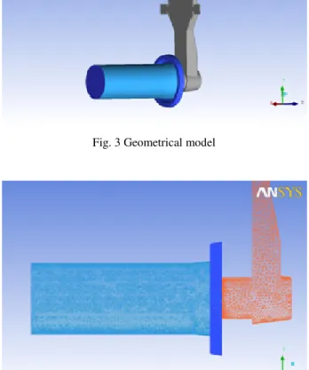
The geometric model of the shot sleeve and the cast part used in this study is presented in Fig. 3. The finite element mesh is shown in Fig. 4 and consists of 444142 four node tetrahedron elements, (81447 nodes).
The boundary conditions are “full slip” for the shot sleeve wall and “no slip” for the cavity walls, including the oxide ring. These conditions better reflect the physics of the billet that is injected in the shot sleeve. Full slip
conditions also prevent the skin from being stuck on the shot sleeve wall.
The inflow velocity (piston head velocity) is set to 300 mm/s. The movement of the piston is not accounted for, though this could certainly provide a better picture of the flow taking place. Instead, a constant feeding of the shot sleeve is set at the far end of the sleeve. The inflow solid fraction distribution is also set there and is similar to the initial solid fraction distribution inside the billet, except that it remains at 0.6 near the wall. This is used to better approximate the movement of the piston which somewhat pushes the “skin” along the walls. Isothermal conditions are assumed.
Fig. 3 Geometrical model
Fig.4 Finite element mesh of the shot sleeve
4 Simulation results
Calculations are performed with the finite element code for mold filling applications developed at the Industrial Materials Institute [5]. Simulation results with the two
Frédéric Pineau, Guillaume D’Amours Trans. Nonferrous Met. Soc. China 17(2010) s817
phase mixture model are depicted in Fig. 5 where the flow of the semi-solid material is shown at different times during the injection. The solid fraction distribution near the wall, (which approximates the contaminated surface: oxide skin and lubricants), is carried away into the feeding channel with the flow. As shown, most of the material near the wall remains in the shot sleeve as long as the oxide ring is not completely filled. When this happens, the “high” solid fraction skin begins to enter into the feeding channel along the shearing plane produced by the flow of semi-solid material through the constriction of the injection assembly. Note that when sheared, bands of higher liquid fraction generally appear in the semi-solid material which facilitates the inclusion of the skin into the casting, e.g. ref [6]. Evolution of the oxide skin further downstream will next depend on the channel geometry.
Fig.5 Material evolution near the wall
The low velocity region in the bottom portion of the “anvil” reservoir will generally trap the skins that come from the bottom part of the shot sleeve, (when not trapped by the oxide ring), see Fig. 6 (a), “L” region.
However, skin fragments that come from the upper part of the sleeve may be caught by the flow and carried away downstream, Fig 6 (a), “H” region. In the latter case, oxide skins do not have to follow a shearing plane once they have reached the channel and can show many different orientations in the part.
Fig.6 Velocity fields in the feeding channel
Note also that skin fragments that come from the upper part of the billet might be “less” contaminated by lubricants and will not necessarily yield a “lens” defect after heat treatment and are thus more difficult to detect. One of the problems with the mixture approach is that we follow a concentration field instead of a solid skin. The results are thus somewhat diffused and only give some information about the flow paths that are prone to be followed by oxide skins at the early time of the injection. Moreover, the latter approach assumes that the skin is continuous. In reality, it is not and it will be fragmented by the flow. Consequently, the mixture approach does
Frédéric Pineau, Guillaume D’Amours Trans. Nonferrous Met. Soc. China 17(2010) s818
not show exactly where defects could be located along those paths. To achieve that, an alternative method should be used. In the next section, we present an ALE approach, (Arbitrary Lagrangian Eulerian), which could be further developed to follow and locate the contaminated skin fragments into the casting.
5 ALE calculations
The following calculations have been carried out with the commercial software LS-DYNA. The latter has been originally designed to solve dynamics problems using Lagrangian formulations [7]. LS-DYNA, incorporates Eulerian formulations as well for fluid flow analyses. Moreover Lagrangian problems can interact with Eulerian problems inside the same model to treat fluid-structure interactions. The complete ALE formulation is presented in ref. [8]. An application of LS-DYNA to casting problems has been performed in ref. [9]. In this work, the software is used to evaluate the feasibility of the ALE approach to predict skin related defects in parts produced with semi-solid processing. These initial tests are carried out on a 2-D model. The problem is again isothermal. The skins are 0.25 mm thick and are modeled as an elastoplastic material with corresponding mechanical properties.
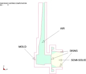
Fig. 7 LS-DYNA SSM casting model
Fig.7 shows the mold geometry with initial positions of the skins near the wall of the shot sleeve and in front of the billet. The semi-solid billet is modeled as a fluid-like material with a non-newtonian type behavior. Velocity boundary conditions are set at the inflow plane.
Frédéric Pineau, Guillaume D’Amours Trans. Nonferrous Met. Soc. China 17(2010) s819
Sequences of filling with skin tracking are depicted in Fig. 8. In (a), the semi-solid material hits the bottom of the “anvil” reservoir. The skin associated with the front of the billet impinges the “left” wall and remains there. Parts of the skin that were on the billet periphery enter in the channel section. The bottom skin leads over the skin from the top. As suggested by the mixture model, the bottom skin is carried by the vortex and remains there. The top skin is carried into the part by the flow, Fig.8 (b) and (c) and can yield potential defects in the part.
6 Conclusions
A finite element mixture model has been used to investigate the flow of a semi-solid billet “coated” with an “oxide skin”. The model can provide valuable information on the flow that takes place in the shot sleeve and can predict the paths by which the contaminated surfaces enter into the feeding channel. The model reproduces the shear layers that seem to facilitate skin inclusions in the casting. However, the mixture model is diffusive and the skin which is approximated by a layer of higher solid fraction tends to be diluted during the flow and disappears. Consequently, the model can be employed to indicate locations where shear type defects could be formed and propagate into the flow, as long as there is a shear layer. To overcome these limits, another approach was investigated and used: The ALE method of LS-DYNA. In this model the skin was represented as a solid entity with distinctive dimensions and mechanical properties. It can be transported, torn and folded according to the velocity field. Preliminary tests on a 2-D slice show that the model is very promising and could eventually be
used to predict shear defect locations in the casting. The mold and gating system could then be designed to avoid these defects. Further work is required to characterize properly the skin mechanical properties in addition of the semi-solid flow properties.
Acknowledgements
The authors want to express special thanks to their colleagues Marie-Ève Larouche and Dany Drolet for their help given in this work.
References
[1] YANG X, HUANG X, DAI X, CAMPBELL J, TATLER J: Numerical Modelling of the entrainment of oxide film defects in filling of aluminium alloy castings. International journal of Cast Metals Research 17 (2004) 321-331
[2] MANNINEN M, V TAIVASSALO On the mixture model for multiphase flows,VTT Energy, Finland 1996.
[3] PINEAU F, ILINCA F, HÉTU J-F: A mixture approach for semisolid metal mold filling simulations. MCWASP XI Proceedings Charles-André Gandin and Michel Béllet ed. (2006) 1063-1070 [4] ORGEAS L, GABATHULER J-P, IMWINKERLRIED TH,
PARADIES CH, RAPPAZ M: Modelling of semi-solid processing using a modified temperature-dependent power-law model. Modelling Simul. Mater. Sci. Eng. 11 (2003) 553-574
[5] ILINCA F, HÉTU J-F: Finite element solution of three dimensional turbulent flows applied to mold-filling problems. Int. J. Numer. Meth in Fluids, 34 (2000), 729-750
[6] PINEAU F, SIMARD G: Investigation of the primary phase segregation during the filling of an industrial mold with semi-solid A357 aluminum. Solid State phenomena, Vols 141-143 (2008) 635-640
[7] HALLQUIST, J.O., LS-DYNA theoretical manual, Livermore Software
[8] KIM, J.H. and H.C. SHIN, Application of the ALE technique for underwater explosion analysis of a submarine liquefied oxygen tank, Ocean Engineering 35, (2008), 812-822
[9] SHAPIRO, A.B., Heat transfer in LS-DYNA, 4th European LS-DYNA Users Conference, ULM, 2003