HAL Id: hal-02055845
https://hal.archives-ouvertes.fr/hal-02055845
Submitted on 4 Mar 2019
HAL is a multi-disciplinary open access
archive for the deposit and dissemination of
sci-entific research documents, whether they are
pub-lished or not. The documents may come from
teaching and research institutions in France or
abroad, or from public or private research centers.
L’archive ouverte pluridisciplinaire HAL, est
destinée au dépôt et à la diffusion de documents
scientifiques de niveau recherche, publiés ou non,
émanant des établissements d’enseignement et de
recherche français ou étrangers, des laboratoires
publics ou privés.
Electrical properties of double-wall carbon nanotubes
nanocomposite hydrogels
Jean-François Guillet, Zarel Valdez Nava, Muriel Golzio, Emmanuel Flahaut
To cite this version:
Jean-François Guillet, Zarel Valdez Nava, Muriel Golzio, Emmanuel Flahaut. Electrical properties
of double-wall carbon nanotubes nanocomposite hydrogels. Carbon, Elsevier, 2019, 146, pp.542-548.
�10.1016/j.carbon.2019.01.090�. �hal-02055845�
OATAO is an open access repository that collects the work of Toulouse
researchers and makes it freely available over the web where possible
Any correspondence concerning this service should be sent
to the repository administrator:
[email protected]
This is an author’s version published in:
http://oatao.univ-toulouse.fr/23156
To cite this version:
Guillet, Jean-François
and Valdez Nava, Zarel
and Golzio, Muriel and
Flahaut, Emmanuel
Electrical properties of double-wall carbon nanotubes
nanocomposite hydrogels. (2019) Carbon, 146. 542-548. ISSN 0008-6223
Electrical properties of double-wall carbon nanotubes nanocomposite
hydrogels
Jean-François Guillet
a,b, Zarel Valdez-Nava
c, Muriel Golzio
**,b, Emmanuel Flahaut
a,*aUniversit!e de Toulouse, CNRS, INPT, UPS, UMR CNRS-UPS-INP N85085, Universit!e Toulouse 3 Paul Sabatier Bat. CIRIMAT, 118 route de Narbonne, 31062, Toulouse cedex 09, France
bInstitut de Pharmacologie et de Biologie Structurale (IPBS) - UPS, CNRS, UMR 5089, BP 82164, 205 route de Narbonne, 31077, Toulouse cedex 04, France cLAPLACE, Universit!e de Toulouse, CNRS, INPT, UPS, Toulouse, France
a r t i c l e
i n f o
Keywords: Carbon nanotubes Polymer-matrix composites Electrical conductivity Smart materialsa b s t r a c t
The electrical behaviour of nanocomposite hydrogels and especially hydrogels containing carbon nanotubes is generally poorly understood. In this paper, we investigate the influence of double-wall carbon nanotubes (DWCNT) content on the electrical properties of agarose/DWCNT nanocomposite hydrogels.
These nanocomposite hydrogels are potential candidates as electrode materials for transdermal drug delivery by electropermeabilization. Both alternating current (AC) and direct current (DC) measurements at different voltage amplitudes were performed, as well impedance spectroscopy (1 Hze1 MHz). Data suggest a non-linear dependence of the conduction phenomena vs the applied electric field. From the current-voltage characteristics, the nanocomposite conduction phenomenon is narrowed to two possible mechanisms, a Schottky type or a Poole-Frenkel type. These findings are the first step towards the un-derstanding of the conduction phenomena in such complex nanocomposite structures, comprising DWCNT, water and the 3D polymeric network. The work described in this work is of much wider interest because this kind of nanocomposites may have many other applications, while the fundamental ques-tions about their electrical conductivity remain universal.
1. Introduction
The use of carbon nanotubes (CNT) to take advantage on their
electrical thermal and mechanical [1e3] properties has been
mainly possible through the development of polymer-based
nanocomposites [4]. Such biphasic nanocomposites (CNT and
polymer matrix) can be found in manyfields of application such as
aeronautics, automobile, aerospace or biomedical. When devel-oping such nanocomposites, several parameters can be taken into account such as the nature of the CNT, the synthesis method, the
nature of the polymer used and also the dispersion method [5]. In
this work, we focus on nanocomposite materials with a hydrogel matrix, which we have developed earlier for electrostimulated drug delivery through the skin, in which the encapsulation of CNT within
the polymer matrix can limit the potential risks related to the exposure of the users, hence reducing the CNT potential toxicity
[6,7]. However, the work described here is of much wider interest
as this kind of nanocomposite may have many other applications, while the fundamental questions about their electrical conductivity remain universal.
Nanocomposite hydrogels, also known as “hybrid hydrogels”, are defined by a 3D network crosslinked in a physical or chemical way (similar to hydrogels alone) and including nanomaterials from different nature: carbon nanoparticles (CNT, graphene,
nano-diamonds) [8,9], polymeric nanoparticles, inorganic nanoparticles
(hydroxyapatite, silica, silicates, iron oxide), metal nanoparticles (gold, silver). These nanoparticles interact directly with the poly-meric network, which allows new or improved properties
compared to the pristine hydrogel [10e12]. Nanocomposite
hydrogels are subject to numerous studies in the biomedical [9,13,14] or biotechnological field [11], with different applications such as tissue engineering [15,16], neuronal prosthesis [17], strain sensor [18], stretchable conductors [19].
Carbon-based electrically conductive hydrogels include three
*Corresponding author. **Corresponding author.
E-mail addresses:[email protected](M. Golzio),fl[email protected]
(E. Flahaut).
different phases with distinct properties: polymer (insulating ma-trix), CNT (conductor) and a liquid phase (water, pure or containing ions, which typically represents more than 95 wt % of the nano-material, and is integrated throughout the 3D polymeric network). The amount of water in the hydrogel defines the swelling ratio of the material (the capacity to integrate a liquid through the network) which is one of its fundamental characteristics. In turn, this swelling capacity influences the mechanical and electrical
properties of nanocomposite hydrogels [18,20]. Water in the
hydrogel generally induces the presence of ions that may contribute to the intrinsic electrical property, even if deionized water is used, because the polymer may itself contain counter-ions. In the context of the use of such nanomaterials for drug delivery through the skin by electropermeabilization, a fast rising voltage (hence, current) is applied to the skin in a single or pulsed sequence
for electroporation [21]. The nanocomposite hydrogels, used as a
drug reservoir, is within the path of the applied current, and its electrical properties are crucial to the transmitted voltage to the skin.
Some works on the electrical properties of pristine or composite
hydrogels [22e24] describe their conduction mechanism as mainly
dominated by ionic transport. While different methods could be
used (electrical impedance, conductivity meters) [20,22,25e28],
impedance spectroscopy is often the most widely used character-ization method [20,22,29]. Analysis of the results is based on the assumption that most of the hydrogel is composed of water, and results seem to indicate that it behaves as a liquid trapped in the volume of the samples. In the case of carbon-based electrically conductive hydrogels, the addition of CNT can greatly impact the electrical conduction, but examples in the literature are scarce
[20,29]. In our study, we have characterized such conductive
nanocomposite hydrogels containing DWCNT in conditions close to the actual operation conditions which would be used for trans-dermal drug delivery applications. Although a broad range of electrical characterizations was performed on agarose/DWCNT
nanocomposite hydrogels developed in our earlier works [30], we
have carried out here both AC voltage and DC voltage experiments in order to investigate the influence of the loading (0e40 wt % DWCNT) on the frequency domain and time domain response of the nanocomposite hydrogels. The results of the electrical charac-terization are discussed taking into account two possibilities, the first implying that the conduction phenomenon is dominated by the water (liquid-like) matrix, and a second one, in which, the carbon nanotubes could form a percolating network that would dominate the conduction phenomenon of such complex nano-composite materials.
2. Materials and methods 2.1. Fabrication of the device
Agarose (AG) Hydrogel was prepared using deionized (DI) water so that the final concentration of AG (SigmadAldrich Ref. A9539 -sulphate ions !0.15%.) was 2.5 wt/v. % (25 g L"1). After dissolution
of AG at 90#C, the solution was blended with a suspension of
dispersed DWCNT as described earlier [30] (the estimated amount
of DWCNT powder was dispersed in 50 ml of DI water for 20 min using an Ultra-Turrax model DI12 (IKA), followed by probe soni-cation for 1 h (1sec on/1sec off - 30% amplitude, probe diameter: 12 mm) at room temperature) in order to prepare nanocomposites containing DWCNT representing 10, 20, 30, 40 wt % of the agarose. The water content in the final nanocomposite hydrogels ranged between 97.5 wt % and 96.7 wt % depending on the amount of DWCNT and can thus be considered as constant whatever the composition. A control hydrogel sample without DWCNT
(CTRL-AG) was also prepared as a reference. Briefly, DWCNT were pre-pared by catalytic chemical vapour deposition using a catalyst with a Mg0.99Co0.0025Mo0.0075O elemental composition processed at
1000#C in a mixture of H2 and CH4 containing 18% of CH4 as
described in Ref. [31]. After synthesis, the catalyst was dissolved by addition of aqueous concentrated HCl. After thorough washing with deionized water, DWCNT were ready for use. Individual DWCNT have a diameter ranging between 1 and 3 nm and a length of the order of a few micrometres. However, they form bundles with a larger diameter (a few nanometres to a few tens of
nano-metres) and lengths which could reach 100
m
m [31]. Thesuspen-sions were then poured onto silicone moulds and cooled down to
room temperature (20e25#C) for 30 min. After cooling, agarose
nanocomposites hydrogels (DWCNT-AG) measured 1 cm diameter and were 0.2 cm thick; they were placed into a DI water (pH
5.5e3
m
S/cm) bath in the fridge for storage. The detailedprepara-tion of the nanocomposite hydrogels was described earlier [31] and
includes a combination of probe sonication and shear-mixing using an Ultra-Turrax. The electrical characterization of the samples containing 0 to 40 wt % of DWCNT (relative to agarose) was carried out in deionized water (after rinsing 5 times with DI water). Mea-surements were repeated on 2 different samples for each concentration.
2.2. Characterization
The electrical characterization of the nanocomposite hydrogels was carried out taking into account the possible scenario for their use as a drug delivery device. This includes their storage in deionized water to rule out any possible water evaporation before measurement. The measurements of the materials were carried out either in AC or DC conditions. Great care was taken to limit the evaporation of the water from the materials in order to avoid any experimental bias.
2.2.1. Frequency domain measurements (AC)
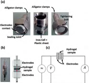
Electrochemical impedance spectroscopy (EIS) was our first choice to determine the electrical properties of our materials. The impedance meter used (VMP3 potentiostat Bio-logic S.A, France) was controlled by the EC-LAB software in the following conditions: 1 Hze1 MHz, 100 mV, and 10 points per decade (electrical circuit is shown inFig. 1c).
To perform the measurements we used a coaxial cell assembly
shown inFig. 1a, b. After having measured its thickness, the sample
was placed between two stainless steel electrodes (Fig. 1b). The
length of the cell was also measured with a caliper to evaluate the deformation of the sample when inserted into the cell.
2.2.2. Time domain measurements (DC)
To carry out electrical measurements we used an in-house
developed measurement cell shown in Fig. 2b. The sample
(Fig. 2a) is then deposited on a steel plate serving as a counter electrode covered with a circular electrode of platinum. The contact was made with a spring-retracting tip (in order to apply a constant force) between the plate and the alligator clamps, another tip was placed in contact with the stainless steel plate. To apply voltage and measure current through sample we used a source meter unit (SMU) that could apply the voltage with a simultaneous read-back of the applied voltage and current (Keithley 2410). Control of the SMU was done by a software interface (LabTracer 2.0, Keithley). Applied voltage to the sample ranged from 50 mV to 1.3 V with a minimum current sensitivity of 300 pA. First, a voltage step was applied to the sample, then the current passing through the sample was measured vs time (chronoamperometry). After the current was stabilized, a short circuit was applied for at least 2 min before
applying again a voltage step of different magnitude (Fig. 2c). 3. Results and discussion
3.1. AC measurements
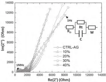
The complex impedance spectrum is related to the different polarization mechanism within the hydrogels such as conduction, dipole polarization or electronic polarization, but also related to other phenomena such as electrode polarization. When plotting the
Nyquist diagram for the samples containing DI water (Fig. 3), we
can observe that the AC conductivity increases with the amount of DWCNT.
On Fig. 3, we can observe several frequency-dependent phe-nomena commonly observed in Nyquist diagrams. Indeed, at high frequency, ions barely move; the impedance of a system depends on the resistance of the electrolyte, but also the resistance of the electrodes. When the frequency decreases again, the intersection of the plot with the x-axis indicates the resistance of the material. At
very low frequency, a straight line with a slope of 45#is observed,
corresponding to a capacitive phenomenon described as the War-burg impedance (diffusion).
By measuring the thickness, the diameter and using the data obtained by impedance spectroscopy, it is possible to determine the resistance from the Nyquist [20] and thus to obtain the resistivity of the sample by the following equation:
Fig. 1. a) Open measurement cell (Swagelok). b) Assembled measurement cell and mounting scheme of the cell (cross section). c) Diagram showing the measurement of a sample with two electrodes. (A colour version of this figure can be viewed online.)
Fig. 2. a) Photographs of a typical hydrogel sample (thickness: 2 mm; diameter: 10 mm). (b) Schematic representation measurement device. c) Data representing the current vs time (CTRL-AG sample). (A colour version of this figure can be viewed online.)
R ¼
r
Se Eq(1)To deduce the conductivity:
s
¼1r
Eq(2)With R the measured resistance,
r
the resistivity, e the thicknessand S the surface. In this work, the thickness or the diameter remained constant.
Indeed, the conductivity in deionized water for the reference
agarose hydrogel without DWCNT is 0.07 mS cm"1, while we
measured 0.27 mS cm"1(Table 1) for the sample loaded at 40 wt % of DWCNT. These values showed an increase in ionic conductivity but still did not demonstrate a possible percolation of DWCNT in the nanocomposite hydrogel.
A resistance and capacitance in parallel circuit, followed by a
Warburg impedance [32], could represent the model of the
equivalent circuit. Indeed, if the percolation threshold was reached, we should observe the same resistance value whatever the fre-quency (like measuring a metal), which was not the case here. This could indicate that an ionic conduction is still occurring alongside of the DWCNT. Nevertheless, the values of conductivity are very large compared with those of the deionized water (approximately
0.0004 mS cm"1). This, we believe, could be explained by the
presence of ions that are introduced by the agarose network itself (synthesis residues) within the nanocomposite hydrogel (Supp. Data Fig. S1). From the measurements carried out for different weight ratios of DWCNT it is not possible to conclude that at 40%
the percolation threshold of the DWCNT has been reached. In a three-phase material in which the main component is water, the existing networks (agarose and DWCNT) can expand or contract due to the presence of water, hence modifying the interconnection
state. (Supp. DataFig. S2shows SEM images of dried DWCNT-AG
and CTRL-AG samples at different magnifications. Pictures clearly show numerous DWCNT bundles at 10 and 20 wt % with no obvious difference in terms of dispersion of the nanotubes within the ma-trix). However, these images correspond to a shrunk condition compared to the situation when the nanocomposite was prepared (dispersion of the CNT in the agarose solution in the wet state), so the observation of an interconnected network of CNT on these images may not illustrate correctly the dispersion of the CNT in wet hydrogels. Although some sliding of the CNT in the polymer matrix must be possible upon drying or swelling of the nanocomposite hydrogel, we believe that there is not enough mobility of the CNT to allow for the formation of new agglomerates. Although we cannot show any direct evidence of having reached the percolation threshold, there is without any doubt an influence of the CNT on the total conductivity of the nanocomposites, where the presence of
the CNT influences the in some way the mobility of the ions [33].
3.2. DC measurements
Fig. 4shows the current density (J) as a function of the applied electric field (E) for all hydrogel samples. These curves show the increase in the current density as a function of the DWCNT con-centration. For lower DWCNT concentrations, there is only a small dependence on the current density with the applied electric fields. However, samples at 30 and 40 wt % of DWCNT exhibit a significant non-linear increase in current density as the field reaches 7 V cm"1 and 4 V cm"1, respectively.
This non-linear behaviour is related to the conduction mecha-nism of the materials. An ohmic type conduction should exhibit a linear relationship between the current density (J) and the applied electric field (E). For the case of CTRL-AG (without DWCNT) in the presence of deionized water the agarose matrix can release some ions, hence the expected conduction mechanism is an ionic type. To confirm this assumption, a plot (Fig. 5) of Ln (J) vs the electric field (E) is shown according to Ionic conduction equation, considering a
high-field or high charge mobility (qEli[2KBT) [34]:
Fig. 3. EIS characterization of the hydrogels represent typical Nyquist diagram impedance of CTRL-AG and DWCNT-AG 10, 20, 30, 40 wt % in deionized water.
Table 1
Conductivity value (EIS measurements) of CTRL-AG and DWCNT-AG in deionized water. Deionized water wt. % DWCNT Conductivity (mS.cm"1) 0 (CTRL-AG) 0.074 ± 0.008 10 0.071 ± 0.018 20 0.098 ± 0.017 30 0.122 ± 0.020 40 0.270 ± 0.040
Fig. 4. Plot of the current density (J) (A/cm2) vs the electric field (E) (V/cm) at different
DWCNT wt. %. In the case of an Ohmic conduction mechanism we should observe a straight line.
J ¼ J0e½∅ " q liEK
BT &
Eq(3)
With q the electric charge, Ø the potential barrier, Jothe
zero-field current density, KBthe Boltzmann constant, T the
tempera-ture, and li the ion jump distance from one potential well to
another.
In the case of nanocomposite hydrogels containing DWCNT, the fit is not possible with Eq.(3)(Fig. 5). This indicates that the main conduction mechanism changes as increase the amount of DWCNT in nanocomposite hydrogels. At this point, several mechanisms are possible, some limited by the volume such as: Ohmic (excluded since the plot should be linear), Poole-Frenkel, hopping; and others limited by the interfaces (contact with the electrode for example),
such as Schottky barrier conduction (Table 2).
After plotting different conduction models, the best linearfit is
reached with Ln (J) as a function of√E (Fig. 6) according to
Poole-Frenkel equation: J ¼ J0e
∅0"b
PFpffiffiE
KBT Eq(4)
With∅0barrier height,
b
PFPoole-Frenkel constant.Nevertheless, these results should be interpreted with care. Both Schottky and Poole- Frenkel conduction mechanisms are activated by the applied electric field (E). Strictly speaking, this means that applying electric field to the terminals of the sample causes the
reduction of a potential barrier and thus makes possible for elec-trons to jump from one potential well to another. Indeed, only by varying the temperature it is possible to discriminate between both mechanisms since only the Schottky effect is sensitive to temper-ature. In this case, the plot of: LnðTJ2Þ ¼ f ð
1
TÞ should be linear.
Nevertheless, performing measurements of the nanocomposite hydrogels is a great challenge due to the presence of water. To the best of our knowledge, there is no information on the conduction mechanism for this type of novel nanocomposites, only some
in-formation is available for CNT conduction mechanism [36], and it is
usually reported as a Poole-Frenkel type.
From these results we can identify two very different conduc-tion mechanisms in the samples. For CTRL-AG, with DI water, an ionic conduction is exhibited. When DWCNT are introduced in the structure, charge transport is dominated by the nanotubes (as the amount increases), increasing the conductivity, but also shifting to what we propose to be a Poole-Frenkel (or Schottky) type mechanism.
Fig. 5. Plot of the current density (J) logarithm vs the electric field (E) for CTRL-AG (0%) and DWCNT-AG - 40 wt %. The plot is linear only in the case of the CTRL-AG sample, illustrating a conduction mechanism of ionic type (Eq.(3)) only in the absence of DWCNT.
Table 2
Conduction equations and mechanisms types [34,35].
Volume conduction mechanisms Interface conduction mechanisms Mechanisms Equation Mechanisms Equation Ohmic J ¼ sE Schottky J ¼ A T2eð ∅0"bspffiffiEffi KBT Þ Ionic (Hopping) J ¼ J0sinhð q li E KBTÞ FowlerNordheim -Tunneling effect J ¼ A E2 eð" b EÞ Poole-Frenkel J ¼ J 0e ∅0"bPFpffiffiEffi KBT
Fig. 6. Plot of current density (J) logarithm vs the square root of the electric field (√E) at (a) 0% (CTRL-AG) and (b) different DWCNT wt. %.This linear plot illustrates a con-duction mechanism of Poole-Frenkel or Schottky type.
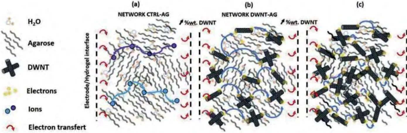
From these basic results, we propose a schematic representation for the charge transport in these complex nanocomposite hydro-gels (Fig. 7). The CTRL-AG sample (Fig. 5) appears to follow an ionic
conduction mechanism illustrated in Fig. 7a. The addition of
DWCNT seems to induce a Poole-Frenkel-like mechanism as illus-trated inFig. 7b. Indeed, the electric field applied to the terminals of the sample makes it possible to decrease the potential barrier of the traps distributed throughout the DWCNT-AG nanocomposite. This phenomenon allows electrons to jump from one position to another, increasing the electrical conduction steeply with the
in-crease in the electric field. The more DWCNT (Fig. 7c), the lower the
jumping distance. Indeed we suggest, as the number of DWCNT increases, that the distance between the DWCNT decreases. This illustration describes the proposed phenomena observed during the measurements.
4. Conclusion
The aim of this study was to determine the role played by DWCNT on the electrical properties of an Agarose/DWCNT nano-composite hydrogel. In our study, according to the impedance spectroscopy measurements, it appears that the percolation threshold is not reached, which seems unlikely, particularly for high loadings up to 40 wt % in the samples.
It remains unclear what is the impact of the water-induced expansion of the DWCNT network and its impact on the electrical percolation. Furthermore, continuous voltage measurements have demonstrated the effect of DWCNT in a nanocomposite hydrogel, different conduction phenomena can be observed at all studied concentrations of DWCNT, activated by the applied electric field. Complementary experiments are needed to determine whether the main conduction mechanism for DWCNT-AG is controlled by interfacial or bulk mechanisms.
From the above characteristics, the possibility remains open for using the CNT-based nanocomposite hydrogels for skin electro-stimulation. Nevertheless, it is necessary to better understand this nanomaterial under real conditions (with a drug solution inside, having its own electrical conductivity) in order to understand the material/tissue interaction for a biomedical application of such a device.
Acknowledgements
We would like to acknowledge support from the COMUE and
Midi-Pyrenees region (grant number 2014-110). Research was conducted in the scope of the EBAM European Associated Labora-tory (LEA). We thank the EU funded COST action TD1104. We would like to thank Dr Justin Teissie and Dr Pierre-Louis Taberna for their help and helpful discussions. Finally, we also acknowledge financial
support by the CNRS D!efi Nano.
Appendix A. Supplementary data
Supplementary data to this article can be found online at
https://doi.org/10.1016/j.carbon.2019.01.090. References
[1] P.M. Ajayan, O. Stephan, C. Colliex, D. Trauth, Aligned carbon nanotube Arrays formed by cutting a polymer resin - nanotube composite, Science 265 (5176) (1994) 1212e1214.
[2] Z. Han, A. Fina, Thermal conductivity of carbon nanotubes and their polymer nanocomposites: a review, Prog. Polym. Sci. 36 (2011) 914e944.
[3] S. Barrau, P. Demont, A. Peigney, C. Laurent, C. Lacabanne, DC and AC con-ductivity of carbon nanotubes-polyepoxy composites, Macromolecules 36 (2003) 5187e5194.
[4] E.T. Thostenson, C. Li, T.W. Chou, Nanocomposites in context, Compos. Sci. Technol. 65 (2005) 491e516. Polymer Nanotube Nanocomposites, Synthesis, Properties,and Applications, Edited by Vikas M., Scrivener Publishing LLC and John Wiley & Sons, Inc., Hoboken, New Jersey, Massachusetts. ISBN 978-0-470-62592-7, (2010), 460 pages.
[5] W. Bauhofer, J.Z. Kovacs, A review and analysis of electrical percolation in carbon nanotube polymer composites, Compos. Sci. Technol. 69 (2009) 1486e1498.
[6] E. Flahaut, M.C. Durrieu, M. Remy-Zolghadri, R. Bareille, C. Baquey, Investi-gation of the cytotoxicity of CCVD carbon nanotubes towards human umbilical vein endothelial cells, Carbon 44 (2006) 1093e1099.
[7] A. B!eduer, F. Seichepine, E. Flahaut, I. Loubinoux, L. Vaysse, C. Vieu, Elucidation of the role of carbon nanotube patterns on the development of cultured neuronal cells, Langmuir 28 (2012) 17363e17371.
[8] K. Kawaguchi, M. Fukushima, T. Hayakawa, T. Nakashima, N. Inoue, Y. Takeda, S. Taniguchi, Preparation of carbon nanotube-alginate nanocomposite gel for tissue engineering, Dent. Mater. J. 25 (2006) 719e725.
[9] K. Servant, A. Leon, V. Jasim, D. Methven, L. Limousin, E.V. Fernandez-Pacheco, M. Prato, K. Kostarelos, Graphene-based electroresponsive scaffolds as poly-meric implants for on-demand drug delivery, Adv. Healthc. Mater. 3 (8) (2014) 1334e1343.
[10] P. Schexnailder, G. Schmidt, Nanocomposite polymer hydrogels, Colloid Polym. Sci. 287 (2009) 1e11.
[11] A.K. Gaharwar, N.A. Peppas, A. Khademhosseini, Nanocomposite hydrogels for biomedical applications, Biotechnol. Bioeng. 111 (2014) 441e453. [12] N.S. Satarkar, D. Biswal, J.Z. Hilt, Hydrogel nanocomposites: a review of
ap-plications as remote controlled biomaterials, Soft Matter 6 (2010) 2364. [13] S. Goenka, V. Sant, S. Sant, Graphene-based nanomaterials for drug delivery
and tissue engineering, J. Contr. Release 173 (2014) 75e88.
[14] A. Servant, L. Methven, R.P. Williams, K. Kostarelos, Electroresponsive polymer-carbon nanotube hydrogel hybrids for pulsatile drug delivery in vivo, Adv. Healthc. Mater. 2 (2013) 806e811.
Fig. 7. Illustration showing the different possible conduction mechanisms for different samples. a) CTRL-AG illustrating an ionic conduction mechanism. b, c) DWCNT-AG illustrating a Poole-Frenkel type conduction mechanism. Red arrows indicate electron transfers at the opposite hydrogel contact interfaces. (A colour version of this figure can be viewed online.)
[15] M. Sasaki, B.C. Karikkineth, Nagamine, H. Kaji, K. Torimitsu, M. Nishizawa, Highly conductive stretchable and biocompatible electrode-hydrogel hybrids for advanced tissue engineering, Adv. Healthc. Mater. 3 (2014) 1919e1927. [16] N. Hur, J. Im, K. Kim, S.W. Kim, J. Chung, D.Y. Kim, T.H. Park, Polypyrrole/
agarose-based electronically conductive and reversibly restorable hydrogel, ACS Nano (2014) 810066e810076.
[17] S.R. Shin, S.M. Jung, M. Zalabany, K. Kim, P. Zorlutuna, S. bok Kim, M. Nikkhah, Khabiry, M. Azize, J. Kong, K.T. Wan, T. Palacios, M.R. Dokmeci, H. Bae, X. Tang, A. Khademhosseini, Carbon-nanotube-embedded hydrogel sheets for engi-neering cardiac constructs and bioactuators, ACS Nano 7 (2013) 2369e2380. [18] S. S. Naficy, J.M. J.M. Razal, G.M. Spinks, G.G. Wallace, P.G. Whitten, Electrically conductive, tough hydrogels with pH sensitivity, Chem. Mater. 24 (2012) 3425e3433.
[19] M. Chen, L. Zhang, S. Duan, S. Jing, H. Jiang, C. Li, Highly stretchable conductors integrated with a conductive carbon nanotube/graphene network and 3D porous poly (dimethylsiloxane), Adv. Funct. Mater. 24 (2014) 7548e7556. [20] H. Warren, R.D. Gately, P. O'Brien, R. Gorkin, M. In Het Panhuis, Electrical
conductivity, impedance, and percolation behavior of carbon nanofiber and carbon nanotube containing gellan gum hydrogels, J. Polym. Sci., Part B: Polym. Phys. 52 (2014) 864e871.
[21] R. Vanbever, U.F. Pliquett, V. Pr!eat, J.C. Weaver, Comparison of the effects of short, high-voltage and long, medium-voltage pulses on skin electrical and transport properties, J. Contr. Release 60 (1999) 35e47.
[22] R. Pomfret, K. Sillay, G. Miranpuri, Investigation of the electrical properties of agarose gel: characterization of concentration using nyquist plot phase angle and the implications of a more comprehensive in vitro model of the brain, Ann. Neurosci. 20 (2013) 99e107.
[23] A. Islam, Z. Imran, T. Yasin, N. Gull, S.M. Khan, M. Shafiq, A. Sabir, M.A. Munawar, M.H. Raza, T. Jamil, An investigation of ac impedance and dielectric spectroscopic properties of conducting chitosan-silane crosslinked-poly (Vinyl Alcohol) blended films, Mater. Res. 18 (2015) 1256e1263. [24] J. Shang, Z. Shao, X. Chen, Electrical behavior of a natural polyelectrolyte
hydrogel: chitosan/carboxymethylcellulose hydrogel, Biomacromolecules 9 (2008) 1208e1213.
[25] F.A. Aouada, M.R. Guilherme, G.M. Campese, E.M. Girotto, A.F. Rubira, E.C. Muniz, Electrochemical and mechanical properties of hydrogels based on conductive poly(3,4-ethylene dioxythiophene)/poly(styrenesulfonate) and PAAm, Polym. Test. 25 (2006) 158e165.
[26] T. Dai, X. Qing, H. Zhou, C. Shen, J. Wang, Y. Lu, Mechanically strong con-ducting hydrogels with special double-network structure, Synth. Met. 160 (2010) 791e796.
[27] M.A. N!eouze, J. Le Bideau, P. Gaveau, S. Bellayer, A. Vioux, Ionogels. new materials arising from the confinement of ionic liquids within silica-derived networks, Chem. Mater. 18 (2006) 3931e3936.
[28] Kishi R,.Hiroki K, Tominaga T, Sano KI, Okuzaki H, Martinez JG., Otero TF, Osada Y. Electro-conductive double-network hydrogels. J. Polym. Sci., Part B: Polym. Phys. ;50:790e796.
[29] L.Y. Yan, H. Chen, P. Li, D.H. Kim, M.B. Chan-Park, Finely dispersed single-walled carbon nanotubes for polysaccharide hydrogels, ACS Appl. Mater. In-terfaces 4 (2012) 4610e4615.
[30] J.F. Guillet, E. Flahaut, M. Golzio, A hydrogel/carbon-nanotube needle-free device for electrostimulated skin drug delivery, ChemPhysChem 18 (2017) 2715e2723.
[31] E. Flahaut, R. Bacsa, A. Peigney, Ch Laurent, Gram-scale CCVD synthesis of double-walled carbon nanotubes, Chem. Commun. 12 (2003) 1442e1443. [32] R. K€otz, M. Carlen, Principles and applications of electrochemical capacitors,
Electrochim. Acta 45 (2000) 2483e2498.
[33] A. Albina, P.-L. Taberna, J.-P. Cambronne, P. Simon, Flahaut, T. Lebey, Influence of carbonaceous electrodes on capacitance and breakdown voltage for hybrid capacitor, Microelectron. J. 38 (2007) 642e648.
[34] G. Sawa, S. Nakamura, K. Iida, M. Ieda, Electrical conduction of poly-pyromellitimide films at temperatures of 120-180#C, Jpn. J. Appl. Phys. 19 (3) (1980) 453e458.
[35] S.M. Sze, K.K. Ng, Physics of Semiconductor Devices, third ed., Wiley-inter-science, 2007.
[36] K. Rajavel, S. Verma, K. Asokan, R.R. Kumar, Field and temperature dependent electron transport properties of random network single walled and multi walled carbon nanotubes, Mater. Res. Express (2014) 035004.