HAL Id: hal-02132950
https://hal.archives-ouvertes.fr/hal-02132950
Submitted on 8 Dec 2020
HAL is a multi-disciplinary open access
archive for the deposit and dissemination of
sci-entific research documents, whether they are
pub-lished or not. The documents may come from
teaching and research institutions in France or
abroad, or from public or private research centers.
L’archive ouverte pluridisciplinaire HAL, est
destinée au dépôt et à la diffusion de documents
scientifiques de niveau recherche, publiés ou non,
émanant des établissements d’enseignement et de
recherche français ou étrangers, des laboratoires
publics ou privés.
Microfibers for Hydrogen Evolution Electrocatalysis
Jordi Creus, Laura Mallón, Nuria Romero, Roger Bofill, Alicia Moya, Jose
Fierro, Rubén Mas-Ballesté, Xavier Sala, Karine Philippot, Jordi
García-Antón
To cite this version:
Jordi Creus, Laura Mallón, Nuria Romero, Roger Bofill, Alicia Moya, et al.. Ruthenium Nanoparticles
Supported on Carbon Microfibers for Hydrogen Evolution Electrocatalysis. European Journal of
Inorganic Chemistry, Wiley-VCH Verlag, 2019, 2019 (15), pp.2071-2077. �10.1002/ejic.201801438�.
�hal-02132950�
Ruthenium Nanoparticles Supported on Carbon Microfibers for Hydrogen
Evolution Electrocatalysis
Jordi Creus
[a,b,c], Laura Mallón
[a,b,c], Nuria Romero
[a], Roger Bofill
[a], Alicia Moya
[d], Jose L. G. Fierro
[e],
Rubén Mas-Ballesté*
[d,f], Xavier Sala
[a], Karine Philippot*
[b,c], Jordi García-Antón*
[a]Abstract: Four different cathodes for the hydrogen evolution reaction (HER) have been developed by the decoration of commercial carbon microfibers with Ru nanoparticles (Ru NPs). Two types of carbon fibers have been used: pristine, as-received, carbon fibers (pCF) and carbon fibers modified by an oxidative treatment that led to the functionalization of their surface with carboxylic groups (fCF). The decoration of these CFs with Ru NPs has been performed by two different methodologies based on the organometallic approach: direct synthesis of Ru NPs on top of the CFs (in-situ Ru NPs) or impregnation of the CFs with a colloidal solution of preformed Ru NPs stabilized with 4-phenylpyridine (RuPP NPs; ex-situ Ru NPs). The electrocatalytic performance of these four cathodes (ex-situ RuPP@pCF and RuPP@fCF; in-situ Ru@pCF and Ru@fCF) for the HER has been studied in acidic conditions. The results obtained show that both the nature of the NPs and of the carbon fibers play a key role on the stability and activity of the hybrid electrodes: ex-situ prepared Ru NPs afford better activities at lower overpotentials and better stabilities than those formed in-situ. Among the two ex-situ systems, an enhancement of the stability with pCF is observed, that may arise from more effective π-interactions between 4-phenylpyridine ligand and the surface of these carbon fibers. This interaction is somehow disfavoured with fCF due to the presence of the surface carboxylic groups.
Introduction
During the last decades, the world energy demand has significantly increased, 1 meaning that there is a huge
requirement of energy sources to fulfil this necessity. Additionally, the abusive use of fossil fuels, which are actually running out, has been damaging the atmosphere and ozone layer, leading to environmental and health issues.2 Thus, an alternative to
carbon-based fuels needs to be found, which must be clean and
renewable. Hydrogen has been thoroughly studied as an energy vector due to its interesting properties as energy carrier3 and the
cleanness of its consumption. Although nowadays the main production process is the steam reforming from natural gas, water splitting (WS) has proved to be a promising renewable method for the formation of H2 through the Hydrogen Evolution
Reaction (HER) and the redox counterpart Oxygen Evolution Reaction (OER).4
The evolution of H2 from water through the reduction of protons
is achieved mainly with Pt-based catalysts, which are considered the state-of-the-art catalysts for this reaction. This relies in the fact that the Pt-H bond is strong enough to be stable but still weak enough to be easily broken and facilitate H2 formation.5
The scarcity and high cost of Pt, as well as its low stability in alkaline media,5b encourages the scientific community to
investigate other metals.6 In acidic media, first-row transition
metals show low stability, presumably due to acid corrosion, and their overpotentials under basic conditions are far to be competitive with those of Pt. 7 In contrast, Ru seems an ideal
candidate because i) the Ru-H bond energy is slightly weaker than the Pt-H one, what has no significant influence on the overpotentials in comparison to Pt-based catalysts, and ii) it presents high stability both at acidic and basic pH.5 Additionally,
its price is only 1/4th of that of Pt, thus increasing the HER
cost-efficiency of Ru-based species.
The use of NPs as (electro)catalysts for the HER has been gathering more and more attention in the last years. This interest arises from the particular properties of NPs that combine features from both homogeneous and heterogeneous systems. This includes a higher stability compared to molecular complexes and intrinsically high surface/volume ratio.8 In
contrast, electron transfer in NP-based electrocatalysts is typically not as good as it can be with molecular complexes, being that solved with the immobilization onto solid supports and electrodes, as e.g. highly-conductive carbon-based materials,9
silica,10 oxides,11 or even directly onto glassy carbon (GC)
electrodes.12
NPs size, shape, structure and homogeneity are crucial characteristics affecting the performance of nanosized catalytic systems. A good control on the surface environment and NPs structure is required in the methodology used for the synthesis to correlate the physical/chemical properties of the system and the catalytic output, and hence for the future rational design of new active and stable nanometric materials. In this sense, and as a result of the method used for their synthesis and stabilization, we have recently reported two different nanomaterials displaying interesting activities in the electrocatalytic HER.13,14 This method,
the so-called organometallic approach, permits to have very small NPs of controlled dimension and narrow size-distribution, applying mild synthetic reaction conditions and avoiding the use of salts, thus controlling their surface environment and their [a] Departament de Química, Universitat Autònoma de Barcelona,
Cerdanyola del Vallès, 08193 Barcelona, Spain. Email: [email protected]
https://seloxcat.wordpress.com/
[b] LCC (Laboratoire de Chimie de Coordination), 205 Route de Narbonne, BP44099, 31077 Toulouse Cedex 4, France. Email: [email protected]
https://www.lcc-toulouse.fr/article117.html?lang=fr
[c] Université de Toulouse III, UPS, INPT, 31077 Toulouse Cedex 4, France.
[d] Department of Inorganic Chemistry (module 07), Facultad de Ciencias, Universidad Autónoma de Madrid, Madrid, Spain Email: [email protected]
[e] Instituto de Catálisis y Petroleoquímica, CSIC, Madrid, Spain [f] Institute for Advanced Research in Chemical Sciences (IAdChem),
Universidad Autónoma de Madrid, Madrid, Spain
Supporting information for this article is given via a link at the end of the document.
of the NPs catalytic performance and its relationship with their surface properties.
In a recent report,16 we studied carbon microfibers (CFs)
obtained from the pyrolysis of polyacrylonitrile (PAN).17 They
present a graphene-like structure including pyridyl moieties that can be easily oxidized to generate carboxylic acid groups in a limited extent. Such oxidative functionalization affords differentiated surface properties, i. e. nicotinic fragments as catalytic centres for the HER, but with maintained bulk electric
for Ru NPs allows the fabrication of stable and high surface area functionalized electrodes. In this work, carbon microfibers are used as supports of Ru-based NPs prepared either in-situ onto the CFs surface or ex-situ. The resulting hybrid materials are investigated in this work as cathodes in the HER. The obtained results demonstrate that the nature of the support (oxidized compared to bare CFs) as well as the pre-stabilization of the NPs (in-situ compared to ex-situ synthesized NPs) play a key role in the observed HER electroactivity, and more importantly, in the stability of the hybrid electrode materials synthesized.
Scheme 1. a) Schematic representation of the surface chemical composition of pristine carbon fibers (pCF; top left) and functionalized carbon fibers (fCF;
top-right) and experimental procedure for the deposition / synthesis of Ru NPs onto the surface of the carbon fibers. b) Schematic representation of the surface of the carbon fibers once the Ru NPs have been deposited / synthesized.
Results and Discussion
Synthesis and characterization.Four hybrid materials have been prepared for the study of their catalytic performance in the HER (Scheme 1). First, two different supports were used: pristine CFs (pCF) and functionalized CFs (fCF). Pristine CFs present a clean surface, as described previously;16 in contrast, fCF present carboxylic acid groups at
their surface as a result of the modification treatment of pCFs by
oxidation in a 1:1 mixture of H2SO4/H2O2. During this oxidation
process, the graphitic regions of the carbon fibers were not massively altered and, therefore, electric conductivity was preserved. These modified microfibers have been shown to be electroactive catalysts towards the HER16 thanks to the new
carboxylic acid moieties present (see Figures S1-S3 in the SI for TEM images of pCF and fCF, and their LSV curves before and after bulk electrolysis at η = 250 mV in a 1 M H2SO4 solution).
As shown in Scheme 1(a), pCF and fCF were decorated with Ru nanoparticles (Ru NPs) following two different methodologies, both based on the organometallic approach for the synthesis of
NPs.15 Thus, a certain amount of NPs can be loaded onto the
fibers surface, which can have different surface environments depending on the synthetic method used. The 1st methodology is
an in-situ synthesis. in which Ru NPs have been prepared by decomposing under hydrogen 10 mg of [Ru(cod)(cot)] (cod: 1,5-cyclooctadiene; cot: 1,3,5-cyclooctatriene) in the presence of the CFs (90 mg; THF, r.t., 3 bar H2). Both (pCF and fCF) were
placed at the same time in the reaction vessel to ensure the same reaction conditions, resulting in a final Ru/CF ratio of ≈ 0.6 wt.% for each case. By this way, naked metal atoms released from the decomposition of the Ru precursor nucleated directly onto the electrode surface (Scheme 1(b)). The NPs obtained under these conditions can only be stabilized by the different possible NP-CF(surface) interactions and with solvent molecules (THF). The 2nd methodology is an ex-situ approach. In this case,
the Ru particles (RuPP NPs) were pre-synthesized by decomposing [Ru(cod)(cot)] at r.t., under H2, in THF and in the
presence of 0.2 eq. of 4-phenylpyridine (PP) as stabilizer, as recently reported.14 The overnight soaking of xCF (x = p, f) into
the crude colloidal RuPP NPS dispersion led to the attachment of the NPs onto the CFs surface. The main difference with the 1st method is the presence of 4-phenylpyridine at the surface of
the Ru NPs when deposited onto the CF supports. As previously published,14 the RuPP NPs supported onto a glassy carbon disk
electrode have shown large current intensities at low overpotentials for the electrocatalytic HER, with excellent stability after 12-h of continuous catalysis both under strong acidic and basic conditions (1 M H2SO4 and 1 M NaOH,
respectively).
Figure 1. Representative TEM images of the hybrid materials a) Ru@pCF, b) Ru@fCF, c) RuPP@pCF and d) RuPP@fCF.
The combination of the two different supports and two synthetic methodologies allowed obtaining four different hybrid materials,
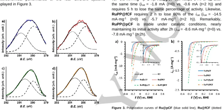
Ru@pCF, Ru@fCF, RuPP@pCF and RuPP@fCF, which have been characterized by TEM, XPS and ICP. The TEM analysis of these systems (Figure 1 and Figures S4-S7) confirmed in all cases the presence of very small particles onto the surface of the CFs. Even if some agglomerates constituted of very small NPs can be observed in a few zones of the microfibers, the Ru NPs mostly form a homogeneous layer at their surface, except for the Ru@fCF system, for which NPs agglomeration has been repeatedly observed. This parameter could be significant when testing the electrocatalytic performance of this particular system. Given the difficulty to take images of NPs of less than 2 nm on top of CFs of 8 µm of diameter, the mean size of the Ru NPs was difficult to measure and was estimated to be comprised within the 1.0-1.8 nm range for the four cases (see Table 1). XPS analyses (Figure 2) show that the Ru NPs contain two phases, metallic Ru and RuO2, due to a partial oxidation of the
surface of the NPs when exposed to air, with Ru 3d5/2 peaks
centred at 279.8 eV (metallic Ru) and 280.8 eV (RuO2).18 ICP
data of the whole material slightly varies from one sample to another, being the Ru content lower than 2% in all cases, as expected if we take into account the relative thickness of the fibers compared to those of the NPs, thus implying a high C content (Table 1).
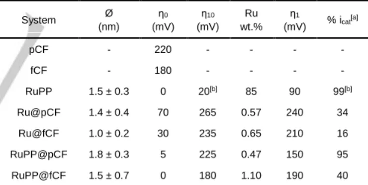
Table 1. Mean size and electrochemical HER performance of Ru@pCF,
Ru@fCF, RuPP@pCF and RuPP@fCF in 1 M H2SO4 aqueous solution. Ø = mean size of the Ru NPs; η0 = onset overpotential; η10 = overpotential at |icat| = 10 mA·mg-1; Ru wt. % = weight percentage of Ru in the sample, η
1 =
overpotential at |iRu|= 1 A·mg-1, % icat = percentage of current intensity at η = 200 mV after a 2 h electrolysis. System Ø (nm) η0 (mV) η10 (mV) Ru wt.% η1 (mV) % icat [a] pCF - 220 - - - - fCF - 180 - - - - RuPP 1.5 ± 0.3 0 20[b] 85 90 99[b] Ru@pCF 1.4 ± 0.4 70 265 0.57 240 34 Ru@fCF 1.0 ± 0.2 30 235 0.65 210 16 RuPP@pCF 1.8 ± 0.3 5 225 0.47 150 95 RuPP@fCF 1.5 ± 0.7 0 180 1.10 190 40 [a] %icat calculated by dividing icat (η = 200 mV) at t = 2 h by the value at t = 0 as short-term stability data. [b] Data for RuPP is taken from reference 14 for |j|= 10 mA·cm-2 instead of |i
cat |= 10 mA·mg-1.
Electrocatalytic HER performance.
For the electrocatalysis experiments, the electrodes were built with 1 mg of each hybrid material to avoid reproducibility issues because of the aggregation of the microfibers when used in higher amounts, as well as to minimize the effect of accumulation of H2 bubbles, since the gas is produced as big
bubbles that block the electrode surface and diminish its electrochemical response. For further details on the electrode preparation, see the Experimental Section. The electrodes were tested under reductive potentials in a two-compartment cell containing 1 M H2SO4. First, a change on the current intensity
thermodynamic potential for the HER (Etherm). The current
intensity, which is referenced per mg of material as icat =
[mA·mgcat-1], has been also normalized by the Ru wt.% in each
case in order to be able to compare the catalytic activity between samples with different Ru loadings, and the new values were labelled as iRu = [A·mgRu-1]. Table 1 summarizes the
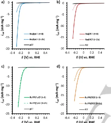
electrochemical performance of the four different systems displayed in Figure 3.
Figure 2. XPS analysis of a) Ru@pCF (blue, left), b) Ru@fCF (red,
top-right), c) RuPP@pCF (green, left) and d) RuPP@fCF (orange, bottom-right). Metallic-Ru component (Ru 3d5/2-279.8 eV, dashed black), RuO2 -component (Ru 3d5/2-280.8 eV, dotted-black), envelope (bold).
First of all, the onset overpotential, η0, is close to 0 mV for
RuPP@pCF and RuPP@fCF, confirming a similar behaviour to that observed for RuPP NPs onto glassy carbon, as previously described (see RuPP-GC material in ref 14). This value is considerably lower than that observed for the CFs (catalytically inactive) and for the oxidized CFs (catalytically active). Thus, considering that similar values of η0 are observed using both
materials, we can conclude that, for RuPP@xCF electrodes, there is no influence of the carbon support in the catalytic activity of the generated hybrid materials, where the RuPP NPs work as catalytic centres independently of the support. In contrast, Ru@pCF and Ru@fCF show higher η0 (70 and 30 mV,
respectively) than RuPP@xCF, and comparable to the η0 values
reported in the literature for C-supported Ru NPs.9 From these
values, two main conclusions can be deduced. First, the presence of the 4-phenylpyridine ligand as stabilizer has a positive impact on the catalytic activity. Second, it seems that somehow there is a synergistic effect arising from the coexistence of Ru catalytic NPs and active organic fragments in Ru@fCF in comparison with Ru@pCF.
Stability studies were carried out through long term bulk electrolysis experiments with maintained |icat| ≈ 10 mA·mgcat-1 in
all cases. In the last column of Table 1, % icat (t = 2 h) values,
defined as the remaining current percentage measured by LSV at a specific overpotential (η = 200 mV) after 2 h of catalytic turnover, allow a comparison of the stability of the four systems (graphical data can be found in Figure 4). While Ru@fCF shows a decrease of its icat down to 16% in 2 h (icat = -5.0 mA·mg-1 (t=0)
vs. -0.8 mA·mg-1 (t=2 h), Ru@pCF still keeps 34% of i cat after
the same time (icat = -1.8 mA (t=0) vs. -0.6 mA (t=2 h)) and
requires 5 h to lose the same percentage of activity. Likewise, RuPP@fCF requires 2 h to lose 60% of the icat (icat = -14.5
mA·mg-1 (t=0) vs. -5.7 mA·mg-1 (t=2 h)). Remarkably,
RuPP@pCF is stable under catalytic conditions, nearly maintaining its initial activity after 2h (icat = -8.6 mA·mg-1 (t=0) vs.
-7.8 mA·mg-1 (t=2h).
Figure 3. Polarization curves of Ru@pCF (blue solid line), Ru@fCF (dotted
red line), RuPP@pCF (dashed green line), RuPP@fCF (dash-dotted orange line), pCF (black solid line) and fCF (grey solid line) normalized by mg of material (a) and by mg of Ru (b). The 1-mg working electrodes were prepared as described in the Experimental Section. A Pt mesh and a Ag/AgCl (KCl sat.) electrodes were used as counter (CE) and reference electrodes (RE), respectively. The threeelectrode configuration was polarized from 0.6 V to -0.25 V (vs. RHE) at a scan rate of 10 mV·s-1.
To unravel the causes influencing the stability of the four systems, TEM analyses of the electrode materials after the 2h bulk electrolysis experiments were performed. Comparing TEM images (Figures S8-S11), there is visual evidence that the in-situ prepared Ru@xCFs systems suffer significant leaching during the catalytic process, leaving cleaner surfaces of the CFs for both Ru@pCF and Ru@fCF (Figures S8 and S9, respectively), but that nevertheless also contain some agglomerates, which have been formed during the catalytic reaction. This trend is confirmed by the EDX analysis of the surface of Ru@pCF and Ru@fCF (Figures S8 and S9, respectively), showing almost no presence of Ru, in agreement with the electrocatalytic results. In contrast, the two RuPP-based systems (RuPP@pCF and RuPP@fCF) present higher loadings of Ru NPs on the surface of the fibers after catalysis (Figures S10 and S11, respectively) than the Ru@xCF systems, with very small NPs along the CFs surface and almost no agglomeration observed. EDX analyses (Figures S10 and S11, respectively) confirm, in this case, the presence of Ru throughout the surface. In our previous publication,14 RuPP NPs deposited onto a GC electrode with no
gluing agent added were held at a constant current density of j = −10 mA·cm−2 in a 12 h current-controlled experiment in the
same acidic conditions as in the present work (1 M H2SO4).
Moreover, RuPP NPs presented no deactivation signs, and displayed identical LSV polarization curves before and after the catalytic turnover. Considering these previous results, it is clear that RuPP NPs are stable under the applied catalytic conditions. Consequently, the deactivation observed for RuPP@fCF can be
attributed to a mechanical instability of the NPs. Thus, there may occur a continuous loss of NPs from the surface of the CFs, which may settle down at the bottom of the reaction vessel as detached NPs.
Figure 4. LSV curves for a) Ru@pCF, b) Ru@fCF, c) RuPP@pCF and d) RuPP@fCF recorded along a bulk electrolysis experiment in 1 M H2SO4 to study the stability of the different systems. An Eapp= -250 mV was used for the Ru@xCF systems to reach icat ≈ 10 mA·mg-1 during the electrolysis, while an Eapp= -150 mV was used for the RuPP-based systems. The 1-mg working electrodes were prepared as described in the Experimental Section. A Pt mesh and a Ag/AgCl (KCl sat.) electrodes were used as counter (CE) and reference electrodes (RE), respectively. The three-electrode configuration was polarized from 0.6 V to -0.25 V (vs. RHE) at a scan rate of 10 mV·s-1.
Further mechanistic information has been obtained from the Tafel plots of the four hybrid materials, Ru@pCF, Ru@fCF, RuPP@pCF and RuPP@fCF (Figure S12). Tafel slope values in the 82-212 mv·dec-1 range point to the Volmer step as rds of the
HER process.
Faradaic efficiency (FE, %) of the hybrid materials has been evaluated by performing 10-min bulk electrolysis experiments with an H2-Clark sensor which allows the in-situ detection of the
generated H2. The charge passed through the system was
transformed first to moles of electrons by the Faradaic constant,
and then to theoretical H2 moles by taking into account that the
formation of hydrogen gas requires two electrons per molecule. The experimental data for H2 generation were extracted from the
Clark sensor calibrating the electrochemical signal (mV) with different amounts of 99% pure H2 and extrapolating the obtained
data. The FE was estimated by dividing the value detected by the H2-Clark sensor by the charge value at the end of the
experiment, confirming that almost quantitative number of electrons were specifically devoted to the reduction of protons and not to other side processes (see Figure S13).
Altogether, the electrocatalytic results evidence that both the nature of the carbonaceous fibers and the surface environment of the NPs play a key role on the activity and stability of the hybrid materials used as cathodes in the HER. Considering the activity of the hybrid materials, ex-situ RuPP-systems (RuPP@pCF and RuPP@fCF) reach higher intensities at low overpotentials than the in-situ Ru-based ones (Ru@pCF and Ru@fCF). This behaviour confirms the positive effect of the interaction of the 4-phenylpyridine ligand with the NPs regarding their catalytic performance, as previously stated.14 If we take into
account the relative stabilities observed in the bulk electrolysis experiments, the ex-situ RuPP-systems (RuPP@pCF and RuPP@fCF) are more stable (95% and 40% activity maintained after 2-h, respectively) than the Ru-based ones (Ru@pCF and Ru@fCF; 34% and 16% activity maintained after 2-h, respectively). We propose that the improved stability of the RuPP-based hybrid materials derives from the properties of the 4-phenylpyridine ligand at the Ru NPs surface which, besides assuring the stabilization of the NPs, can also favour their anchoring at the surface of the support, probably through π-stacking interactions with the surface of the CFs. If we only compare the RuPP-systems, the carboxylate groups in the RuPP@fCF electrode might hamper these π-stacking interactions, thus being detrimental for the mechanical stability of the Ru NPs at the surface of this particular C-based electrode.
Conclusions
Four different heterogeneous hybrid cathodes based on the decoration of CFs with Ru NPs have been designed and tested for the electrocatalytic HER. On the one hand, two types of CFs have been used: pristine (pCF) or functionalised (after an oxidative treatment that affords surface carboxylic groups; fCF) fibers. On the other hand, two types of Ru NPs prepared through the organometallic synthesis method have been loaded onto the surface of the CFs: Ru NPs prepared in-situ on top of the CFs or Ru NPs synthesized ex-situ with 4-phenylpyridine (PP)14 and
subsequently deposited onto the surface of the CFs by an impregnation method. By this way, we had in hands two ex-situ (RuPP@pCF and RuPP@fCF) and two in-situ (Ru@pCF and Ru@fCF) cathodes for the electrocatalytic studies (Scheme 1). The electrochemical studies clearly indicate that the nature of the carbon fibers (pristine or carboxylic acid-functionalized) and the nature of the Ru NPs (in-situ or ex-situ) are decisive on the activity and stability of each of the four cathodes for the HER.
More specifically, both RuPP@xCF electrodes present η0
overpotentials close to 0 mV, similar to those obtained for RuPP NPs deposited onto a glassy carbon electrode. In this case, thanks to the outstanding electrocatalytic properties of the RuPP NPs, the nature of the carbon fibers is not decisive in the final output. On the other hand, the nature of the carbon fibers is indeed significant for the activity of Ru@xCF hybrid systems: Ru@fCF present a much lower η0 overpotential (30 mV) than
Ru@pCF (70 mV). This observation suggests that for Ru@fCF some degree of cooperation exists between the Ru NPs and the nicotinic moieties, which have been recently suggested as catalytic centres in non-decorated fCFs.16
Additionally, pCFs improve the stability of the cathodes, suggesting that the carboxylic groups onto the surface of the fCFs prevent the stabilization of the Ru NPs by the pyridyl-based structure of the CFs. If we consider the nature of the Ru NPs, RuPP-based cathodes (RuPP@xCF; x = p or f) present much higher stabilities and activities than those obtained with Ru NPs synthesized in-situ (Ru@xCF; x = p or f). These results confirm the positive effect of the 4-phenylpyridine capping ligand, not only acting as a stabilizing agent for the Ru NPs but also as a gluing agent of the nanocatalysts onto the C-based support, conferring mechanical stability to the hybrid cathode.
Overall, the results reported herein demonstrate the viability of hybrid materials composed by CFs and Ru NPs as remarkable electrocatalysts for the HER. The best compromise between activity and stability is achieved by using pristine CFs and Ru NPs stabilized by the surface coordination of 4-phenylpyridine. This is probably indicative of a better π-π interaction between the aromatic 4-phenylpyridine ligand and the graphitic region of the carbon fibers, which, in turn, can be hindered by the oxidative derivatization of the carbon material.
In conclusion, we designed electrodes with high surface area from a material with a low metal content (0.5% wt) on a macroscopic cheap substrate, allowing thus a step further towards the massive and economic production of hydrogen under benign conditions.
Experimental Section
Materials and reagents. All operations for the synthesis of the CF-supported Ru NPs were carried out using standard Schlenk tubes, Fisher–Porter bottle techniques or in a glove-box (MBraun) under argon atmosphere. Solvents (THF and pentane) were purified before use by filtration on adequate columns in a purification apparatus (MBraun) and handled under argon atmosphere. Solvents were degassed before use according to a freeze–pump–thaw process. The ruthenium precursor, [Ru(cod)(cot)], was purchased from Nanomeps-Toulouse. Hydrogen gas (Alphagaz) was purchased from Air Liquide. 4-Phenylpyridine used as stabilizer was purchased from Sigma-Aldrich and used as received. High purity deionized water was obtained by passing distilled water through a nanopore Milli-Q water purification system. Pristine carbon fibers were purchased from ClipCarbono19.
CF electrode preparation. Carbon fibers were washed by sonication for 10–15 min in isopropanol and dried with a heat gun. The fCF material was prepared by exposing the pCF ready‐made electrodes to commercial sulfuric acid (98 %) at r.t. during 30 min under stirring. Then,
the material was placed into a H2SO4/H2O2 1:1 mixture. The H2O2 was
fresh and the mixture with H2SO4 was prepared a few minutes before use.
The electrodes were washed and sonicated in distilled water to remove all acid traces among fibers; this required several washing cycles. When the pH of the water was constant, the electrodes were sonicated for 10– 15 min in isopropanol and dried with a heat gun. The carbon fiber electrodes were hand-made prepared using a short copper wire, ≈50 cm long carbon fibers and some Teflon tape to tight everything together. The CFs electrodes contain 7 bundles of 3000 filaments (21000 filaments) of 8 µm diameter and 6 cm length each. The fibers were bended so each electrode contained the double of the filaments (42000). Only 2 cm were exposed for the synthesis of the NPs and electrode usage. These electrodes weighted approximately 90 mg. After deposition of the NPs but before electrochemical evaluation, these electrodes were cut in 3-cm-long filaments (half fiber), and 1-mg-samples were attached to a Cu tape together with a Cu-wire, still ensuring 2 cm were left for catalysis evaluation.
Ru@xCF, x = pristine (p) or functionalized (f). 2 cm of xCFs were soaked in a 10 mL THF solution containing [Ru(cod)(cot)] (10 mg, 0.026 mmol) inside a Fisher-Porter bottle. 3 bar of H2 were introduced and the
reaction mixture was stirred at r.t. overnight. After depressurization, the hydrogen was evacuated under vacuum and the solvent removed through a cannula. The resulting CF materials were rinsed with pentane and dried under vacuum. Ru@pCF. TEM: Ø = 1.4 ± 0.4 nm. ICP(Ru%) = 0.57%. Ru@fCF. TEM: Ø = 1.0 ± 0.2 nm. ICP(Ru%) = 0.65%.
RuPP@xCF, x = pristine (p) or functionalized (f). 2 cm of xCFs electrodes were soaked overnight in a THF (10 mL) crude dispersion of RuPP NPs14 inside a Fisher-Porter bottle. Then, the supernatant was
removed through cannula and the resulting CF materials were rinsed with pentane (3x10 mL) and dried under vacuum. RuPP@pCF. TEM: Ø = 1.8 ± 0.3 nm. ICP(Ru%): 0.47%. RuPP@fCF. TEM: Ø = 1.5 ± 0.7 nm. ICP (Ru%): Ru@fCF: 1.10%.
Characterization
Transmission Electron Microscopy (TEM) and High-Resolution Electron Microscopy (HREM). TEM and HREM observations were performed at the “Centre de Microcaractérisation Raymond Castaing” in Toulouse (UMS-CNRS 3623) and at the “Servei de Microscòpia Electrònica” of the UAB. Samples for TEM and HREM analyses were prepared by deposition of several CFs onto a holey carbon-covered copper grid. TEM and HREM analyses were performed on a MET JEOL JEM 1011 microscope operating at 100 kV with a resolution point of 0.45 nm and a JEOL JEM-ARM 200F microscope working at 200 kV with a resolution point lower of 0.19 nm, respectively. TEM allowed to evaluate the particle size, size distribution and morphology. Enlarged micrographs were used for treatment with ImageJ software to obtain a statistical size distribution and the NP mean diameter. The analyses were done by assuming that the NPs were spherical. NP sizes are quoted as the mean diameter ± the standard deviation.
Inductive-Coupled Plasma (ICP-OES). ICP-OES measurements were performed at the “Servei d’Anàlisis Químic” (SAQ) in the UAB, on an Optima 4300DV Perkin-Elmer system. Solid samples were prepared by digesting 1 mg of the hybrid CFs with aqua regia under microwave conditions followed by a dilution of the mixture with HCl 1% (v/v). Liquid samples were directly diluted with HCl 1% (v/v).
X-Ray Photoelectron Spectroscopy (XPS). Measurements were performed at the Catalan Institute of Nanoscience and Nanotechnology (ICN2) in Barcelona with a Phoibos 150 analyzer (SPECS GmbH, Berlin,
Germany) in ultra-high vacuum conditions (base pressure 5·10-10 mbar)
with a monochromatic aluminium Kalpha x-ray source (1486.74 eV). The energy resolution was measured by the FWHM of the Ag 3d5/2 peak
which for a sputtered silver foil was 0.62 eV.
Electrochemical measurements. All the electrochemical experiments were performed using a BioLogic SP-150 potentiostat. Solutions were degassed before the electrochemical analysis with a N2 flow. IR drop was
automatically corrected at 85 % using the Biologic EC-Lab software for cyclic voltammetry and chronoamperometry. 1 M H2SO4 solution was
prepared by mixing 56.1 mL of 95-97 % H2SO4 in 1 L of Mili-Q water. A
Pt grid was used as a counter electrode (CE) and an Ag/AgCl (KCl sat.) electrode was used as a reference electrode (RE). All data were transformed to RHE by adding +0.20 V. A 10 mL two-compartment cell with a separation membrane between the two compartments was used. Both compartments were filled with 8 mL of 1 M H2SO4 solution and were
equipped with a stirring bar. Prior to each measurement, they were purged with N2 for 15 min. For H2-monitored bulk electrolysis an
Unisense H2-NP Clark electrode was used to measure hydrogen evolution in the gas phase and to calculate the Faradaic efficiency. The Clark electrode was calibrated by adding different volumes of 99% pure hydrogen at the end of the experiment. The CE was placed in one compartment and the other was provided with the WE, the RE and the Clark electrode.
Linear Sweep Voltammetry (LSV). The system was scanned from Ei =
0.6 V to Ef = -0.4 V at 10 mV/s scan rate unless otherwise stated.
Chronoamperometry. Controlled potential chronoamperometric experiments were performed at Eapp = -0.25 V and -0.15 V for Ru- and
RuPP-CF based systems, respectively.
Acknowledgments
This work was financially supported by the MINECO/FEDER project CTQ2015-64261-R and CTQ2015-64561-R, the CNRS, the Univ. Toulouse III - Paul Sabatier and the GDRI HC3A Franco-Catalan action. J.C. thanks the UAB and the “Euroregió Pirineus Mediterrànea” for PhD grants. J.G.-A. acknowledges the Serra Húnter Program. The authors acknowledge Guillaume Sauthier for XPS analysis.
Keywords: carbon fibers · energy conversion · hydrogen evolution reaction ·nanoparticles · ruthenium
[1] BP Energy Outlook 2018, BP Global.
[2] V. Scott, R. S. Haszeldine, S. F. B. Tett, A. Oschlies, Nat. Clim. Change
2015, 5, 419-423.
[3] N. S. Lewis, Nature 2001, 414, 589-590.
[4] S. Berardi, S. Drouet, L. Francàs, C. Gimbert-Suriñach, M. Guttentag, C. Richmond, T. Stoll, A. Llobet, Chem. Soc. Rev. 2014, 43, 7501-7519. [5] a) S. Trasatti, J. Electroanal. Chem. 1972, 39, 163-184; b) C. C. L.
McCrory, S. Jung, I. M. Ferrer, S. M. Chatman, J. C. Peters, T. F. Jaramillo, J. Am. Chem. Soc. 2015, 137, 4347-4357; c) J. K. Norskov, T.
Bligaard, A. Logadottir, J. R. Kitchin, J. G. Chen, S. Pandelov, U. Stimming, J. Electrochem. Soc. 2005, 152, J23-J26.
[6] a) N. Coutard, N. Kaeffer, V. Artero, Chem. Commun. 2016, 52, 13728-13748; b) A. Eftekhari, Int. J. Hydrogen Energy 2017, 42, 11053-11077. [7] a) Y. G. Li, H. L. Wang, L. M. Xie, Y. Y. Liang, G. S. Hong, H. J. Dai,
Am. Chem. Soc. 2011, 133, 7296-7299; b) E. J. Popczun, J. R.
McKone, C.G. Read, A. J. Biacchi, A. M. Wiltrout, N. S. Lewis, R. E. Schaak, J. Am. Chem. Soc. 2013, 135, 9267-9270; c) T. F. Jaramillo, K. P. Jorgensen, J. Bonde, J. H. Nielsen, S. Horch, I. Chorkendorff,
Science 2007, 317, 100−102; d) J. R. McKone, B. F. Sadtler, C. A. Werlang, N. S. Lewis, H. B. Gray, ACS Catal. 2013, 3, 166-169; e) L. Liao, S. N. Wang, J. J. Xiao, X. J. Bian, Y. H. Zhang, M. D. Scanlon, X. L. Hu, Y. Tang, B. H. Liu, H. H. Girault, Energy Environ. Sci. 2014, 7, 387-392.
[8] M. Zheng, Y. Li, J. Mater. Chem. A 2015, 3, 14942-14962.
[9] a) J. Mahmood, F. Li, S. Jung, M. S. Okyay, I. Ahmad, S. Kim, N. Park, H. Y. Jeong, J. Baek, Nature Nanotech. 2017, 12, 441-446; b) T. Bhowmik, M. K. Kundu, S. Barman, ACS Appl. Mater. Interfaces 2016,
8, 28678-28688; c) J. Cheng, H. Zhang, H. Ma, H. Zhong, Y. Zou, Electrchim. Acta 2010, 55, 1855-1861; d) X. Kong, K. Xu, C. Zhang, J.
Dai, S. N. Oliaee, L. Li, X. Zeng, C. Wu, Z. Peng, ACS Catal. 2016, 6, 1487-1492; e) Y. Zheng, Y. Jiao, Y. Zhu, L. H. Li, Y. Han, Y. Chen, M. Jaroniec, S. Qiao, J. Am. Chem. Soc. 2016, 138, 16174-16181; f) Z. Chen, J. Lu, Y. Ai, Y. Ji, T. Adschiri, L. Wan ACS Appl. Mater.
Interfaces 2016, 8, 35132-35137.
[10] a) Y. Zhang, T. Ren, Chem. Commun. 2012, 48, 11005-11007; b) N. C. King, C. Dickinson, W. Zhou, D. W. Bruce, Dalton Trans. 2005, 6, 1027-1032; c) K. P. J. Gustafson, A. Shatskiy, O. Verho, M. D. Kärkäs, B. Schluschass, C. Tai, B. Åkermark, J. Bäckvall, E. V. Johnston, Catal.
Sci. Technol. 2017, 7, 293-299.
[11] a) J. Liu, Y. Zheng, D. Zhu, A. Vasileff, T. Ling, S. Z. Qiao, Nanoscale
2017, 9, 16616-16621; b) P. Jiang, Y. Yang, R. Shi, G. Xia, J. Chen, J.
Su, Q. Chen, J. Mater. Chem. A 2017, 5, 5475-5485; c) U. Joshi, S. Malkhandi, Y. Ren, T. L. Tan, S. Y. Chiam, B. S. Yeo, ACS Appl. Mater.
Interfaces 2018, 10, 6354-6360; d) L. Zhu, Q. Cai, F. Liao, M. Sheng, B.
Wu, M. Shao, Electrochem. Commun. 2015, 52, 29-33; e) E. Demir, S. Akbayrak, A. M. Önal, S. Özkar, ACS Appl. Mater. Interfaces 2018, 10, 6299-6308.
[12] a) K. Magdić, K. Kvastek, V. Horvat-Radošević, Electrochim. Acta 2015,
167, 455-469; b) R. K. Shervedani, A. Amini, Carbon 2015, 93, 762-773.
[13] S. Drouet, J. Creus, V. Collière, C. Amiens, J. García-Antón, X. Sala, K. Philippot, Chem. Commun. 2017, 53, 11713-11716.
[14] J. Creus, S. Drouet, S. Suriñach, P. Lecante, V. Colliere, R. Poteau, K. Philippot, J. García-Antón, X. Sala, ACS Catal. 2018, 8, 11094-11102. [15] C. Amiens, B. Chaudret, D. Ciuculescu-Pradines, V. Collière, K.
Fajerwerg, P. Fau, M. Kahn, A. Maisonnat, K. Soulantica, K. Philippot,
New J. Chem. 2013, 37, 3374-3401.
[16] O. González-del Moral, A. Call, F. Franco, A. Moya, J. A. Nieto-Rodríguez, M. Frías, J. L. G. Fierro, M. Costas, J. Lloret-Fillol, J. Alemán, R. Mas-Ballesté, Chem. Eur. J. 2018, 24, 3305-3313. [17] a) Y. D. Liu and S. Kumar, Polym. Rev. 2012, 52, 234–258; b) X. S.
Huang, Materials 2009, 2, 2369-2403.
[18] D. M. Morgan, Surf. Interface Anal. 2015, 47, 1072-1079.
[19] Commercial carbon fiber, http://www.clipcarbono.com/es/home/266- tejido-de-fibra-de-carbono-sarga-2×2-3k-peso-200gr-m2-ancho-1200-mm.html.
Entry for the Table of Contents
FULL PAPER
Four heterogeneous hybrid cathodes for the catalytic hydrogen evolution reaction (HER) have been prepared combining two types of carbon fibers and two different synthetic
methodologies in order to decorate their surface with Ru nanoparticles. The activity and stability of all the hybrid systems have been evaluated.
Supported Nanoparticles Jordi Creus, Laura Mallón, Nuria Romero, Roger Bofill, Alicia Moya, Jose L. G. Fierro, Rubén Mas-Ballesté*, Xavier Sala, Karine Philippot*, Jordi García-Antón*
Page No. – Page No.
Ruthenium Nanoparticles Supported onto Carbon Microfibers for
1 BP Energy Outlook 2018, BP Global.
2 V. Scott, R. S. Haszeldine, S. F. B. Tett, A. Oschlies, Nat. Clim. Change 2015, 5, 419-423. 3 N. S. Lewis, Nature 2001, 414, 589-590.
4 S. Berardi, S. Drouet, L. Francàs, C. Gimbert-Suriñach, M. Guttentag, C. Richmond, T. Stoll, A. Llobet, Chem. Soc. Rev. 2014, 43,
7501-7519.
5 a) S. Trasatti, J. Electroanal. Chem. 1972, 39, 163-184; b) C. C. L. McCrory, S. Jung, I. M. Ferrer, S. M. Chatman, J. C. Peters, T. F.
Jaramillo, J. Am. Chem. Soc. 2015, 137, 4347-4357; c) J. K. Norskov, T. Bligaard, A. Logadottir, J. R. Kitchin, J. G. Chen, S. Pandelov, U. Stimming, J. Electrochem. Soc. 2005, 152, J23-J26.
6 a) N. Coutard, N. Kaeffer, V. Artero, Chem. Commun. 2016, 52, 13728-13748; b) A. Eftekhari, Int. J. Hydrogen Energy 2017, 42,
11053-11077.
7 a) Y. G. Li, H. L. Wang, L. M. Xie, Y. Y. Liang, G. S. Hong, H. J. Dai, Am. Chem. Soc. 2011, 133, 7296-7299; b) E. J. Popczun, J. R. McKone,
C.G. Read, A. J. Biacchi, A. M. Wiltrout, N. S. Lewis, R. E. Schaak, J. Am. Chem. Soc. 2013, 135, 9267-9270; c) T. F. Jaramillo, K. P. Jorgensen, J. Bonde, J. H. Nielsen, S. Horch, I. Chorkendorff, Science 2007, 317, 100−102; d) J. R. McKone, B. F. Sadtler, C. A. Werlang, N. S. Lewis, H. B. Gray, ACS Catal. 2013, 3, 166-169; e) L. Liao, S. N. Wang, J. J. Xiao, X. J. Bian, Y. H. Zhang, M. D. Scanlon, X. L. Hu, Y. Tang, B. H. Liu, H. H. Girault, Energy Environ. Sci. 2014, 7, 387-392.
8 M. Zheng, Y. Li, J. Mater. Chem. A 2015, 3, 14942-14962.
9 a) J. Mahmood, F. Li, S. Jung, M. S. Okyay, I. Ahmad, S. Kim, N. Park, H. Y. Jeong, J. Baek, Nature Nanotech. 2017, 12, 441-446; b) T.
Bhowmik, M. K. Kundu, S. Barman, ACS Appl. Mater. Interfaces 2016, 8, 28678-28688; c) J. Cheng, H. Zhang, H. Ma, H. Zhong, Y. Zou, Electrchim. Acta 2010, 55, 1855-1861; d) X. Kong, K. Xu, C. Zhang, J. Dai, S. N. Oliaee, L. Li, X. Zeng, C. Wu, Z. Peng, ACS Catal. 2016, 6, 1487-1492; e) Y. Zheng, Y. Jiao, Y. Zhu, L. H. Li, Y. Han, Y. Chen, M. Jaroniec, S. Qiao, J. Am. Chem. Soc. 2016, 138, 16174-16181; f) Z. Chen, J. Lu, Y. Ai, Y. Ji, T. Adschiri, L. Wan ACS Appl. Mater. Interfaces 2016, 8, 35132-35137.
10 a) Y. Zhang, T. Ren, Chem. Commun. 2012, 48, 11005-11007; b) N. C. King, C. Dickinson, W. Zhou, D. W. Bruce, Dalton Trans. 2005, 6,
1027-1032; c) K. P. J. Gustafson, A. Shatskiy, O. Verho, M. D. Kärkäs, B. Schluschass, C. Tai, B. Åkermark, J. Bäckvall, E. V. Johnston, Catal. Sci. Technol. 2017, 7, 293-299.
11 a) J. Liu, Y. Zheng, D. Zhu, A. Vasileff, T. Ling, S. Z. Qiao, Nanoscale 2017, 9, 16616-16621; b) P. Jiang, Y. Yang, R. Shi, G. Xia, J. Chen, J.
Su, Q. Chen, J. Mater. Chem. A 2017, 5, 5475-5485; c) U. Joshi, S. Malkhandi, Y. Ren, T. L. Tan, S. Y. Chiam, B. S. Yeo, ACS Appl. Mater. Interfaces 2018, 10, 6354-6360; d) L. Zhu, Q. Cai, F. Liao, M. Sheng, B. Wu, M. Shao, Electrochem. Commun. 2015, 52, 29-33; e) E. Demir, S. Akbayrak, A. M. Önal, S. Özkar, ACS Appl. Mater. Interfaces 2018, 10, 6299-6308.
12 a) K. Magdić, K. Kvastek, V. Horvat-Radošević, Electrochim. Acta 2015, 167, 455-469; b) R. K. Shervedani, A. Amini, Carbon 2015, 93,
762-773.
13 S. Drouet, J. Creus, V. Collière, C. Amiens, J. García-Antón, X. Sala, K. Philippot, Chem. Commun. 2017, 53, 11713-11716.
14 J. Creus, S. Drouet, S. Suriñach, P. Lecante, V. Colliere, R. Poteau, K. Philippot, J. García-Antón, X. Sala, ACS Catal. 2018, 8, 11094-11102. 15 C. Amiens, B. Chaudret, D. Ciuculescu-Pradines, V. Collière, K. Fajerwerg, P. Fau, M. Kahn, A. Maisonnat, K. Soulantica, K. Philippot,
New J. Chem. 2013, 37, 3374-3401.
16 O. González-del Moral, A. Call, F. Franco, A. Moya, J. A. Nieto-Rodríguez, M. Frías, J. L. G. Fierro, M. Costas, J. Lloret-Fillol, J. Alemán, R.
Mas-Ballesté, Chem. Eur. J. 2018, 24, 3305-3313.
17 a) Y. D. Liu and S. Kumar, Polym. Rev. 2012, 52, 234–258; b) X. S. Huang, Materials 2009, 2, 2369-2403. 18 D. M. Morgan, Surf. Interface Anal. 2015, 47, 1072-1079.
19