HAL Id: hal-01692704
https://hal.archives-ouvertes.fr/hal-01692704
Submitted on 25 Jan 2018
HAL is a multi-disciplinary open access
archive for the deposit and dissemination of
sci-entific research documents, whether they are
pub-lished or not. The documents may come from
teaching and research institutions in France or
abroad, or from public or private research centers.
L’archive ouverte pluridisciplinaire HAL, est
destinée au dépôt et à la diffusion de documents
scientifiques de niveau recherche, publiés ou non,
émanant des établissements d’enseignement et de
recherche français ou étrangers, des laboratoires
publics ou privés.
The Unexpected Complexity of Filling Double-Wall
Carbon Nanotubes With Nickel (and Iodine) 1-D
Nanocrystals
Chunyang Nie, Anne-Marie Galibert, Brigitte Soula, Lucien Datas, Jeremy
Sloan, Emmanuel Flahaut, Marc Monthioux
To cite this version:
Chunyang Nie, Anne-Marie Galibert, Brigitte Soula, Lucien Datas, Jeremy Sloan, et al.. The
Unex-pected Complexity of Filling Double-Wall Carbon Nanotubes With Nickel (and Iodine) 1-D
Nanocrys-tals. IEEE Transactions on Nanotechnology, Institute of Electrical and Electronics Engineers, 2017,
vol. 16 (n° 5), pp. 759-766. �10.1109/TNANO.2017.2686434�. �hal-01692704�
O
pen
A
rchive
T
OULOUSE
A
rchive
O
uverte (
OATAO
)
OATAO is an open access repository that collects the work of Toulouse researchers and
makes it freely available over the web where possible.
This is an author-deposited version published in :
http://oatao.univ-toulouse.fr/
Eprints ID : 19349
To link to this article : DOI:
10.1109/TNANO.2017.2686434
URL :
https://dx.doi.org/10.1109/TNANO.2017.2686434
To cite this version :
Nie, Chunyang and Galibert, Anne-Marie and Soula, Brigitte and
Datas, Lucien and Sloan, Jeremy and Flahaut, Emmanuel and
Monthioux, Marc The Unexpected Complexity of Filling
Double-Wall Carbon Nanotubes With Nickel (and Iodine) 1-D
Nanocrystals. (2017) IEEE Transactions on Nanotechnology, vol.
16 (n° 5). pp. 759-766. ISSN 1536-125X
Any correspondence concerning this service should be sent to the repository
administrator:
staff-oatao@listes-diff.inp-toulouse.fr
IEEE TRANSACTIONS ON NANOTECHNOLOGY, VOL. 16, NO. 5, SEPTEMBER 2017 759
The Unexpected Complexity of Filling Double-Wall
Carbon Nanotubes With Nickel (and Iodine)
1-D Nanocrystals
Chunyang Nie, Anne-Marie Galibert, Brigitte Soula, Lucien Datas, Jeremy Sloan, E. Flahaut, and Marc Monthioux
Abstract—A variety of iodine-based one-dimensional (1-D)
nanocrystals were introduced into double-wall carbon nanotubes (DWCNTs) using the molten phase method, as an intermediate step for ultimately obtaining encapsulated metal nanowires. Based on high-resolution transmission electron microscopy (HRTEM) ob-servations using different imaging modes (bright field, dark field, and scanning TEM) and associated analytical tools (electron energy loss spectroscopy), it is revealed that the reality of nanotube filling is much more complex than expected. For some iodides (typically NiI2), earlier decomposition during the filling step was observed, which could not be anticipated from the known data on the bulk material. Other filling materials (e.g., iodine) show a variety of atomic structuration inside and outside the CNTs, which is driven by the available space being filled. Most of the encapsulated struc-tures were confirmed by modeling.
Index Terms—Double-wall carbon nanotubes (DWCNTs), 1D
nanocrystals, filling, metal iodide, transmission electron mi-croscopy (TEM).
I. INTRODUCTION
F
ILLING the inner cavity of carbon nanotubes (CNTs) with foreign materials is of great interest since the templating effect provided by their inner, elongated cavity gives rise to the formation of 1D nanomaterials with very narrow diame-ters and high aspect ratios, especially when single-walled car-bon nanotubes (SWCNTs) or double-walled carcar-bon nanotubesManuscript received November 4, 2016; revised February 13, 2017; accepted March 17, 2017. Date of publication March 22, 2017; date of current version September 6, 2017. This work was supported by the China Scholarship Council. The review of this paper was arranged by associate editor xxxx. (Corresponding
author: C. Nie.)
C. Nie is with the Centre d’Elaboration des Mat´eriaux et d’Etudes Struc-turales, 31055 Toulouse, France, and also with the Centre Interuniversitaire de Recherche et d’Ing´enierie des Mat´eriaux, 31062 Toulouse, France (e-mail: nie.chunyang@hotmail.com).
A.-M. Galibert, B. Soula, and E. Flahaut are with the Centre Interuniversi-taire de Recherche et d’Ing´enierie des Mat´eriaux, UMR-5085 CNRS, Univer-sit´e de Toulouse, 31062 Toulouse, France (e-mail: galibert@chimie.ups-tlse.fr; soula@chimie.ups-tlse.fr; flahaut@chimie.ups-tlse.fr).
L. Datas is with the Centre de MicroCaract´erisation Raymond Castaing, UMS-3623 CNRS, Universit´e de Toulouse, 31400 Toulouse, France (e-mail: lucien.datas@univ-tlse3.fr).
J. Sloan is with the Department of Physics, and Warwick Centre for Analyt-ical Science, University of Warwick, Coventry, UK (e-mail: j.sloan@warwick. ac.uk).
M. Monthioux is with the Centre d’Elaboration des Mat´eriaux et d’Etudes Structurales, UPR-8011 CNRS, Universit´e de Toulouse, 31055 Toulouse, France (e-mail: marc.monthioux@cemes.fr).
Color versions of one or more of the figures in this paper are available online at http://ieeexplore.ieee.org.
Digital Object Identifier 10.1109/TNANO.2017.2686434
(DWCNTs) are considered [1]. CNTs can be filled following different routes [1], [2], among which the molten phase method is very popular due to the possibility for high filling rates, sim-plicity and versatility [1], [2]. Filling CNTs with iodine-based species is specifically interesting for either providing a way to modify the electronic structure of the resulting hybrid materials [3], [4], or for providing intermediate hybrids as a route towards obtaining metal-filled CNTs [1], [2]. However, despite many works have already been carried-out in the field, filling mecha-nisms are not well understood yet, especially when considering the molten phase method. In our previous work, a series of metal iodides and iodine were used to fill closed DWCNTs via the molten phase method in order to investigate the filling mech-anism and it was found that the redox potential of the couple [metal iodide/metal] of molten metal iodides plays a dominant role during the filling process [5]. Besides, when observing metal iodide-filled DWCNTs (typically NiI2@DWCNTs, but also FeI2@DWCNTs) by TEM, it was surprisingly found that
iodine-filled nanotubes were also present in the sample, sug-gesting the earlier decomposition of metal iodide during the filling step. Therefore, in this work, different TEM-based tech-niques, e.g., high resolution TEM (HRTEM), scanning TEM (STEM), electron energy loss spectroscopy (EELS) were em-ployed to investigate NiI2@DWCNTs, I@DWCNTs, as well
as Ni@DWCNTs (reduced NiI2@DWCNTs) samples.
Previ-ous studies have reported that modified structures with respect to the bulk materials could be obtained when materials are en-capsulated inside SWCNTs or DWCNTs, thanks to the steric constraints and the interaction with the graphene wall generated by the narrow inner cavity of such CNTs [6]–[8]. The structures of NiI2, iodine and Ni confined within CNTs are revealed by combining TEM results and related modelling, in order to sub-sequently study their physical properties, hopefully peculiar, in a future work.
II. EXPERIMENTS
The filling procedure can be summarized as follows: powders of both raw DWCNTs (lab prepared, see [5]) and the desired filling material (NiI2 or I2) are ground together with a molar
ratio of 1:1.3 and then transferred underN2 atmosphere into a
quartz ampoule subsequently vacuumed and then sealed. The ampoule is then heated up to a 24-hour dwell temperature set at 30°C above the melting point of the filling material (hence corresponding to 827°C and 140 °C, respectively), before being
1536-125X © 2017 IEEE. Personal use is permitted, but republication/redistribution requires IEEE permission. See http://www.ieee.org/publications standards/publications/rights/index.html for more information.
760 IEEE TRANSACTIONS ON NANOTECHNOLOGY, VOL. 16, NO. 5, SEPTEMBER 2017
cooled down slowly. Finally, the resulting powder is collected and washed using the appropriate solvent for the considered filling material in order to remove the excess, non-encapsulated material. In the case of iodine filling, gaseous (at 827°C) iodine vapour was also introduced into DWCNTs for comparison.
In order to obtain pure metal crystals, the as-prepared NiI2@DWCNTs were further reduced in H2 atmosphere at various temperatures (300, 400, 500°C) and durations (7 and 24 h). Optimized reduction conditions (defined as the conditions providing the highest amount of encapsulated reduced-metal nanocrystals) were found to be 500°C for 24 h.
To thoroughly investigate the structure and chemical compo-sition of the encapsulated materials, a FEI Tecnai-F20 micro-scope (100 kV) equipped with a Cs corrector for the objective lens and a JEOL JEM-ARM200F microscope (80 kV, occa-sionally 200 kV as indicated on the related image captions) equipped with a Cs corrector for the condenser lens were oper-ated in STEM mode for high angle annular dark field (HAADF) imaging in the case of Tecnai or ADF imaging in the case of JEM-ARM200F and EELS (Angstr¨om-probe in the case of JEM-ARM200F). Atomically-resolved TEM images of the en-capsulated 1D-crystals were compared to simulated images and then modelling for structure identification by using an opti-mized STEM program based on the multislice simulation code developed by Earl J. Kirkland [9].
III. RESULTS ANDDISCUSSION
A. Structure of Encapsulated NiI2
Both the HRTEM and ADF images show that NiI2 is well
crystallized within the cavity of CNTs and elongates along the axis of CNTs continuously, up to several micrometers. Nomi-nally, NiI2 conforms to the layered CdCl2 structural archetype
and only forms R-3mH structure (Fig. 1).
The type of crystal observed for encapsulatedNiI2is broadly
similar to that previously reported for PbI2encapsulated within
SWCNTs or DWCNTs [10] which also forms theCdCl2 (3R)
R-3mH structure but much more commonly forms the CdI2
(2H) P-3m1 structure although both consist of 2D layers ofMI2
(M = Pb, Ni) separated by van der Waals gaps (i.e. similar to MoS2,WS2, NiCl2 etc.). However, the crystallization of NiI2
in CNTs behaves more regularly than that ofPbI2 as the latter
forms different polytypes depending on the diameter of the host CNT [10].
Nearly all the encapsulated NiI2 crystals can be related to
the R-3mH structure with 4-5 atoms thick or more depend-ing on the inner diameter of the host CNT. Meanwhile, many NiI2 crystals are observed to be twisted within the same
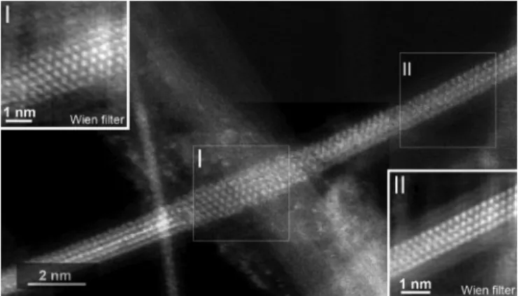
nan-otube. For instance, the fragments in regions I and II in Fig. 2 (see insets) show different projections of the same structure. Both fragments do not exhibit the same width, suggesting that the tube cross-section should correspondingly exhibit an oval instead of circular profile, and that the oval profile is twisted along the tube axis, as previously observed in the literature for other encapsulated crystals [12], [13]. In images such as in Fig. 2, the NiI2 nature of the encapsulated crystal was ascertained by local EELS analysis. The actual spectra corresponding to
Fig. 1. Crystal structure and common projections observed for NiI2 [11]. In
this figure, iodine is depicted by large purple spheres and nickel is depicted by small grey spheres.
Fig. 2. ADF image of an encapsulated NiI2 nanocrystal. The insets are
two ‘Wien’ filtered images of boxed regions I and II, which are produced using the ‘HRTEM Filter’ program developed by D. R. G. Mitchell (see http://www.dmscripting.com/hrtem_filter.html).
the encapsulated crystal of Fig. 2 are not provided here, but an example of what the EELS spectra look like is shown in Figs. 4(bottom) and 6(b).
The corresponding simulated ADF images and models de-rived from both regions (Fig. 3) reveal that fragment II is imaged parallel to a fairly unusual projection ([21-0.5]) with respect to the bulk R-3mH structure in Fig. 1, and the orientation of frag-ment I is perpendicular to that of fragfrag-ment II (see end-on view). In addition, NiI2crystal in region I is 5-atom-thick, thereby dif-fering from the 4-atom-thick fragment II, which possibly arises from the expansion of the inner cavity of the host DWCNT or, alternatively, makes the tube cross-section adopt an oval shape to accommodate the crystal dimension variation, as previously suggested. Another example of twisted NiI2 crystals is
illus-trated in Fig. 4.
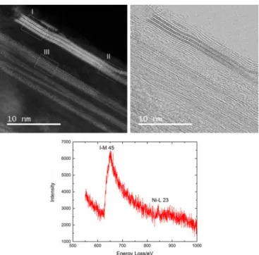
For the confined NiI2 nanowires at the top of the ADF image
in Fig. 4, a three-strip texture is unambiguously seen in region I, whereas at region II, the crystal splits into two strips but is also rotated. Apparently, fragment I corresponds to the combination of three 2D NiI2crystal layers viewed along [1]–[10] projection as suggested by the corresponding structure model and related simulated ADF image (Fig. 5, top). When it comes to region II, the fragment is slightly rotated with respect to fragment I (by
NIE et al.: UNEXPECTED COMPLEXITY OF FILLING DWCNTs WITH NICKEL (AND IODINE) 1-D NANOCRYSTALS 761
Fig. 3. The figure relates to both regions I and II in Fig. 2: “ADF”= duplicates
of the inset images in Fig. 2; “MODEL”= corresponding structure models (side
views); “END-ON”= corresponding cross-section views of the NiI2fragments.
In the models, iodine is depicted by large purple spheres and nickel is depicted by small blue spheres. “SIM”= corresponding simulations of the ADF images
based on the structure models. Matching the related experimental ADF images is then a good indicator that the modelled structure is correct.
Fig. 4. ADF (top left) and bright field STEM (top right) images of the same encapsulated NiI2nanocrystals showing different projected structures in regions
I, II and III. Bottom: EEL spectrum showing the NiI2nature of the crystal.
Meanwhile, the splitting of fragment II should be due to the ‘opening up’ of the host CNT, as observed in the bright field image (Fig. 4, right). Beside the twisted structure, another in-triguing feature is also observed for NiI2 crystals, as shown in
region III (Fig. 5, bottom). According to the simulated ADF image, Fragment III is suggested to be viewed along[001] di-rection, which should induce that some atoms at the periphery of the fragment appear dimmer than others (white arrows) due to a smaller atom column thickness which lowers the level of scattered intensity. However, this does not show up in the cor-responding experimental ADF image.
Fig. 5. The figure relates to regions I, II, and III in Fig. 4, respectively: “ADF”= Details of the inset images in Fig. 4; “MODEL” = corresponding
structure models (side views); “END-ON”= corresponding cross-section views
of the NiI2 fragments; “SIM”= corresponding simulation of the ADF images
based on the structure models. On the right side of the experimental image of region II (arrowed area), we see that the structure has indeed peeled apart. Arrows in the simulated ADF image for fragment III point out the presence of Ni atom pairs which appear dimmers than neighbouring ones. In this figure, iodine is depicted by large purple spheres and nickel is depicted by small blue spheres.
B. Structure of Encapsulated Iodine
In the case of filling attempts with NiI2, NiI2@DWCNTs are
duly observed (as just described in the previous section) along with a minor occurrence of I@DWCNTs as revealed by EELS analysis (see Fig. 6).
The reason of this dual chemical nature – I and NiI2– of the
filling materials is explained by the entering of iodine vapours produced from the spontaneous decomposition of NiI2 into the
CNT cavity. The spontaneous decomposition of NiI2during the
filling process can be attributed to the low Gibbs free energy of the decomposition reaction of NiI2 as addressed in our pre-vious work [5]. A significant amount of CNTs are observed to be filled with a remarkable variety of iodine structures includ-ing atomic sinclud-ingle, double, and triple chains, in good agreement with previous observations [14], [15]. It is worth mentioning that tubes containing iodine chains have a much smaller inner diameter compared to the NiI2-filled tubes and that single-atom
wide iodine chains are by far prevalent over double or triple chains, indicating a preference of iodine for nested configura-tion in narrow spaces. The selectivity towards the size of CNTs during the filling process with iodine vapor may be explained by the capillary condensation phenomena, as previously sug-gested in the case of filling with selenium vapour, which behaves similarly [16].
Fig. 7 presents typical ADF images, a structural model, and the corresponding simulated ADF image of 1D-iodine chains. It can be seen (Fig. 7(a), (b) and (e), (f)) that straight iodine chains are commonly observed and the spacing between the iodine atoms are ca. 0.29 nm on the average, similar to the I-I distance reported in [17].
762 IEEE TRANSACTIONS ON NANOTECHNOLOGY, VOL. 16, NO. 5, SEPTEMBER 2017
Fig. 6. NiI2filling experiments. All images are from the same sample batch:
(a) ADF image of NiI2@DWCNTs showing the strip-based texture typical of
encapsulated NiI2(see Figs. 4 and 5); (b) EEL spectrum obtained by summing
the spectra collected along the red line indicated in (a) confirming that the crystal is NiI2; (c) ADF image of a DWCNT filled with a crystal whose structure is
different from that in (a) and is consistent with encapsulated iodine, as proposed in [14]; (d) EEL spectrum obtained by summing the spectra collected along the red line indicated in (c) confirming that the encapsulated crystal is pure iodine (from [5], with permission from Elsevier).
Fig. 7. (a) ADF image of a bundle of CNTs from NiI2@DWCNT sample with
at least four visible 1D iodine-chains (arrowed). (b) Detail from (a) indicating measured distances between I atoms in a chain. (c) and (d) are the corresponding structural model and the related simulated ADF image of a 1D iodine-chain in-side a (7,7)@(12,12) DWCNT. The wall helicities of the model for the DWCNT are derived from (f) where the DWCNT walls are visible. Indeed, (e) and (f) show an ADF image and an enlarged detail of it respectively, showing a DWCNT which contains a 1D iodine chain (large white arrow) in-between the two walls of the DWCNT (small white arrows). Note that in order to accommodate the 1D iodine chain, the inner SWCNT must fit perfectly around the chain in order to retain a linear structure.
Fig. 8. ADF images (STEM operated at 200 kV) of I@DWCNTs obtained from (a) molten iodine and (b) gaseous iodine, both showing single iodine chains.
Complementary experiments were carried-out for reference, consisting in attempting to fill DWCNTs with molten iodine and iodine vapor. The filling behavior of iodine was found similar, as illustrated by Fig. 8, yet with a higher occurrence of crystal (instead of chain) configurations, due to the fact that iodine is now in excess and available for filling any CNT cavity whatever their diameter, as opposed to what happens with iodine material resulting from NiI2 decomposition.
The atomic arrangement of iodine chains was better resolved in the ADF images (Fig. 8) by increasing the accelerating voltage from 80 kV (as in Figs. 2, 4, 6 and 7) to 200 kV. These ADF im-ages clearly confirm that the encapsulated single iodine-chains adopt a linear and straight configuration instead of the helical configuration suggested by Guan et al. [14]. Meanwhile, other polymorphic structures of iodine confined within CNTs demon-strated by Guan et al. [14] are also observed in both samples, such as helical double-chains as presented in Fig. 9.
The maximum separation of the two chains in Fig. 9(c) is measured at∼0.26 nm, which is smaller than that reported for double helix of iodine encapsulated within SWCNTs (0.65 nm in [15] and 0.49 nm in [14]) which is likely to be due to the smaller inner cavity of our DWCNTs (below∼1 nm) with respect to the SWCNTs used in [14], [15]. Hence, the pitch of the double helix may depend on the inner diameter of the host CNT. In addition, the distance between two adjacent nodes of a same double helix is rarely constant as illustrated in Fig. 9(c), i.e.∼18 nm for the first two nodes at top left and∼27 nm for the two nodes at the top right. Such a helix in a DWCNT with variable periodicity is often found in our samples and for helices confined in different tubes, they show different periodicities (see other examples of double helices in Fig. 9).
When the inner diameter of the host CNT is in the range of 1 nm or more, both amorphous-like phase (Fig. 10) and ordered phases of iodine other than linear chains (Figs. 11 and 12) are observed in both samples.
The iodine ordered phase observed in Fig. 11(a)–(c) ex-hibit features similar to the Phase III structure proposed by Guan et al. [13]. This phase was supposed to be a transition phase generated from the transformation of triple-helix iodine chains under the electron beam irradiation, as described in [14]. As we have most often used the STEM mode which required a
NIE et al.: UNEXPECTED COMPLEXITY OF FILLING DWCNTs WITH NICKEL (AND IODINE) 1-D NANOCRYSTALS 763
Fig. 9. Examples of encapsulated twin helical chains of iodine. (a) and (c) in I@DWCNT materials obtained from molten iodine (white arrows); (b) in I@DWCNT sample obtained from gaseous iodine. In (c) three nodes along the helical double iodine chain are arrowed, showing a helix pitch in the range of 20–30 nm. (d) Structural model (top) and simulated ADF image (bottom) of the double chain in (c) with the three nodes indicated by small arrows. (e) End-on (cross-section) structural model and enlargement of a region between two nodes.
Fig. 10. ADF images (STEM operated at 200 kV) of amorphous-like iodine present in I@DWCNT materials obtained from both (a) molten iodine and (b) gaseous iodine (straight filled CNT at bottom left), respectively.
convergent beam with higher dose of electrons (often operated at 200 kV) than the parallel beam used for HRTEM (operated at 120 kV only) in [14], it is possible that triple-helix iodine chains were present in the materials but did not survive the electron ir-radiation and quickly transformed into this “Phase III” structure. This phase was also observed to be not so much stable under the electron beam and this could be the reason why we also observed amorphous-like iodine filling in ADF (STEM) images operated at 200 kV (Fig. 10). Therefore, the phase transforma-tion of triple-helix iodine chains is ongoing during the TEM observation, which may account for the commonly observed blurred iodine crystals and scarcely observed triple-helix iodine chains in our samples (one ADF image illustrating a possible triple iodine helical-chain is however shown in Fig. 11(d)).
When the inner diameter of the host CNT is larger than 1.5 nm, encapsulated iodine chains are no longer observed but
crys-Fig. 11. (a) ADF image (acquired at 80 kV) of an ordered phase of io-dine present in the Ni@DWCNT material obtained from the H2 reduction of
NiI2@DWCNT material, yet it is assumed that the reduction process has nothing
to do with the occurrence of this structure. the inset in (a) is the EEL spectrum obtained by summing the Angstr¨om-probe spectra collected along the red line across the filled tube, identifying the filling as pure iodine; (b) and (c) HRTEM images (acquired at 100 and 200 kV, respectively) showing an ordered phase of iodine in sample NiI2@DWCNTs. This phase resembles the iodine Phase III
structure proposed by Guan et al [15] which is shown in both images as an inset (see text); (d) ADF image (acquired at 200 kV) of a triple iodine helical-chains (the two nodes of the chains are indicated by red arrows, the configuration of the triple-chains can be seen clearly in white-arrowed region).
Fig. 12. ADF images of iodine crystals with the orthorhombic structure of different thickness (from I@DWCNT material obtained from molten iodine (see text)): (a) an iodine crystal consisting of four parallel lines (from [5], with permission from Elsevier) and (b) an iodine crystal consisting of six parallel lines.
talline iodine with identical structure to the bulk orthorhom-bic iodine crystals may fully develop, which is in agreement with the work by Guan et al. [14]. An example is given in Fig. 12(a) showing an ADF image of crystallized iodine filling in a triple-walled CNT with an inner cavity of 1.71 nm. The filling material exhibits four parallel lines inside the CNT with an average spacing of 0.368 nm, close to the 0.359 nm{200} d-spacing of orthorhombic iodine [18]. Only one example of such
764 IEEE TRANSACTIONS ON NANOTECHNOLOGY, VOL. 16, NO. 5, SEPTEMBER 2017
Fig. 13. ADF images showing a peculiar configuration of iodine (white ar-rows) when the host CNT are large, found: (a) and (b) in I@DWCNT filled with gaseous iodine; (c) in NiI2@DWCNT material; (d) in I@DWCNT filled with
molten iodine.
an encapsulated iodine crystal with the orthorhombic structure was reported in the literature [15], and our observations are fully consistent with it.
In addition, crystalline iodine containing up to 6 parallel lines were also observed inside large CNTs (Fig. 12(b)). The average spacing between the parallel lines is also measured at 0.368 nm for the thicker iodine crystals.
It should be noted that such orthorhombic crystals are rarely observed in the NiI2@DWCNTs sample, which could be
ex-plained by the reason already stated above, i.e., the propensity of iodine resulting from NiI2 decomposition (hence not in
ex-cess as opposed to filling conditions when using pure molten or vaporized iodine) to preferably fill CNTs with narrow cavities. Finally, a new configuration for iodine filling confined within CNTs which has not been reported in the literature was occa-sionally observed in all the samples (i.e., CNTs filled with NiI2, molten iodine, and gaseous iodine) (Fig. 13(a)–(d)). It generally occurred when host CNTs exhibit fairly large diameters, and can be described in two ways: (i) either as a coating of the host CNT inner surface by iodine, thereby resulting in making an in-ner iodine nanotube whose wall is probably amorphous; (ii) or as a large yet flattened tube whose flattening event has created SWCNT-like channels at both edges, so-called dogbone-type CNTs, subsequently filled by iodine (Fig. 14(a) and (b)).
Such large and flattened tubes have already been reported in the literature for both SWCNTs and DWCNTs [19], and fullerene molecules have been already demonstrated to be able to fill their edge channels [20], [21]. Because of the observed irregular shapes (see Fig. 13(d)) which is quite consistent with the aspect of ribbon-like objects once folded and bent, and be-cause of the dark contrast exhibited by the center sof each of
Fig. 14. (a) Model of a large SWCNT once flattened, thereby exhibiting edge channels. (b) Cross- section and top views of a flattened tube as in (a), with the edge channels filled with a foreign material. Models provided by C. Ewels (IMN, Nantes).
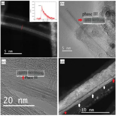
Fig. 15. (a) ADF image at low magnification of the Ni@DWCNT material obtained fromH2-reduction of the NiI2@DWCNT material. The very bright
particle is a residual Co catalyst crystal remaining from the DWCNT growth process. The crystal structure of the encapsulated crystal fragment boxed in (a) is enlarged in (b); (c) EEL spectrum collected from the Ni nanocrystal shown in (b); (d) Projected atomistic model derived from the Ni crystal imaged in (b) based on the structure of bulk Ni in a[111] projection(see text).
the tubes involved, which is barely consistent with the existence of an inner iodine tube (which would cause the contrast to look brighter than it is, we believe), we presume that the cases imaged in Fig. 13 do correspond to flattened tubes filled with iodine at edges as sketched in Fig. 14.
C. Structure of Encapsulated Ni
After reduction under hydrogen of the NiI2@DWCNT
ma-terial, we observed encapsulated crystals exhibiting a signif-icant contrast difference compared to neighboring ones as shown in Fig. 15(a). These crystals were identified as pure Ni by EELS analysis. Typical atomically-resolved ADF im-age and EEL spectrum of the encapsulated Ni nanocrystals are illustrated by Fig. 15(b) and (c). It is worth noting that the projected structure of the encapsulated Ni crystal imaged in Fig. 15(b) was tentatively modelled based on the regular struc-ture of bulk Ni crystal in a[111] projection. Quite interestingly,
NIE et al.: UNEXPECTED COMPLEXITY OF FILLING DWCNTs WITH NICKEL (AND IODINE) 1-D NANOCRYSTALS 765
Fig. 16. (a) and (b) ADF images of encapsulated crystals showing contrast variations in Ni@DWCNTs_500_7; (c) to (f) are the corresponding EEL spec-tra collected from positions 1 to 4 indicated by arrows in (b), respectively. Meanwhile, the absence of any signal in spectrum (e) demonstrates the spatial resolution of the electron probe.
the projection fits well the experimental image provided the dis-tances between the Ni atom columns are stretched by 25–29%. This is huge strain, and it is likely that the actual structure is not that of bulk Ni but is an unprecedented one instead, yet to determine.
In addition, some tubes are segmentally filled while showing peculiar contrast variations as demonstrated by ADF images such as in Figs. 16(a), (b) and 17. The elemental composition of the segments along the axis of the nanocrystals following the axis of the nanotube was investigated by EELS analysis. Four typical EEL spectra collected from different segments encapsulated in the same tube as shown in Fig. 16(b) are dis-played as Fig. 16(c)–(f). It can be seen that the elemental com-position of the encapsulated segments varies along the axis di-rection. The encapsulation of iodine in position 1 (Fig. 16(c))
Fig. 17. (a) HRTEM image of aNiIx crystal with longitudinally variable
composition; (b) and (c) EEL spectra collected from fragment (1) and (2), respectively.
may result from the decomposition of previously existing NiI2 nanocrystals, in which case resulting Ni was pushed out from the tube while iodine has remained within the cavity of the tube. Segment in position 2 (Fig. 16(d)) still corresponds to NiI2
hav-ing not been subjected to reduction yet. Since position 3 is void, neither Ni edge nor I edge is present in the spectrum (Fig. 16(e)), meanwhile illustrating the spatial resolution of the probe.
When it comes to position 4 (Fig. 16(f)), the segment exhibits an intermediate composition (NiIx,x < 2) between NiI2 and
Ni since the I M45/NiL23 intensity ratio is much lower than
for genuineNiI2. Such an intermediate may originate from the
uncomplete reduction of NiI2byH2or from the partial
decom-position of NiI2 before the reduction event. Thanks to other
evidences, the former case is more likely. Indeed, a meaningful example is provided in Fig. 17. An encapsulated crystal showing different contrasts is displayed in Fig. 17(a) and the elemental composition of the two positions arrowed (white arrows) ob-tained by EELS (Fig. 17(b) and (c)) shows that the dark part of the crystal (location 1) is depleted in iodine with respect to the light-grey part of the crystal (location 2), respectively, the latter being comparable to the EEL spectrum obtained on pureNiI2
(see Fig. 6(b) for instance).
The results suggest that the diffusion ofH2into the cavity of
CNTs starts from the tip of the tube and then, the diffusion ofH2
is very slow as it has to proceed through theNiI2crystal (and/or
in the crystal/inner tube interspace, as suggested by the pecu-liar contrast at this very location – black arrows in Fig. 17(a)) thus resulting in the incomplete removal of iodine atoms for the dark segment (1) near the tip while leaving the rest of the crystal with the nearly unchanged NiI2 composition (2). Thus, the transition from NiI2 to I2 or to NiIx (x < 2) within the
same tube indicates the anisotropic reactivity of encapsulated NiI2 along the axis direction of nanotubes. On the other hand,
766 IEEE TRANSACTIONS ON NANOTECHNOLOGY, VOL. 16, NO. 5, SEPTEMBER 2017
several studies have shown that the tips of CNTs which can be opened by molten iodides during the filling step may reseal upon cooling [22], [23], and this also possibly account for the formation of segment (1) in Fig. 17(a). It is possible that the tip of the nanotube in Fig. 17(a) was partly resealed during the cooling process, leaving a very limited entrance (yet the open-ing does not show up) for the incomopen-ing diffusion ofH2, thereby
slowing down the kinetics of the reaction betweenH2andNiI2.
The resealing of CNTs is also consistent with the presence of unreduced NiI2 nanocrystals in the Ni@DWCNT sample even after a 24-h reaction in our work.
IV. CONCLUSION
In this paper, nickel iodide and iodine have been successfully introduced into DWCNTs mostly via the molten phase method or occasionally by the gas phase method (in the case of iodine). Peculiar structures were observed for the confined NiI2 and io-dine with respect to bulk materials. Especially in the case of iodine, those structures include atomic iodine chains either sin-gle and straight, or twins (or triple) and helical, iodine crystals with structure differing from that of bulk iodine, iodine crystals with the orthorhombic structure as in bulk, amorphous iodine, and probable dogbone-type CNTs with iodine-filled edges. The various structural configurations of iodine appear to be closely related to the inner diameter of the host CNT, and also whether iodine is available in excess or not. Furthermore, reduction post-treatment with hydrogen on NiI2@DWCNTs aiming to obtain
Ni nanocrystals was carried out and the resulting encapsulated Ni crystals exhibited peculiar crystalline structure, either similar to bulk Ni crystal but with up to 29% stretched atom distances, or unprecedented and yet to determine. The investigation of the crystal structure of encapsulated NiI2, iodine and Ni demon-strated that the confinement of the inner cavity of CNTs can induce modified structures, or even new structures. Hence, it now would be of great interest to perform measurements on the electrical conductivity of DWCNTs filled with iodine chains, iodine crystals or iodine-filled dogbone CNTs and further make a comparison among them, as well as measuring the magnetic properties of Ni-filled DWCNT material, that the recurrently remaining iodine content or the heavily stretched (or new, alter-natively) structure are likely to strongly alter.
REFERENCES
[1] M. Monthioux, “Filling single-wall carbon nanotubes,” Carbon, vol. 40, no. 10, pp. 1809–1823, 2002.
[2] M. Monthioux, E. Flahaut, and J.-P. Cleuziou, “Hybrid carbon nanotubes: Strategy, progress, and perspectives,” J. Mater. Res., vol. 21, no. 11, pp. 2774–2793, 2006.
[3] L. Grigorian et al., “Reversible intercalation of charged iodine chains into carbon nanotube ropes,” Phys. Rev. Lett., vol. 80, no. 25, p. 5560, 1998. [4] T. Michel et al., “Structural selective charge transfer in iodine-doped
carbon nanotubes,” J. Phys. Chem. Solids, vol. 67, no. 5, pp. 1190–1192, 2006.
[5] C. Nie, A.-M. Galibert, B. Soula, E. Flahaut, J. Sloan, and M. Monthioux, “A new insight on the mechanisms of filling closed carbon nanotubes with molten metal iodides,” Carbon, vol. 110, pp. 48–50, Dec. 2016. [6] E. Philp et al., “An encapsulated helical one-dimensional cobalt iodide
nanostructure,” Nature Mater., vol. 2, no. 12, pp. 788–791, 2003. [7] J. Sloan et al., “Metastable one-dimensional AgCl1 −xIx solid-solution
Wurzite “Tunnel” crystals formed within single-walled carbon nanotubes,”
J. Am. Chem. Soc., vol. 124, no. 10, pp. 2116–2117, 2002.
[8] J. Sloan et al., “Two layer 4:4 co-ordinated KI crystals grown within single walled carbon nanotubes,” Chem. Phys. Lett., vol. 329, no. 1, pp. 61–65, 2000.
[9] Y. Sakurabayashi, M. Monthioux, K. Kishita, Y. Suzuki, T. Kondo, and M. Le Lay, “Tailoring double-wall carbon nanotubes?,” AIP Conf. Proc., vol. 685, pp. 302–305.
[10] E. Flahaut et al., “Crystallization of 2H and 4H PbI2in carbon nanotubes
of varying diameters and morphologies,” Chem. Mater., vol. 18, no. 8, pp. 2059–2069, 2006.
[11] J. Ketelaar, “Die Kristallstruktur des Nickelbromids und-jodids,”
Zeitschrift Kristallographie-Crystalline Mater., vol. 88, no. 1-6, pp. 26–34,
1934.
[12] J. Sloan, A. I. Kirkland, J. L. Hutchison, and M. L. Green, “Aspects of crystal growth within carbon nanotubes,” Comptes Rendus Phys., vol. 4, no. 9, pp. 1063–1074, 2003.
[13] N. Thamavaranukup et al., “Single-walled carbon nanotubes filled with MOH (M= K, Cs) and then washed and refilled with clusters and
molecules,” Chem. Commun., vol. 2004, no. 15, pp. 1686–1687, 2004. [14] L. Guan, K. Suenaga, Z. Shi, Z. Gu, and S. Iijima, “Polymorphic structures
of iodine and their phase transition in confined nanospace,” Nano Lett., vol. 7, no. 6, pp. 1532–1535, 2007.
[15] X. Fan et al., “Atomic arrangement of iodine atoms inside single-walled carbon nanotubes,” Phys. Rev. Lett., vol. 84, no. 20, p. 4621, 2000. [16] J. Chancolon, F. Archaimbault, A. Pineau, and S. Bonnamy, “Filling of
carbon nanotubes with selenium by vapor phase process,” J. Nanoscience
Nanotechnol., vol. 6, no. 1, pp. 82–86, 2006.
[17] M. Chorro et al., “1D-confinement of polyiodides inside single-wall car-bon nanotubes,” Carcar-bon, vol. 52, pp. 100–108, 2013.
[18] R. M. Ibberson, O. Moze, and C. Petrillo, “High resolution neutron powder diffraction studies of the low temperature crystal structure of molecular iodine (I2),” Mol. Phys., vol. 76, no. 2, pp. 395–403, Jun. 1992.
[19] D. Choi et al., “Fabrication and characterization of fully flattened car-bon nanotubes: a new graphene nanoribcar-bon analogue,” Sci. Rep., vol. 3, p. 1617, 2013.
[20] H. R. Barzegar et al., “C60/Collapsed carbon nanotube hybrids: A variant of peapods,” Nano Lett., vol. 15, no. 2, pp. 829–834, 2015.
[21] Q. Wang, R. Kitaura, Y. Yamamoto, S. Arai, and H. Shinohara, “Synthesis and TEM structural characterization of C60-flattened carbon nanotube nanopeapods,” Nano Res., vol. 7, no. 12, pp. 1843–1848, 2014. [22] L. Shao, G. Tobias, Y. Huh, and M. L. H. Green, “Reversible filling of
single walled carbon nanotubes opened by alkali hydroxides,” Carbon, vol. 44, no. 13, pp. 2855–2858, 2006.
[23] G. Brown et al., “High yield incorporation and washing properties of halides incorporated into single walled carbon nanotubes,” Appl. Phys. A, vol. 76, no. 4, pp. 457–462, 2003.