HAL Id: hal-01907583
https://hal.archives-ouvertes.fr/hal-01907583
Submitted on 29 Oct 2018HAL is a multi-disciplinary open access archive for the deposit and dissemination of sci-entific research documents, whether they are pub-lished or not. The documents may come from teaching and research institutions in France or abroad, or from public or private research centers.
L’archive ouverte pluridisciplinaire HAL, est destinée au dépôt et à la diffusion de documents scientifiques de niveau recherche, publiés ou non, émanant des établissements d’enseignement et de recherche français ou étrangers, des laboratoires publics ou privés.
Densification of Ni and TiAl by SPS: kinetics and
microscopic mechanisms
Zofia Trzaska, Robin Cours, Jean-Philippe Monchoux
To cite this version:
Zofia Trzaska, Robin Cours, Jean-Philippe Monchoux. Densification of Ni and TiAl by SPS: kinetics and microscopic mechanisms. Metallurgical and Materials Transactions A, Springer Verlag/ASM International, 2018, 49 (10), pp.4849 - 4859. �10.1007/s11661-018-4775-0�. �hal-01907583�
1
Densification of Ni and TiAl by SPS: kinetics and microscopic mechanisms
Zofia Trzaska1, Robin Cours2, Jean-Philippe Monchoux2*
1 LSPM CNRS UPR 3407, and Université Sorbonne Paris Cité, 99 Avenue Jean-Baptiste Clément, 93430 Villetaneuse, France.
2 CEMES CNRS UPR 8011, and Université de Toulouse, 29 Rue Jeanne Marvig, 31055 Toulouse, France.
* Corresponding author: [email protected]
Abstract
Densification by spark plasma sintering (SPS) of ductile (Ni) and brittle (TiAl) metallic materials have been studied to elucidate the mechanism of densification in the two cases. Isothermal densification experiments were carried out to determine the activation parameters in Ni. Transmission electron microscopy (TEM) observations of thin foils extracted by focused ion beam (FIB) in the contact regions between particles of TiAl and Ni powders are presented. Macroscopically, the most striking feature observed here is that the densification of Ni takes place in the wide temperature range of 0.2–1.0 Tm, whereas that of TiAl varies in 0.7–0.9 Tm, which is significantly narrower (Tm being the melting temperature of Ni and the peritectic temperature of TiAl). In Ni, the low activation energy (164 ± 30 kJ/mol), the high dislocation density in the inter-particle contact region, and the formation of recovery cells involving dislocation climb, indicate that the rate-controlling mechanism is probably self-diffusion in dislocations. In TiAl, high dislocation densities leading to reorganization into sub-boundaries point to dislocation climb mechanisms, which are kinetically controlled by volume diffusion. The difference in densification kinetics between Ni and TiAl is then accounted for in terms of the difference in their respective rate-controlling mechanisms operative during densification.
2
1. Introduction
The aim of this study is to identify the densification mechanisms during spark plasma sintering (SPS) of two metallic systems, Ni and TiAl, which exhibit typical mechanical behaviors in being, respectively, ductile and brittle. This study is interesting from a fundamental point of view, because the impact of the high temperature constitutive relations on the kinetics of densification can be clearly illustrated using these two emblematic cases. Moreover, the nature of the microscopic mechanisms operative during a SPS cycle is a matter of intense debate in the research community, principally due to the spectacular rapidity of densification that can be achieved by this technique [1, 2]. Therefore, the process of densification deserves a careful identification of the underlying mechanisms, on both macroscopic and microscopic scales. Finally, precisely characterizing the densification cycles of metallic materials that exemplify the behavior of many alloys is technologically interesting, since an increasing number of research groups are also interested in the potential of the SPS to prepare novel materials where the level of densification of the final product is crucial.
The SPS process consists in uniaxially pressing a powder at high temperature in the presence of an electric current of high intensity, by which, remarkably high densification kinetics can be induced. According to various previous studies, the applied current is believed to result in generating arcs/plasma [3–10], local Joule overheating at the junctions of the powder particles [11–16], acceleration of dislocation motion [17, 18] and atom diffusion [1]. These effects lead to kinetics of densification [19] and synthesis [20] up to 10 times faster than those obtained when conventional synthesis techniques are used. However, previous studies on metallic systems, one on Cu [21], and the other on TiAl by our team [22], clearly show that the applied current during SPS does not have any influence on the densification kinetics, which is then when comparable to conventional hot pressing (HP) technique. This can be accounted for by the fact that the applied current does not cause local overheating at the necks between the powder particles; this aspect has been theoretically modeled in millimetric [23] and micrometric [24] metallic powders. Another study on the Ag-Zn system [25] showed that under typical SPS conditions, the electric current does not induce an acceleration of diffusion. As diffusion is the elementary mechanism of the plasticity processes and therefore controls their kinetics [22], it is probably not surprising that the current has no influence on the densification rate. In summary, there is no real evidence that under identical conditions, SPS is intrinsically faster than other conventional techniques. Hence, in this report, we consider that the densification
3 mechanisms are driven by the applied macroscopic pressure and by the temperature, without any influence of the applied current.
Densification of TiAl under pressure was first investigated using the hot isostatic pressing (HIP) technique by Choi et al. [26], where power law creep was identified to be the densification mechanism from an analysis of macroscopic kinetics. Densification by SPS has been studied using elemental [27, 28] and pre-alloyed [22, 29–36] powders. Results reported in these studies showed that densification occurs in a few minutes [22, 29, 31, 36], and that the kinetics depends on the initial microstructure of the powder particles [32, 35]. The densification mechanism consists in a deformation of the powder particles [31] similar to that in HIP [26]. The measured macroscopic activation parameters (stress exponent n and activation energy Q) of the Norton law describing the deformation of the powder particles (n = 1.9 ± 0.3,
Q = 308 ± 20 kJ/mol), were close to those measured under identical experimental conditions by
hot pressing [22] indicating that Al volume self-diffusion was the rate controlling mechanism. On a microscopic scale, studies using transmission electron microscopy (TEM) of thin foils extracted at the necks between TiAl powder particles during densification by focused ion beam (FIB) have shown intense deformation of the neck region, the plasticity mechanisms being twinning, glide and climb [36]. Therefore, the kinetics was probably controlled by climb, and, consequently, by diffusion, which is in agreement with results from macroscopic studies. Recrystallization nuclei were also observed in the intensely deformed regions, indicating a dynamic recrystallization mechanism, which resulted in a microstructure that was mostly recrystallized at the end of the densification process [31].
We believe that the densification of micrometric Ni could be similar to that of Cu; the latter has been analyzed in the classic papers from Ashby’s team [37], where it was predicted that Cu powder made of polycrystalline particles of 150 µm diameter with 10 µm grain size would predominantly densify by what is referred to as “power-law creep”, that is, a plastic deformation at high temperature through a combination of dislocation mechanisms (glide and glide + climb), following a significant instantaneous plastic yield due to a low yield strength. Nabarro-Herring and Coble mechanisms were expected to occur only for very long isothermal durations (more than about 5 h at 550°C), and can be reasonably excluded from the discussion in our study. However, no microscopic evidences were provided in support of these interpretations made from macroscopic observations. With respect to Ni, many studies have focused on mainly using the rapidity of SPS to stabilize very fine grains while densifying nanometric powders. Original bi-modal microstructures made of small (≈ 1 µm) and large (≈ 100 µm) grains have
4 thus been obtained [38–44]. Oxides at the surface of the powder particles have been identified to negatively impact the cohesion of the material after densification by SPS of nanometric Ni powders [44], leading to low ductility in compression [40] and in tension [43]. However, despite this drawback, nanostructured Ni-based materials exhibiting very high accumulated strains during cyclic tests have been obtained [38]. Densification studies on Ni powder (powder particle size of 4.3 µm) using specially designed experimental setups showed that the density after isothermal cycles (750°C/15 MPa/10 min) is larger when all the current of the SPS passes through the sample (D =0.95) than when the sample is insulated from the current (D =0.89). This result seems to point to an influence of the electric current on the elementary densification mechanisms (for example, diffusion and plasticity), but no interpretation was given [45]. Another study showed the influence of processing parameters (such as mold size) on the microstructure of Ni samples after densification, but the evolution of the microstructure during the SPS cycle was not investigated [46]. Lastly, a densification kinetics study has shown that mechanically-activated Ni powders (≈ 8 µm particle size) required lower sintering temperatures (800°C instead of 1000°C) for full densification [47], which was attributed to the effect of grain size and defect density on the densification mechanisms; however, an in-depth discussion on these effects was not presented.
From the above analysis of literature, we conclude that under pressure, the densification mechanisms that have been identified are climb-controlled glide followed by recovery and recrystallization for TiAl, and glide + climb for Ni. However, if accurate microstructure studies have been reported for TiAl, this has not been the case for Ni. Our aim here therefore, is to precisely characterize microscopically, the densification mechanisms under conditions of SPS, of Ni and also to further explore the densification of TiAl. For both the cases, macroscopic densification kinetics have been determined and microscopic characterization using EBSD and TEM of interrupted states during densification, has been carried out. In particular, we present original TEM images of thin foils extracted by FIB at the junctions between powder particles.
2. Experimental
Ni powder (25-75 µm in particle size, Metallied) and gas-atomized TiAl powder (Crucible Industries) with the composition Ti48.7Al47.3Cr1.9Nb2 with particle sizes in the range 100– 150 µm, have been selected for their spherical morphologies. The powders were annealed by SPS prior to the experiments (1100°C – 5 min for Ni and 1200°C – 5 min for TiAl) to equilibrate their microstructure, while taking special care to ensure that no pressure was applied on the
5 powders. In the case of TiAl, it was necessary to anneal the powder since a transformation from the out-of-equilibrium microstructure of the as gas-atomized powder particles to the equilibrium + 2 microstructure occurs during densification at ≈ 700–900°C, and this simultaneous occurrence of phase transformation and densification could complicate the interpretation of data [31]. TEM studies indicated that the resulting powder particles have a recrystallized microstructure [36]. Therefore, we decided to anneal the Ni powder also, so that both the powders were in recrystallized state at the start of the experiments. After annealing, the powders were de-agglomerated by manually grinding them in an agate mortar for ~ 10 min.
The SPS cycles, the procedure to calibrate the temperature, and to determine the densification curves have been described in detail elsewhere [22]. The most relevant parameters are summarized in the following. For the microstructure studies, 1.2 g of TiAl and 1.8 g of Ni powders were filled into 8 mm diameter graphite molds so as to have a sample thickness of ≈ 4–8 mm, depending on the relative density. However, to obtain accurate measurements of relative density, samples of larger diameter but with lower thickness were necessary in order to minimize friction on the lateral walls of the molds [48]. Thus, for the measurement of relative density, molds 20 mm in diameter were employed, with 3.92 g (for TiAl) and 8.38 g (for Ni) of powder, giving a sample thickness of 3 mm at full density. A Sumitomo 2080 SPS machine was used; the chamber was first evacuated to ≈ 10 Pa, after which, the uniaxial pressure was applied in 1 min and the temperature cycle was programmed to increase at the rate of 100°C/min. In the interrupted experiments, the heating was switched off when the desired temperature was reached during the ramp. In the isothermal experiments, the 100°C/min ramp was followed by a hold time at constant temperature (to avoid overshooting, the heating rate was reduced to 25°C/min, 3 min before reaching this temperature). In the temperature drop experiments, the temperature was programmed to rapidly decrease (in 1 min) in steps of 50– 100°C. The time for temperature equilibration after the rapid decrease typically lasted 5 min. In all the experiments, the SPS cycle was terminated by switching off the current followed by releasing the pressure and the molds cooled down naturally at the rate of 250–500°C/min. The temperature was measured by an optical pyrometer (above 570°C) or by a thermocouple (between room temperature and 1000°C). For TiAl, densification occurred at temperatures above ≈ 800°C, due to which, the pyrometer was employed in the whole temperature range, but for Ni, since densification occurred between room temperature and 1300°C, it was necessary to use a thermocouple for experiments below 1000°C, and the pyrometer for experiments performed above this temperature. It was not possible, with our apparatus, to switch from the
6 thermocouple to the pyrometer during an experiment. However, to limit errors introduced due to employing two different measurement techniques, calibrations were performed by accurately measuring the melting points of Al, Cu, and the transus temperature of TiAl, as detailed in previous studies [22]. This calibration was also useful to correct measurement errors because, while either using the optical pyrometer or the thermocouple, the temperature is measured on the external walls of the molds, which is different from the sample temperature by typically 25– 90°C, depending on the mold diameter and on the temperature. The corresponding calibration curves are given in Fig. 1.
Fig. 1. Temperature calibration curves for 8 mm and 20 mm molds.
Sample relative density D (the ratio of the sample density at time t during the cycle to the theoretical density) has been determined geometrically by measuring the thickness and diameter of the samples, and by weighing them. Densification curves have been traced using the displacement of the lower punch of the SPS, from which the contributions from elastic and thermal deformations of the machine have been subtracted using blank tests; more details can be found in a previous paper [22]. The resolution of the punch displacement was ± 0.01 mm, which yields an accuracy in D of about ± 0.0015. However, most of the error on the determination of the densification curves comes from errors in measuring the geometry of the dense samples (thickness, diameter). Such errors may originate in the correction of the punch displacement using results obtained in blank tests, and/or from fluctuations caused by vibrations generated by the SPS machine, load instabilities, etc. We evaluate these contributions to lead
7 to an error in D of ± 0.01 on an average; error bars for each experiment have been added in the graphs.
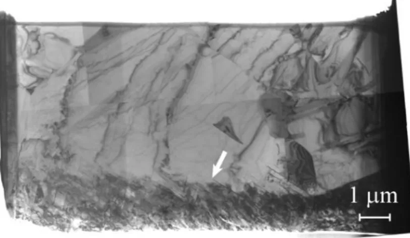
For microstructure investigations (EBSD, FIB), the samples were cut parallel to the pressure axis of the SPS. Surface sample preparation for EBSD investigations consisted in polishing with SiC papers and diamond pastes down to 1 µm followed by finishing with 2/3 colloidal silica – 1/3 H2O2 for one hour. This procedure was delicate because the samples were in a porous state and not completely consolidated. Careful cleaning by sonicating in an ultrasonic bath between the successive steps of the polishing procedure was carried out to remove particles of grinding papers or pastes (SiC, diamond) accumulated in the pores of the samples. FIB lift-outs of Ni thin foils for TEM analysis have been performed using a FEI Helios Nanolab 600i apparatus; to prepare lift-outs of TiAl, a previously published procedure was followed [36]. Special care was taken to avoid irradiation damages and in cases where the thin foils suffered excessive irradiation, these were discarded. Fig. 2 shows an example of a thin foil extracted from a well recrystallized TiAl sample, i.e. free of defects (dislocations, loops, debris, which could be confused with irradiation damages). The zone at the bottom of the image (indicated by the arrow) shows such irradiation damages. Since damaged areas were invariably found in all the thin foils, care was taken to perform investigations far away from these areas. EBSD analyses were performed using a detector (Oxford) integrated into the the FEI Helios system. Typical operating conditions were as follows: Acceleration voltage: 20 keV, beam current: 11 nA, map dimensions: 200 µm × 177 µm, step: 0.25 µm, and total acquisition time: 15 h. TEM observations were carried out with a Jeol 2010 microscope.
Fig. 2. TEM image of an entire thin foil extracted by FIB from a well recrystallized TiAl sample. The arrow shows a zone containing irradiation damages.
8
3. Results
3.1. Densification curves
Fig. 3 shows the evolution of the densities of TiAl and Ni samples as a function of temperature. These systems exhibit markedly different behaviors. For TiAl, densification begins at ≈ 900°C and finishes at ≈ 1250°C; the entire process thus takes place in a temperature range of ≈ 350°C. Conversely, the densification of Ni extends over a much wider temperature range, beginning near room temperature, and ending above 1300°C (full density could not be reached before melting of the sample), that is, at temperatures > 1300°C. With respect to the melting temperature Tm, the densification of TiAl occurs in the interval 0.7–0.9 Tm (Tm being here, the peritectic temperature, 1476°C), and the densification of Ni occurs in the interval 0.2– 1.0 Tm (with Tm = 1455°C).
Fig.3. Density as a function of temperature for TiAl and Ni. Each data point gives the geometrical density of the samples as a function of the sample temperature in interrupted experiments.
3.2. Activation parameters
To quantitatively account for the differences in densification kinetics between TiAl and Ni, the activation parameters have been determined for Ni and compared with those of TiAl determined in another study [22]. Moreover, in the present study, the activation energy has been
9 determined using temperature jumps on identical samples, which is believed to be more rigorous than the method employed in our previous study [22], where several samples were required. The stress jump method has also been attempted here, but proved to be not convenient because of too slow kinetics, as explained below.
To determine the activation parameters, the following relations have been employed under the assumption that the densification mechanism obeys the power-law creep [37, 49]:
𝜀̇ = 𝐴0exp (−𝑅𝑇𝑄) 𝜎𝑛, (1)
where Q is the activation energy, n, the stress exponent, 𝜀̇ is the deformation rate of the material making up the powder particles, and A0 is a material constant. If the contributions from capillary forces and from the gas trapped in the pores to the effective pressure are disregarded, the densification rate 𝐷̇ and the equivalent stress are then given by:
𝐷̇ = 𝐺1(𝐷)𝜀̇ (2) 𝜎 = 𝐺2(𝐷)𝑃 (3) for D < 0.9: 𝐺1(𝐷) = 5,3(𝐷2𝐷 0)1 3⁄ 1 √3( 𝐷 − 𝐷0 1 − 𝐷0) 1 2⁄ (4) 𝐺2(𝐷) = 1 3× 1 − 𝐷0 𝐷2(𝐷 − 𝐷 0) (5) and for D > 0.9: 𝐺1(𝐷) = 3 2× 𝐷(1 − 𝐷) [1 − (1 − 𝐷)1 𝑛⁄ ]𝑛 (6) 𝐺2(𝐷) = 3 2𝑛 (7)
where P is the applied macroscopic pressure and 𝐷0 is the green density. The above relations show that the plot of ln 𝐷̇ = 𝑓 (1𝑇) for different temperatures at constant P is a straight line with the slope (−𝑄
𝑅), and the plot ln 𝐷̇ = 𝑓(ln 𝜎) for different values of P at constant T yields a straight line with slope n.
Thus, measuring the temperature drop allows to determine different values of ln 𝐷̇, from which Q can be obtained. The advantage of this method is that the microstructure is identical just before and just after the drop, at least in theory. In practice, however, small microstructure
10 evolutions cannot be avoided, but can be minimized when cooling drops are employed. Furthermore, due to the high cooling rates in SPS (of the order of 250–500°C/min), the programmed temperature after the jump is reached in about 5 min, during which microstructure evolution is believed to be negligible. Fig. 4a shows examples of temperature drops of 53°C and 100°C on the densification curves of Ni; note that these curves have been corrected by subtracting the punch displacement contribution obtained from blank experiments. Steeper temperature drops (150°C and above) have been attempted, but the 𝐷̇ values were too low to be estimated with sufficient accuracy. Following each jump, the curves remained unstable with fluctuations during 5 min; in these regions, due to transitory phenomena, the curve does not represent the actual D(t) function. Hence, the values of 𝐷̇ have been evaluated outside these perturbed regions. Since the curves exhibit discontinuous steps due to acquisition of the punch displacement in steps of 0.01 mm, linear fitting has been performed on portions of the curve to obtain 𝐷̇ values from the slope of the fits (Fig. 4a). Here, acquiring data for longer times could improve accuracy, but in this case, it is also necessary that the microstructure (sizes of grains and of recovery cells, dislocation substructure, etc.) remains unchanged after the temperature drop. This imposes a limit on the duration during which the densification rate can be measured. Here, we have considered 15 min of acquisition after the jump to be a good compromise that allows to obtain a sufficient accuracy in measurement. Fig. 4b shows the plot of ln 𝐷̇ = 𝑓 (1𝑇) from data thus obtained, wherefrom, an activation energy of 164 ± 30 kJ/mol is obtained.
11
Fig. 4. (a) Examples of temperature drops on Ni densification curves. (b) Arrhenius plot of 𝐷̇ as a function of 1/T.
We have tried to use the stress jump method to evaluate stress exponent values, but this resulted in highly noisy curves, leading to high inaccuracy. The reason for this behavior can be understood by considering the isothermal densification curves shown in Fig. 5. As can be seen, the curves are rather flat, indicating that the isothermal densification kinetics is slow. Moreover, changing the applied pressure P from 50 MPa to 25 MPa resulted in even slower kinetics. This means that experiments of long durations (more than one hour) would be necessary to obtain a
12 high enough evolution of D to correctly evaluate the slopes of the densification curves before and after the jumps.
Fig. 5. Isothermal densification curves of Ni under 50 MPa.
Next, we employed the method developed by Bernard-Granger et al. [48, 50, 51]. The main advantage of this method is that it takes into account the whole densification curve in the evaluation of n, but has the drawback that the microstructure and the mechanisms may not be constant during the experiment. The following expressions have been employed:
ln [ 1 𝜇eff 𝐷̇ 𝐷] = 𝑛ln [ 𝜎eff 𝜇eff] + 𝐾 (8) 𝜇eff = 𝐸 2(1 + 𝜈) 𝐷 − 𝐷0 1 − 𝐷0 (9) 𝜎eff = 1 − 𝐷0 𝐷2(𝐷 − 𝐷 0)𝑃 (10)
where E is the Young’s modulus (= 214 GPa), , the Poisson’s ratio (= 0.3), D0, the green
density (= 0.6) and K is a constant. Using the above relations, the stress exponent has been evaluated for isothermal densifications (Fig. 6), fitting the D(t) functions by sixth order
13 polynomials to accurately evaluate the 𝐷̇(𝑡) functions. According to Eq. (8), straight lines are expected, but it is seen that a linear behavior is observed only for the central portions of the curves. Outside these linear regions, mathematical divergences occur. High values of 𝜎eff⁄𝜇eff (right parts of the curves) result from D tending towards D0 (Eq. 10), leading to unrealistically high values for D very close to D0. This probably accounts for the fact that the model fails to reproduce the experiments for these portions of the curves. Moreover, the n values, given by the slope of the curves, would diminish when eff is increased. This would mean a decrease of
n with increasing applied stress, which is in contradiction with trends usually observed in high
temperature deformation experiments. For low values of 𝜎eff⁄𝜇eff, the curves asymptotically tend towards −∞. This is because, low values of 𝜎eff correspond to the D(t) functions asymptotically reaching constant values (Fig. 5). Then, 𝐷̇(𝑡) tends towards zero, and Eq. (8) (which gives the ordinate of Fig. 6) tends towards −∞, and again, the model is not in accordance with the experimental behavior. These mathematical problems point to the limits of the models from which Eq. (8–10) have been derived. Therefore, we have determined n only for the central parts of the curves. Because of these mathematical problems, the obtained n values, between 2.5 and 4.6, are only qualitative.
Fig. 6. Plot of 𝑙𝑛 [𝜇1 eff 𝐷̇ 𝐷] as a function of 𝑙𝑛 [ 𝜎eff 𝜇𝑒ff]. 3.3. Microstructural characterization
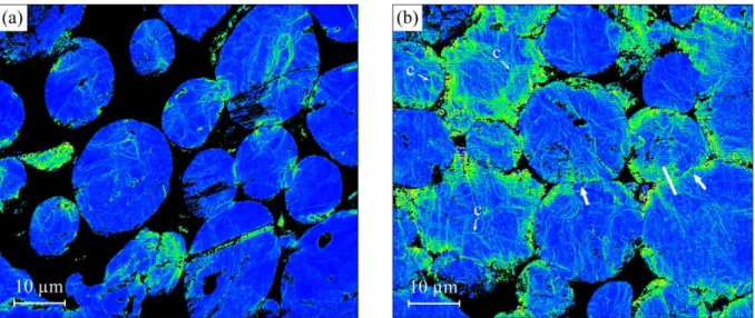
14 Figs. 7 and 8a show microstructure characterization of the recrystallized Ni powder by EBSD and TEM. Fig. 7a shows that the particles are constituted of large metallurgical grains, and that the grain sizes are of the same order of magnitude as the particle sizes. TEM analysis of a bulk recrystallized Ni sample, shows a clean microstructure, containing only few dislocations (Fig. 7b). The microstructure of Ni samples during densification are illustrated in Figs. 8b and 9 including maps of local misorientations drawn from EBSD analyses of the recrystallized powder (Fig. 8a) and of a sample densified at 512°C (Fig. 8b). This representation shows the change in the amplitude of crystalline orientation from point to point in the sample and thus reveals deformed regions in the material. In the recrystallized powder (Fig. 8a), it is seen that the particles exhibit some deformed regions (in yellow), but on an average, remain mostly undeformed (blue regions), whereas, during densification (512°C, D ≈ 0.7, Fig. 8b), many deformed regions appear, principally at the periphery of the particles. A striking feature is that the deformed zones form lines, which organize into ill-defined cells of about 5 µm in diameter. Fig. 9 shows a TEM image of a thin foil extracted by FIB in the neck region between two powder particles (727°C, D ≈ 0.75), that is, in a region similar to that indicated in Fig. 8b. Globally, the FIB-thinned foil exhibits a high density of dislocations, considerably more than in the recrystallized state (Fig. 7b). Moreover, the image at higher magnification (Fig. 9b) shows that the dislocations form cells (indicated by arrows) of about 1 µm in diameter. This observation confirms that the yellow lines in Fig. 8 are actually cell boundaries. These boundaries are in the form of walls of ~ 0.05–0.1 µm in thickness, in which the dislocations are concentrated.
Fig. 7. (a) EBSD map of Ni powder particles after recrystallization heat treatment. (b) TEM images of a bulk recrystallized Ni sample.
15
Fig. 8. EBSD local misorientation images of (a) Initial recrystallized Ni powder particles. (b) Particles during densification by SPS (512°C, D ≈ 0.7). The arrows indicate example of necks between powder particles, approximately perpendicular to the pressure axis (vertical). The white segment indicates the typical length (≈5-10 µm) and location of FIB thin foils extracted at the necks. Examples of deformation cells (labeled as c) are indicated.
Fig. 9. TEM images of thin foils extracted by FIB at the junction between two Ni particles in a sample densified at 727°C (D ≈ 0.75). (a) Entire thin foil. (b) Detail of the zone delimited by the rectangle. Arrows point to dislocation walls.
For TiAl, the microstructure of the recrystallized powder particles is near with 4% vol. of 2 phase. EBSD grain size maps (Fig. 10a) show that the powder is composed of polycrystalline particles with a grain size of 4 µm [36], that is, smaller than the particle size (≈ 100 µm); it is seen that the grains are clean and free of dislocations (Fig. 10b) confirming that the powder is in a recrystallized state. During densification, EBSD grain size maps reveal that the grains are significantly smaller in the deformed regions close to the necks [36], but also
16 in the particles which are globally deformed (Fig. 11a). Maps of local misorientations by EBSD for these samples did not give any interesting information, presumably due to the absence of dislocation cells boundaries. TEM observations of FIB thin foils extracted at the necks show three kinds of zones with grains containing a high density of dislocations (Fig. 11b), grains where the dislocations reorganize into sub-boundaries (Fig. 11c), and recrystallized grains (Fig. 11d). Note that the dislocations do not arrange into walls as in the case of Ni (Fig. 9b), but into sub-boundaries.
Fig. 10. (a) EBSD grain size map of the recrystallized TiAl powder. (b) TEM image of a thin foil prepared from the recrystallized powder.
17
Fig. 11. Micrographs of TiAl samples densified at 1137°C (D ≈ 0.9). (a) EBSD grain size map. Note that in the intensely deformed particle at the center of the micrograph, the grains appear globally in blue, meaning that their average size is lower than those of the surrounding particles. (b–d) TEM images of thin foils extracted by FIB at the junction between two powder particles, showing (b) high dislocation densities, (c) dislocations rearranging into sub-boundaries and (d) recrystallized grains.
4. Discussion
The macroscopic densification of Ni extends over a wide temperature interval (Fig. 3), which is a consequence of the low value of the activation energy of this process (164 ± 30 kJ/mol, Fig. 4b). This value can be compared with activation energies for diffusion mechanisms from which, the main mechanism controlling the densification of Ni can be determined. Literature values of activation energies for volume and grain boundary diffusion are ≈ 280 kJ/mol and ≈ 100–140 kJ/mol, respectively [52]. The reported value for volume diffusion is significantly higher than our measurements, which indicates that the densification
18 of Ni is most likely not controlled by this mechanism. The reported activation energy of grain boundary diffusion is closer to our measured value, but this mechanism can also be excluded because the microstructure, which was initially in a recrystallized state and made of large grains, remained coarse-grained throughout the densification, which means that the mass flux through the grain boundaries is probably very low. In the literature, the activation energy for the high temperature deformation of pure Ni is reported to be 234 kJ/mol, a value that has been associated to dynamic recrystallization mechanisms [53]; this aspect will be discussed below. As far as the stress exponent n is concerned, the qualitatively determined values in the range between 2.5 and 4.6 are compatible with literature data (n = 4.6 [54]). Usually, high values of
n are correlated to dislocation mechanisms, which is the case in the present study.
At the scale of the Ni powder particles, most of the plastic deformation occurs at the periphery of the particles, where they are in contact with each other. A previous study [36] based on TEM observations on lift-outs by FIB of thin foils showed that locally, the plastic deformation was heterogeneous, being higher at the inter-particle contacts than at the particle centers. In this study, EBSD maps (Fig. 8b) give a better description of the repartition of the plastic deformation, which extends over about ¼ of the radius of the particles. For 𝜀̇ = 10-3 s-1, the yield stress of bulk Ni at 500°C (calculated with data from Ref. [55]) is ~ 250 MPa. According to Eq. (10), under an applied pressure of 50 MPa, eff is higher than 250 MPa for D up to ≈ 0.75. In other words, severe plastic deformation occurs locally in the neck regions, despite the fact that the macroscopic applied pressure (50 MPa) is lower than the yield stress (250 MPa). In the deformed region, the dislocations arrange to form a complex structure of cells, with sizes varying from 1 µm (Fig. 9) to > 5 µm (Fig. 8b). This phenomenon could result from recovery mechanisms, according to which the dislocations rearrange into cells walls, and then into sub-boundaries [56]. However, the formation of new grains by recrystallization has been reported in the literature. This mechanism, which was experimentally observed by Luton
et al. [53] and controlled the kinetics, does not occur in our case. In the study of Luton et al.,
the high strain rates (between 2×10⁻³ s-1 and 4 s-1) and strains (up to 400 %) favored recrystallization mechanisms. Under typical SPS conditions, the equivalent strain rate as described in Ref. [36], is 10-3 s-1, and the equivalent strain deduced by integration of the strain rate curve of Ref. [36] is about 25 %. Obviously, these are average values and the actual strain and strain rates are probably very different in different areas of the powder particles. However, their magnitudes probably do not reach the values given in the study of Luton et al., which is probably the reason for the difference in recrystallization behavior observed in our study. Thus,
19 we believe that the stress relaxation occurs by recovery, without recrystallization. On the microscopic scale, the elementary mechanism controlling the recovery is probably dislocation climb, because for dislocations to arrange into walls, it needs the degrees of freedom provided by contributions from climb. This means that diffusion is the rate-controlling mechanism, since it controls the rate of climb. The observed discrepancy between the activation energy for densification (164 ± 30 kJ/mol) and that for self-diffusion (≈ 280 kJ/mol) is surprising, but diffusion in dislocations is also a possibility that needs to be considered [56]. Literature values of activation energies for diffusion in dislocations are 170 kJ/mol and 187 kJ/mol for edge and screw dislocations, respectively [57]; these values are close to that observed in our experiment.
As compared to Ni, the temperature interval for the densification of TiAl is narrower (~ 350°C for TiAl, whereas, it is > 1300°C for Ni as shown in Fig. 3). This indicates that the activation energy of TiAl, 308 ± 20 kJ/mol, determined in a previous work [22], is higher than that of Ni, which is 164 ± 30 kJ/mol. In this previous work, it was concluded that the rate-controlling elementary mechanism was self-diffusion of Al in TiAl, in agreement with the activation energy for this mechanism (360 kJ/mol [58]); the low n values (1.9 ± 0.3 [22]) also point to a diffusion mechanism operative in this case. On the microscopic scale, densification occurs by plastic deformation of the inter-particle contacts, inducing high dislocation densities in these regions (Fig. 11b). Dislocation analyses in another study showed that plasticity is accompanied by climb-controlled glide [36]. The presence of sub-boundaries (Fig. 11c) is indicative of recovery mechanisms in TiAl similar to Ni. However, the dislocations are arranged into walls of 0.05–0.1 µm thickness in Ni, and into sub-boundaries in TiAl. This difference could be due to higher line tension in TiAl, which results in less degrees of freedom to the dislocations than in Ni, where dislocations could be less organized. Furthermore, clean grains (Fig. 11d) as well as grain refinement (Fig. 11a) show that dynamic recrystallization occurs in TiAl, in contrast to Ni. Thus, diffusion involved in dislocation climb and in sub-grain formation is the elementary rate-controlling mechanism in TiAl, as in the case of Ni.
Finally, the mechanisms proposed above can be compared to those observed with conventional sintering techniques involving mechanical pressure, which are mentioned in the introduction. For TiAl, power-law creep was identified as the microscopic densification mechanism in HIP experiments [26], and dislocation climb controlled by Al diffusion in HP experiments [22]; in both cases, the mechanism was identified on the basis of densification kinetics analyses. In the present work, dislocation climb mechanisms are observed by TEM, proving that mechanisms in SPS are similar to those reported in HIP and HP experiments. For
20 the case of Ni, it is useful to refer to the very closely related example of Cu, where power-law creep by dislocation glide and glide+climb was observed in HIP experiments [37]; SPS experiments described in our study show similar mechanisms. However, we propose here that diffusion in dislocations could be the rate-controlling mechanism. Thus, it appears that for both the systems studied, TiAl and Ni, the SPS mechanisms are similar to those reported in conventional techniques such as HIP and HP. In particular, no specific effect seems to be triggered by the electric current used in SPS.
In summary, densification occurs by plastic deformation of the interparticle contacts for both TiAl and Ni and the kinetics probably depends on elementary diffusion mechanisms in volume for TiAl, and in dislocations for Ni. Relaxation of the deformation occurs by recovery and recrystallization for TiAl, and by recovery alone for Ni.
5. Conclusions
A comparison of sintering by SPS of TiAl and Ni powders has been performed in order to evaluate the influence of brittle and ductile mechanical behaviors on the densification kinetics of metallic materials. Spherical powders have been selected, which were recrystallized by heat treatment prior to experiments. Densification occurred in the ranges 0.7–0.9 Tm and 0.2–1.0 Tm for TiAl and Ni, respectively, where Tm is the peritectic temperature for TiAl and the melting temperature for Ni. For Ni, an activation energy Q of 164 ± 30 kJ/mol and a stress exponent n in the range 2.5–4.6 have been determined from isothermal densification curves. For TiAl, the values Q = 308 kJ/mol and n = 1.9, were taken from our previous study. With respect to TiAl, the wider temperature range of densification of Ni is then a consequence of a lower activation energy. However, TEM observations show that, for both Ni and TiAl, Densification results from plastic deformation of the regions close to the inter-particle contacts. In the case of Ni, EBSD observations show that the deformed regions extend over roughly ¼ of the radius of the particles. FIB lift-outs of TEM thin foils in the deformed regions at the inter-particle contacts have been performed for both Ni and TiAl. In the case of Ni, a high density of dislocations arranged into walls 0.05–0.1 µm thick, was observed. These walls defined cells of ~ 1–5 µm in diameter, characteristic of recovery. In the case of TiAl, EBSD observations showed that the grains are refined in the deformed regions, and TEM observations of these regions showed a microstructure constituting grains containing high densities of dislocations, accompanied by recovered and recrystallized grains. Recovery being an indication of a diffusion-controlled dislocation climb mechanism, we propose that the rate-controlling mechanism is volume
21 diffusion of Al for TiAl, and diffusion in dislocations for Ni, since these mechanisms have activation energies which are comparable to our measured values (Q = 360 kJ/mol for self-diffusion of Al in TiAl [58], and Q = 170–187 kJ/mol for self-diffusion in dislocations in Ni [57]).
Acknowledgements
This work was financially supported by a grant within the framework of the MF2-ANR-2011-PBS09-020 project of the French “Agence Nationale de la Recherche”. SPS experiments have been performed using the Sumitomo 2080 SPS machine at the “Plateforme Nationale de Frittage Flash du CNRS” (PNF2-CNRS, Paul Sabatier University, Toulouse, France).
References
[1] Z.A. Munir, U. Anselmi-Tamburini, M. Ohyanagi: J. Mater. Sci, 2006, vol. 41, pp. 763-777.
[2] R. Orru, R. Licheri, A.M. Locci, A. Cincotti, G. Cao: Mater. Sci. Eng. R, 2009, vol. 63, pp. 127-287.
[3] M. Tokita: Mater. Sci Forum, 1999, vol. 308-311, pp. 83-88. [4] M. Omori: Mater. Sci. Eng. A, 2000, vol. 287, pp. 183-188. [5] K. Okazaki: Mater. Sci. Eng. A, 2000, vol. 287, pp. 189-197.
[6] J.R. Groza, A. Zavaliangos: Mater. Sci. Eng. A, 2000, vol. 287, pp. 171-177.
[7] O. Yanagisawa, H. Kuramoto, K. Matsugi, Komatsu: Mater. Sci. Eng. A, 2003, vol. 350, pp. 184-189.
[8] R. Marder, C. Estournès, G. Chevallier, R. Chaim: Scripta Mater., 2014, vol. 82, pp. 57-60. [9] R. Marder, C. Estournès, G. Chevallier, R. Chaim: J. Mater. Sci., 2015, vol. 50, pp.4636-4645.
[10] T. Saunders, S. Grasso, M.J. Reece: J. Eur. Ceram. Soc., 2015, vol. 35, pp. 871-877. [11] T. Grosdidier, G. Ji, F. Bernard, E. Gaffet, Z.A. Munir, S. Launois: Intermetallics, 2006, vol. 14, pp. 1208-1213.
[12] G. Ji, T. Grosdidier, N. Bozzolo, S. Launois: Intermetallics, 2007, vol. 15, pp. 108-118. [13] J.M. Frei, U. Anselmi-Tamburini, Z.A. Munir: J. App. Phys., 2007, vol. 101; p. 114914. [14] S. Nowak, L. Perrière, L. Dembinski, S. Tusseau-Nenez, Y. Champion: J. Alloys and
Compounds, 2001, vol. 509, pp. 1011-1019.
[15] Y. Xiong, D. Liu, Y. Li, B. Zheng, C. Haines, J. Paras, D. Martin, D. Kapoor, E.J. Lavernia, J.M. Schoenung: Metall. Mat. Trans A, 2012, vol. 43A, pp. 327-339.
22 [17] H. Conrad, A.F. Sprecher, W.D. Cao, X.P. Lu: JOM, 1990, vol. 42, pp. 28-33.
[18] B.R. Livesay, N.E. Donlin, A.K. Garrison, H.M. Harris, J.L. Hubbard: International
Reliability Physics Symposium, IEEE, 1992, p. 217.
[19] Z. Shen, M. Johnson, Z. Zhao, M. Nygren: J. Am. Ceram. Soc., 2002, vol. 85, pp. 1921-1927.
[20] G. Jouan, M. Dollé, J.P. Monchoux: Solid State Ionics, 2013, vol. 236, pp. 5-10.
[21] R. Collet, S. Le Gallet, F. Naimi, F. Charlot, S. Lay, G. Bonnefont, G. Fantozzi, J.M. Chaix, F. Bernard: J. Alloys and Compounds, 2017, vol. 692, pp. 478-484.
[22] Z. Trzaska, G. Bonnefont, G. Fantozzi, J.P. Monchoux: Acta Mater., 2017, vol. 135, pp. 1-13.
[23] J. Trapp, B. Kieback: J. Am. Ceram. Soc., 2015, vol. 98, pp. 3547-3552.
[24] C. Collard, Z. Trzaska, L. Durand, J.M. Chaix, J.P. Monchoux: Powder Technology, 2017, vol. 321, pp. 458-470.
[25] Z. Trzaska, J.P. Monchoux: J. Alloys and Compounds, 2015, vol. 635, pp. 142-149. [26] B.W. Choi, Y.G. Deng, C. McCullough, B. Paden, R. Mehrabian: Acta Metal. Mater., 1990, vol. 38, pp. 2225-2243.
[27] H.A Calderon, V. Garibay-Febles, M. Umemoto, M. Yamaguchi: Mater. Sci. Eng. A, 2002, vol. 329-331, pp. 196-205.
[28] Y.Y. Chen, H.B. Yu, D.L. Zhang, L.H. Cha: Mater. Sci. Eng. A, 2009, vol. 525, pp. 66-73. [29] A. Couret, G. Molénat, J. Galy, M. Thomas: Intermetallics, 2008, vol. 16, pp. 1134-1141. [30] X. Lu, X.B. He, B. Zhang, L. Zhang, X.H. Qu, Z.X. Guo: Intermetallics, 2009, vol. 17, pp. 840-846.
[31] H. Jabbar, A. Couret, L. Durand, J.P. Monchoux: J. Alloys and Compounds, 2011, vol. 509, pp. 9826-9835.
[32] J. Guyon, A. Hazotte, J.P. Monchoux, E. Bouzy: Intermetallics, 2013, vol. 34, pp. 94-100. [33] Vajpai S.K., Ameyama K: Intermetallics, 2013, vol. 42, pp. 146-155.
[34] Z. Trzaska, A. Couret, J.P. Monchoux. 5th International Symposium on High Temperature
Metallurgical Processing, proceedings of TMS 2014, February 16-20, San-Diego, Wiley, 2014,
pp. 329-336.
[35] T. Shanmugasundaram, J. Guyon, J.P. Monchoux, A. Hazotte, E. Bouzy: Intermetallics, 2015, vol. 66, pp. 141-148.
[36] Z. Trzaska, A. Couret, J.P. Monchoux: Acta Mater., 2016, vol. 118, pp. 100-108. [37] A.S. Helle, K.E. Easterling, M.F. Ashby: Acta Metal., 1985, vol. 33, pp. 2163-2174.
23 [38] G. Dirras, S. Bouvier, J. Gubicza, B. Hasni, T. Szilagyi: Mater. Sci. Eng. A, 2009, vol. 526, pp. 201-210.
[39] G. Dirras, J. Gubicza, S. Ramtani, Q.H. Bui, T. Szilágyi: Mater. Sci. Eng. A, 2010, vol. 527, pp. 1206-1214.
[40] Q.H. Bui, G. Dirras, S. Ramtani, J. Gubicza: Mater. Sci. Eng. A, 2010, vol. 527, pp. 3227-3235.
[41] G. D. Dutel, D. Tingaud, P. Langlois, G. Dirras: J. Mater. Sci., 2012, vol. 47, pp. 7926-7931.
[42] G.D. Dutel, P. Langlois, D. Tingaud, G. Dirras: Mater. Charac., 2013, vol. 79, pp. 76-83. [43] L. Farbaniec, G. Dirras, A. Krawczynska, F. Mompiou, H. Couque, F. Naimi, F. Bernard, D. Tingaud: Mater. Charac., 2014, vol. 94, pp. 126-137.
[44] D. Tingaud, P. Jenei, A. Krawczynska, F. Mompiou, J. Gubicza, G. Dirras: Mater. Charac., 2015, vol. 99, pp. 118-127.
[45] L. Minier, S. Le Gallet, Y. Grin, F. Bernard: J. Alloys and Compounds, 2010, vol. 508, pp. 412-418.
[46] L. Minier, S. Le Gallet, Y. Grin, F. Bernard: Mater. Chem. Phys., 2012, vol. 134, pp. 243-253.
[47] F. Naimi, L. Minier, S. Le Gallet, H. Couque, F. Bernard: J. Nanomaterials, 2013, vol. 2013, Article ID 674843.
[48] G. Bernard-Granger, C. Guizard: Acta Mater., 2007, vol. 55, pp. 3493-3504. [49] E. Arzt, M.F. Ashby, K.E. Easterling: Metal. Trans. A, 1983, vol. 14, pp. 211-221.
[50] G. Bernard-Granger, A. Addad, G. Fantozzi, G. Bonnefont, C. Guizard, D. Vernat: Acta
Mater., 2010, vol. 58, pp. 3390-3399.
[51]. L. Ramond, G. Bernard-Granger, A. Addad, C. Guizard: Acta Mater., 2010, vol. 58, pp. 5120-5128.
[52] Landolt-Bornstein, Numerical Data and Functional Relationships in Science and Technology, Group III: Crystal and Solid State Physics, Volume 26: Diffusion in Solid Metals and Alloys. Springer, Berlin, 1990.
[53] M.J. Luton, C.M. Sellars: Acta Metal., 1969, vol. 17, pp. 1033-1043. [54] J. Weertman, P. Shahinian: Trans. AIME, 1956, vol. 206, pp.1223-1226.
[55] H.J. Frost, M.F. Ashby: Deformation-mechanism maps, Pergamon Press, Oxford, 1982. [56] F.J. Humphreys, M. Hatherly. Recrystallization and related annealing phenomena, Elsevier, Oxford, 2004.
24 [58] C. Herzig, T. Przeorski, Y. Mishin: Intermetallics, 1999, vol. 7, pp. 389-404.
25
Figure captions
Fig. 1. Temperature calibration curves for 8 mm and 20 mm molds.
Fig. 2. TEM image of an entire thin foil extracted by FIB from a well recrystallized TiAl sample. The arrow shows a zone containing irradiation damages.
Fig.3. Density as a function of temperature for TiAl and Ni. Each data point gives the geometrical density of the samples as a function of the sample temperature in interrupted experiments.
Fig. 4. (a) Examples of temperature drops on Ni densification curves. (b) Arrhenius plot of Ḋ as a function of 1/T.
Fig. 5. Isothermal densification curves of Ni under 50 MPa.
Fig. 6. Plot of ln [μ1 eff Ḋ D] as a function of ln [ σeff μeff].
Fig. 7. (a) EBSD map of Ni powder particles after recrystallization heat treatment. (b) TEM images of a bulk recrystallized Ni sample.
Fig. 8. EBSD local misorientation images of (a) Initial recrystallized Ni powder particles. (b) Particles during densification by SPS (512°C, D ≈ 0.7). The arrows indicate example of necks between powder particles, approximately perpendicular to the pressure axis (vertical). The white segment indicates the typical length (≈5-10 µm) and location of FIB thin foils extracted at the necks. Examples of deformation cells (labeled as c) are indicated.
Fig. 9. TEM images of thin foils extracted by FIB at the junction between two Ni particles in a sample densified at 727°C (D ≈ 0.75). (a) Entire thin foil. (b) Detail of the zone delimited by the rectangle. Arrows point to dislocation walls.
Fig. 10. (a) EBSD grain size map of the recrystallized TiAl powder. (b) TEM image of a thin foil prepared from the recrystallized powder.
Fig. 11. Micrographs of TiAl samples densified at 1137°C (D ≈ 0.9). (a) EBSD grain size map. Note that in the intensely deformed particle at the center of the micrograph, the grains appear globally in blue, meaning that their average size is lower than those of the surrounding particles. (b–d) TEM images of thin foils extracted by FIB at the junction between two powder particles, showing (b) high dislocation densities, (c) dislocations rearranging into sub-boundaries and (d) recrystallized grains.