Design and Evaluation of a Quasi-Passive Robotic
On the Effects of Parallel Elasticity
on Human Running
by
Grant A. Elliott
S.B. Physics
S.B. Electrical Engineering and Computer Science
Massachusetts Institute of Technology (2006)
M.Eng. Electrical Engineering and Computer Science
Massachusetts Institute of Technology (2007)
Submitted to the Department of
Electrical Engineering and Computer Science
ARCHIVES
MASSACHUSETTS INSi E
OF TECHNOLOGY
MAR 2 0
2012
LIBRARIES
in partial fulfillment of the requirements for the degree of
Doctor of Philosophy in Electrical Engineering and Computer Science
at the
MASSACHUSETTS INSTITUTE OF TECHNOLOGY
February 2012
@
Massachusetts Institute of Technology 2012. All rights reserved.
A uthor ...
...
Department
Certified by...
Accepted by...
Electrical Engineering and Computer Science
Jan 13, 2012
Hugh Herr
Associate Professor of Media Arts and Sciences
n-~A
i.ThesisSupervisor
\6
cLIie A. Kolodziejski
Chair of the Committee on Graduate Students
Knee Brace:
Design and Evaluation of a Quasi-Passive Robotic Knee
Brace: On the Effects of Parallel Elasticity on Human
Running
by
Grant A. Elliott
Submitted to the Department of Electrical Engineering and Computer Science on Jan 13, 2012, in partial fulfillment of the
requirements for the degree of
Doctor of Philosophy in Electrical Engineering and Computer Science
Abstract
While the effects of series compliance on running biomechanics are documented, the effects of parallel compliance are known only for the simpler case of hopping. As many practical exoskeleton and orthosis designs act in parallel with the leg, it is desirable to understand the effects of such an intervention. Spring-like forces offer a natural choice of perturbation, as they are both biologically motivated and energetically inexpensive to implement.
To this end, this thesis investigates the hypothesis that the addition of an external elastic element at the knee during the stance phase of running results in a reduction in knee extensor activation so that total joint quasi-stiffness is maintained. To test this, an exoskeleton is presented, consisting of a leaf spring in parallel with the knee joint and a clutch which engages this spring only during stance. The design of a custom interference clutch, made necessary by the need for high holding torque but low mass, is discussed in detail, as are problems of human attachment. The greater applicability of this clutch design to other problems in rehabilitation and augmentation is also addressed.
Motion capture of four subjects is used to investigate the consequences of running with this exoskeleton. Leg stiffness is found to increase with distal mass, but no sig-nificant change in leg stiffness or total knee stiffness is observed due to the activation of the clutched parallel knee spring. However, preliminary evidence suggests differing responses between trained marathon runners, who appear to maintain biological knee torque, and recreational runners, who appear to maintain total knee torque. Such a relationship between degree of past training and effective utilization of an external force is suggestive of limitations on the applications of assistive devices.
Thesis Supervisor: Hugh Herr
Acknowledgments
I would like to acknowledge the contributions of Prof. Hugh Herr, without whom this
would not have been possible, and all the members of the MIT Biomechatronics Group who have assisted me over the years. Particular thanks go to my officemates Ernesto Martinez and Michael Eilenberg, who suffered alongside me all those sleepless nights and who edited this document, my old friend Arthur Petron, who provided many an outlet, my long-suffering UROP Andrew Marecki, who contributed greatly to the design of the clutch, and the wholly inimitable Bruce Deffenbaugh, who offered an endless stream of good advice and taught me how to make an anatomically correct rubber chicken. A truly exceptional debt of gratitude is owed to Jared Markowitz,
whose patience and generosity know no bounds.
I would also like to thank Bob Emerson, our prosthetist; without his exceptional craftsmanship, I would be left with a wonderful device and no way to wear it.
An additional thanks goes to Prof. Greg Sawicki of North Carolina State Uni-versity and his Human PoWeR lab, including Dominick Farris and Ben Robertson, for generously offering their time and the use of their equipment to collect the data presented here.
On a more personal note, thank you to my family, Richard, Patricia, and Tucker Elliott, for their support these last five years and my entire life.
Contents
1 Introduction
1.1 Existing Lower Limb Exoskeletons . . . 1.2 Kinetics and Kinematics of Running .
1.3 Augmentation of Hopping and Running
2 Human Attachment 2.1 Joint Geometry . . . . 2.2 Harness Evolution . . . . 3 Mechanical Design 3.1 Exoskeletal Knee . . . . 3.1.1 Clutch . . . . 3.1.2 Planetary Gearbox . . . . 3.2 Elastic Element . . . . 3.3 Failure Analysis . . . .
3.3.1 Clutch Tooth Bending . . . . . 3.3.2 Spur Gear Tooth Bending . . .
3.3.3 Coupling Torsion . . . .
3.3.4 Linear Bearing Loading . . . .
3.3.5 Planet Bearing Loading . . . .
3.3.6 Ring Bearing Loading . . . . .
4 Control
4.1 Electronics and Instrumentation 4.2 Firmware . . . . 4.2.1 Gait Analysis . . . .
4.2.2 Latency Compensation
4.2.3 Pulse-and-Hold Solenoid. Activation
5 Clinical Testing and Results
5.1 Experimental Design . . . .
5.2 Instrumentation and Processing . . . .
5.3 R esults . . . .
5.3.1 Average Mechanics and Metabolic Demand . . . .
5.3.2 Subject Variation in Response to Intervention . . . .
67 67 70 73 76 80 .
6 Discussion 95 6.1 Conclusions . . . . 95 6.2 Im plications . . . . 95 6.3 Future Improvements . . . . 96 6.4 Future Research . . . . 99 6.5 Other Applications . . . . 100 6.6 Concluding Thoughts . . . . 101 A Varying Stride Frequency 107
B Subject Mechanics and Electromyograhy 113
List of Figures
1-1 Five passive lower limb exoskeletons . . . . 18
(a) Yagn's proposed running exoskeleton . . . . 18
(b) MIT hopping exoskeleton . . . . 18
(c) SpringBuck shoe . . . . 18
(d) PowerSkip . . . . 18
(e) SpringWalker . . . . 18
1-2 Six active and quasi-passive lower limb exoskeletons . . . . 20
(a) Hardiman . . . . 20
(b) Sarcos exoskeleton . . . . 20
(c) BLEEX . . . . 20
(d) H ULC . . . . 20
(e) MIT exoskeleton . . . . 20
(f) H A L . . . . 20
1-3 Spring-mass model of running stance . . . . 22
1-4 Force-displacement curves for effective leg spring during running . . . 23
1-5 Torque-angle curve for knee during running . . . . 23
1-6 Leg stiffness dependence on running speed. . . . . 25
1-7 Leg stiffness dependence on step frequency. . . . . 26
1-8 Collapsable bow spring with exoskeletal knee joint . . . . 27
(a) Unlocked . . . . 27
(b) Locked . . . . 27
(c) Compressed . . . . 27
2-1 Configurations of the elastic exoskeleton . . . . 30
2-2 Possible proximal attachment points . . . . 33
(a) Thigh compression . . . . 33
(b) Pelvis compression, concentric to hip . . . . 33
(c) Pelvis compression, offset from hip . . . . 33
(d) Chest compression . . . . 33
2-3 Possible distal attachment points . . . . 34
(a) Calf compression . . . . 34
(b) Concentric to ankle . . . . 34
(c) Rigid toe . . . . 34
(d) Center of pressure tracking . . . . 34
2-4 Selected harness designs . . . . 35
(b) Thigh cuff harness with toe attachment . . . . 35
(c) Thigh cuff harness with shank attachment . . . . 35
(d) Knee brace harness . . . . 35
2-5 Center of pressure tracking distal attachment . . . . 37
(a) Heel Strike . . . . 37
(b) Midstance . . . . 37
(c) Toeoff . . . . 37
3-1 Commercially available clutches . . . . 42
3-2 Schematic depiction of the designed clutch . . . . 43
3-3 Renders of the exoskeletal knee joint . . . . 44
(a) Fully assembled . . . . 44
(b) Lateral assembly removed . . . . 44
(c) Lateral planet carrier removed . . . . 44
(d) Medial planet carrier removed . . . . 44
(e) Reverse angle with medial components removed . . . . 44
3-4 Exploded view of exoskeletal knee joint . . . . 45
3-5 Clutch plate geometry . . . . 46
3-6 Planetary gearbox geometry . . . . 48
3-7 Finite element division of an elastic strut . . . . 50
3-8 Example large angle deflection of a spring strut . . . . 51
3-9 Torque-angle plot for composite leaf springs . . . . 52
3-10 Partial and full engagement of clutch plates . . . . 55
(a) Partially engaged . . . . 55
(b) Fully engaged . . . . 55
3-11 Finite element analysis of clutch teeth . . . . 59
3-12 Finite element analysis of planetary gear box . . . . 60
3-13 Finite element analysis of couplings . . . . 62
(a) Sun gear rim . . . . 62
(b) Rotating clutch plate . . . . 62
4-1 Circuit board floor plan . . . . 70
4-2 The control framework . . . . 71
4-3 Gait analysis . . . . 75
4-4 Simulation of solenoid latency compensation algorithm . . . . 77
5-1 Markers of the right leg . . . . 85
5-2 Surface electromyography placements . . . . 86
(a) Soleus . . . . 86
(b) Lateral gastrocnemius . . . . 86
(c) Tibialis anterior . . . . 86
(d) Vastus lateralis . . . . 86
(e) Rectus femoris . . . . 86
(f) Biceps femoris . . . . 86
(h) Iliopsoas . . . . 86
5-3 Example metabolic demand calculation... . . . . . . . 87
5-4 Biological and exoskeletal knee stiffness for several subjects . . . . 93
A-i Metabolic demand as a function of step frequency . . . . 109
A-2 Electromyography for three step frequencies . . . . 110
A-3 Electromyographic trends in step frequency . . . . 111
(a) Rectus Femoris . . . III (b) Vastus Lateralis . . . . II1 (c) Gluteus Maximus . . . . 112 (d) Biceps Femoris . . . . 112 B-1 Subject S . . . . 114 (a) Mechanics . . . . 114 (b) Stiffnesses . . . . 115 (c) Electromyography . . . . 116 B-2 Subject S2 . . . . 117 (a) Mechanics . . . . 117 (b) Stiffnesses . . . . 118 (c) Electromyography . . . . 119 B-3 Subject S3 . . . . 120 (a) Mechanics . . . . 120 (b) Stiffnesses . . . . 121 (c) Electromyography . . . . 122 B-4 Subject S4 . . . . 123 (a) Mechanics . . . . 123 (b) Stiffnesses . . . . 124 (c) Electromyography . . . . 125 B-5 Subject S5 . . . . 126 (a) Mechanics . . . . 126 (b) Stiffnesses . . . . 127 (c) Electromyography . . . . 128 B-6 Subject S6 . . . . 129 (a) Mechanics . . . . 129 (b) Stiffnesses . . . . 130 (c) Electromyography . . . . 131
List of Tables
3-1 Design specifications . . . . 3-2 Subscripts used in constants . . . .
3-3 Clutch constants . . . .
3-4 Transmission constants . . . . (a) Gross transmission . . . .
(b) Gears . . . .
3-5 Elastic element and harness constants . . .
3-6 Material constants . . . . 3-7 Summary of failures due to applied torque 3-8 Transmission tooth bending . . . .
4-1 Sensors of the exoskeletal knee . . . . 4-2 Power consumption . . . . (a) Electronics . . . . (b) Solenoid . . . . (c) Total . . . . 4-3 Control variables . . . . 4-4 Control constants . . . . 5-1 Subject measurements
5-2 Subject joint stiffnesses (a) Ankle stiffness
(b) Knee stiffness .
5-3 Subject leg stiffnesses .
5-4 Subject metabolic demands
5-5 Mean of gait characteristics
.. . .. . . .. . . .. . . .. . .. . . .
82
.. . .. . . .. . . .. . . .. . .. . . .
89
.. . .. . . .. . . .. . . .. . . . .. .
89
. .. . . .. .. . . .. . . .. . . . .. .
89
. .. . . .. .. . . .. . . .. . . . .. .
90
. .. . . .. .. . . . .. . . .. . . .. .
90
. .. . . .. . .. . . .. . . .. . . .. .
91
Chapter 1
Introduction
An exoskeleton which successfully modifies human gait to reduce joint loading, muscle fatigue, or metabolic demand of locomotion has applications in several areas:
" Biomechanics: An exoskeleton with proven augmentative capabilities would
be an invaluable research tool in studying neuromuscular control strategies as it permits the selective application of external assistive forces.
" Load Bearing: Soldiers and firefighters, among others, have occupations which
require brisk movement over varying terrain while burdened with significant load. An augmenting exoskeleton could offer a potentially life-saving increase in endurance or capability while potentially also reducing damaging loads on the knee and ankle.
" Mobility and Recreation: The prevalence of knee injury poses both health
and quality of life problems. A device which permits an active lifestyle by reducing the load on an injured joint could mitigate these. In cases of severe joint damage, such an exoskeleton could also be used as a walking orthosis to permit normal walking in patients with otherwise limited mobility. Moreover, the purely recreational benefits of any device which permits extended activity cannot be overlooked.
Despite this utility, metabolic augmentation of human locomotion has proved an elusive goal. Though a number of exoskeletons have been built (see Section 1.1), none
has demonstrated a significant reduction in the metabolic demand of locomotion. This thesis considers the problem of building an exoskeleton to accommodate run-ning gait. As discussed in Sectionl.2, the knee is known to behave largely elastically. Because of this, an appropriate external assistive force may be applied during stance phase using a low mass passive spring in parallel with the joint. If the neuromuscular system responds to such an external force by reducing activation of the knee exten-sors, total
metabolic
demand or loading in thejoint
may decrease. Unfortunately, the effects of such parallel elasticity are relatively uninvestigated to date.This thesis addresses the hypothesis that the addition of an external elastic ele-ment at the knee during the stance phase of running results in a reduction in knee extensor activation so that total joint quasi-stiffness is maintained. If true, metabolic demand may be reduced if an external stiffness near that of the biological joint is applied. This question is investigated with measurements of joint kinematics and ki-netics, electromyography, and total metabolic demand. The results inform the design of future exoskeletons and orthoses.
1.1
Existing Lower Limb Exoskeletons
Exoskeletons may loosely be classified as intended to augment human capabilities, such as load capacity or ambulatory speed, or to increase human endurance, by low-ering the metabolic demand of a given activity. While the ultimate intent of the exoskeleton described here is to reduce muscle activation and increase endurance in running, this discussion considers both types of devices as the division is frequently blurred. For instance, a device intended to reduce the metabolic demand of a move-ment may alternatively permit the execution of that movemove-ment at higher speed for a given metabolic demand. Moreover, some orthotic devices, intended to restore lost functionality, may be thought of as exoskeletons.
Additionally exoskeletons are classified as passive, quasi-passive, or active based on their usage of power. Passive exoskeletons require no energy source and generally consist of linkages, springs, and dampers. Active devices, in contrast, add energy to
the human gait cycle, usually through motors or hydraulic cylinders. Quasi-passive devices lie between, unable to inject energy into the gait cycle, but nonetheless requir-ing a power supply, usually to operate electronic control systems, clutches, or variable dampers. Typically, though not necessarily, the power requirement of a quasi-passive device is small.
Finally exoskeletons may be described as primarily acting in series or in parallel with the wearer's limbs.
The history of exoskeleton research (see Herr[23] and Dollar[13] for overviews) can be traced back to a passive parallel spring architecture patented by Yagn in
1890[45] and shown in Figure 1-la. Though never demonstrated, the device sought to
augment running and jumping by transferring loads through external passive springs in parallel with each leg, thereby unburdening the biological joints. This device bears resemblance to that described here, though the mechanism for disengaging the parallel spring during swing phase must be triggered manually. A very similar device to Yagn's, shown in Figure 1-1b, without any mechanism for disengaging the spring has proven effective in augmenting hopping, as described in more detail in Section 1.3. Alternatively, passive springs may act in series with the natural leg, rather than in parallel. The legitimacy of such an approach is buoyed by the improvement of track athlete performances simply by changing the compliance of the ground[28]. The Springbuck shoe, which incorporates a carbon fiber leaf spring into its sole re-duces the metabolic demand of running by 2%. The PowerSkip[5], a much larger series spring, marketed as a recreational device, visibly augments jumping height in promotional videos. Trials of a more intricate series spring architecture marketed as the SpringWalker[12], have shown that it increases metabolic demand by 20%, even when control subjects are burdened by an equivalent mass[23]. All of these devices are shown in Figure 1-1.
Unlike these passive springs, many exoskeletons are active or quasi-passive and are consequently limited by practical power supplies and actuators. Such limitations are obvious as early as General Electric's Hardiman prototype [35], perhaps the first ex-oskeleton ever constructed. Hardiman, shown in Figure 1-2a was intended to augment
(a) Yagn's parallel elastic running exoskeleton proposal [45]
(c) Series elastic SpringBuck shoe [23]
(b) MIT's parallel elastic hopping exoskeleton [20]
(d) Series elastic PowerSkip [5]
(e) Series elastic SpringWalker [12]
human strength in both the upper and lower limbs using extremely large hydraulic actuators. Although only the upper limbs enjoyed limited success, Ralph Mosher's observations in proposing the exoskeleton reflect equally on modern designs for lower
limbs.
Mosher saw the Hardiman project as a logical progression from Handyman, a telerobotic pair of arms which granted a human user natural spacial controls over remote actuators. In combining the superior control and planning of a human with the strength and robustness of a robot, Mosher identified problems in power supplies, mechanical interface to the wearer, and mechanical interface to the outside world. Mosher recognized the necessity of kinesthetic sense to prevent unbounded mechanical interactions, such as crushing a manipulated object or losing balance, and proposed entrusting the human with this control by using force feedback and leveraging nat-ural human control strategies. Modern robotic devices attempt to account for some such issues with electronic control strategies. Others, such as the contact instability problem[26], which manifests when an actuator transitions into contact with an out-side object, are frequently dealt with through the use of mechanical compliance[38]. Nonetheless, feedback issues continues to plague exoskeleton designs where force feed-back may be lost at the interface to the wearer (as a result of rigid surfaces beneath the feet, for instance). Worse still, user discomfort and fatigue brought about due to the mechanical interface, another problem raised by Mosher, are cited as problems for nearly all exoskeletons to date.
More recently, the vision of Hardiman's lower limb system has come to pass, in the form of several load bearing exoskeletons, intended to augment human load ca-pacity during walking by transferring force directly to the ground through structures in parallel to the legs. The Berkeley Lower Extremity Exoskeleton (BLEEX) and the Human Universal Load Carrier (HULC) which evolved from it, are effectively bipedal robots which accommodate a user. The BLEEX is even capable of indepen-dent balance and locomotion. The architecture is active, with 8 of its 14 degrees of freedom actuated by hydraulic cylinders (and in later prototypes by electric mo-tors with hydraulic transmissions). The BLEEX requires 1.3kW of hydraulic power
(a) Active hydraulic driven Hardiman, the legs of which were never used [35]
(c) Active Berkeley Lower Extremity Exoskeleton (BLEEX), driven by electric motors with hydraulic transmission [46]
(e) Quasi-passive MIT exoskeleton [43]
(b) Active Sarcos exoskeleton, hydraulic with an offboard compressor (not shown) [40]
(d) Active Human Universal Load Carrier (HULC), a descendant of BLEEX [24]
(f) Active Hybrid Assisstive Limb (HAL), driven by electric motors [21]
to walk at 1.3m/s, 224W to operate valves, and an additional 540W of hydraulic power for maneuvers which require the adduction-abduction actuators[46]. Unlike Mosher's Hardiman proposal, BLEEX walks with a minimum of sensory input from the user, relying instead on internal sensing to generate stable gait and using the human user only for a directing force[27]. Unfortunately, no published results to date have demonstrated a reduction in metabolic demand while walking in BLEEX or
HULC. Moreover, BLEEX is limited to a fairly slow maximum speed of 1.3m/s and,
because it requires a very substantial power supply, has limiting range.
In contrast, the MIT load bearing exoskeleton utilizes a quasipassive architecture, with springs at the ankle and hip and a magnetorheological damper at the knee[42].
(A short-lived revision made this exoskeleton active through the addition of a hip
flexion-extension motor[43].) Since the quasipassive architecture cannot walk on its own, a controller like that used in BLEEX is not possible. Instead, control is derived entirely from user dynamics; a state machine determines phases of gait based on on-board kinematic sensors and varies the damping of the exoskeletal knee joints so that each leg is effectively rigid during stance and free-swinging during swing[43]. In this way, the exoskeleton is able to transmit load from its backpack frame directly to the ground, unburdening the human user. The device did not demonstrate a reduction in metabolic demand in subjects carrying a 75kg payload, though the operational exoskeleton outperformed the exoskeleton configured as dead weight, indicating both the value of the elastic and magnetorheological systems and the importance of mini-mizing weight and constraints placed on the user. The MIT exoskeleton can operate at higher speeds than BLEEX, up to 2m/s.
Finally, several exoskeletons do not load directly to the ground, but instead aug-ment torque at specific joints. Using lightweight pneumatic muscles to assist ankle plantar flexion and a control strategy based on electromyography (EMG) sensing of muscle innervation, the University of Michigan's ankle-foot orthosis has demonstrated a reduction in metabolic demand both in level ground and incline walking[41]. Un-fortunately, this device relies on an external (and very heavy) pneumatic compressor and is not portable as the wearer must remain tethered. The Hybrid Assistive Limb
Figure 1-3: Stance phase of running modeled as a mass rebounding off a leg spring. Figure from [15].
(HAL) similarly uses electric motors to augment torque at the hip, knee, shoulder, and elbow. Using a control strategy based on kinematic sensing and EMG, HAL has demonstrated increased capacity in lifts and presses and reduction of muscle activa-tion during locomoactiva-tion[25], but no quantitative results have been published regarding metabolic augmentation.
1.2
Kinetics and Kinematics of Running
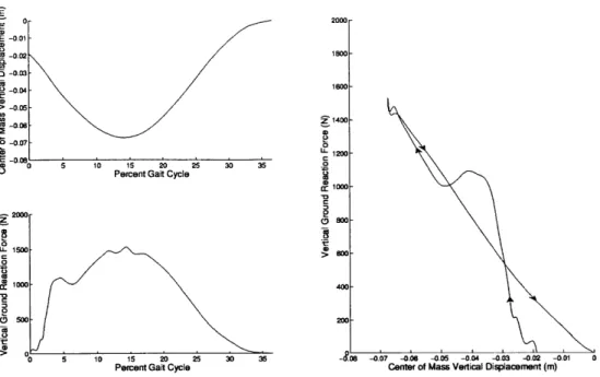
While walking resembles, and is most simply modeled as, an inverted pendulum with center of mass gravitational and kinetic energy oscillating out of phase, running most resembles a mass bouncing on a linear spring[33],[14][37]. Gravitational and kinetic energy remain primarily in phase in running while elastic energy stored in tendons contributes an out of phase component. In fact, the ground reaction force during stance phase varies approximately linearly with compression of effective leg length. Consequently, significant predictive power may be obtained from a simple spring-mass model which treats the body as a point spring-mass bounding on a constant stiffness spring[33].
Following convention, the gait cycle (depicted in Figure 4-3) begins at foot strike. During early stance phase, the leg's effective length (the distance from the center of mass to the ground) decreases as the knee flexes and the ankle dorsiflexes. During
E E -0.01 C. -00 o -0m .9 -0,04 > -0.05 Cc-0.06 -0. 07 2. 0 LL 1500 a: 1000 Soo50 5 10 1s 20 20
Percent Gait Cycle 30 35 -0.07 Center of Mass Vertical Displacement (m)-0.06 -0.05 -0.04 -0.03 -0.02 -001 0
Figure 1-4: Spring-like behavior of the leg in the vertical axis during running's stance phase, showing predominantly spring-like behavior. Effective leg length is measured from center of mass to ground during stance. The initial peak in vertical ground reaction forces is associated with impact effects. Data adapted from [151.
2 40 20 0 z ' -20 40 -40 O0 -.80 rz 0 Z r-0-100-LU 00 10o
o- Extension 20 30 40 Knee Angle (Degrees)s0 s0 70 so Flexion -90
Figure 1-5: Torque and angle of the knee during running. The knee behaves approx-imately as a clutched spring, exerting little torque during swing (from toe off to heel strike), but acting as a stiff spring during stance (from heel strike to toe off). Data adapted from [37].
5 10 15 20 25 30 35
Percent Gait Cycle
' '
~
-this time, the ground reaction force steadily increases[29][37] to three times body weight in distance running[36]. After midstance, when the body's center of mass is directly above the point of contact, this trend reverses; the leg extends while the ground reaction force decreases until the moment of toe off when swing phase begins. Swing phase, during which the leg is not in contact with the ground but is moving forward and preparing to support the body in a subsequent stance phase, follows toe-off and accounts for more than 60% of the gait cycle[37]. As swing phase typically occupies more than half of the gait cycle, an aerial phase exists during which both legs are in swing. In order to accelerate the leg forward as quickly as possible, a hip flexor moment approaching 200Nm[3] is applied while the leg's moment of inertia is simultaneously reduced by a large knee flexion. In terminal swing, the knee must again extend prior to foot strike.
As a result of its opposing roles in stance and swing, the leg can be thought of as a two stiffness system - nearly zero in swing and very stiff in stance. This may be observed directly in the torque-angle trajectory of the knee (Figure 1-5) and ankle, which resemble those of a clutched spring.
Following McMahon and Cheng[33], the elastic behavior of the full leg in stance phase may be modeled as a mass bounding on a so-called leg-spring, which connects the center of mass to the foot, as shown in Figure 1-3. First, consider the one dimen-sional problem of vertical displacement of center of mass. As shown in Figure 1-4 this displacement varies linearly with vertical ground reaction force, if a vertical spring supported the center of mass throughout stance. This effective spring is characterized by kvert, given by
kvert = Fzpeak (1.1)
Ay
where Fzpeak is the maximum vertical component of the ground reaction force and
Ay is the vertical displacement of the center of mass.
Due to the angle subtended, however, the effective leg spring in Figure 1-3, char-acterized by kieg, is compressed from its rest length LO by AL much larger than Ay,
16-14
-12
-4
E 10-I. 8- 4- 2-0 0 1 2 3 4 5 6 7Running Velocity (m/s)
Figure 1-6: The effective leg stiffness kie, depends weakly on running speed. Adapted from [14].
so that
ki eg - Fpa (1.2)
Assuming symmetry of absorptive and generative stance with 0 representing half the total subtended angle, it may be shown geometrically that AL is given by
AL = 6y + Lo (1 - cos0) (1.3)
Moreover, it can be shown [33] that the effective 0 is a function of forward velocity u and ground contact time tc:
0 = sin-
1(
j.)(1.4)
2Lo
kieg is used to characterize running gaits and must, by definition, be smaller than
kvert. For typical running speeds (3-5 m/s), the effective kieg is on the order of 10kN/m
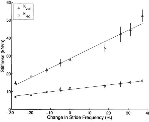
and varies relatively little with speed[33][14] as shown in Figure 1-6. Even with body weight supported in simulation of low gravity, leg stiffness does not change[22]. However, leg stiffness is not invariant; it does increase for instance if stride frequency
60-Skvert
5 k
leg
}
50-
40-E
c30-C
U)20-
10-0.-30
-20
-10
0
10
20
30
40
Change in Stride Frequency (%)
Figure 1-7: The effective leg stiffnesses kieg and k,,et increase with stride frequency. Adapted from [15].
is deliberately increased[15], as shown in Figure 1-7.
This spring-like dynamic of leg joints likely derives from passive energy storage, ac-counting for the efficiency of human running. Tendons and ligaments have been impli-cated in the energy transfer and storage observed during running stance phase[4] [1] [8], though it is important to note that even ideal energy storage of this kind is not with-out cost as the series muscle must exert an opposing force to enable tendon stretch. Even a nearly isometric contraction, yielding little or no net mechanical work incurs a significant metabolic cost[32][1].
(a) Unlocked and flexed, (b) Locked and extended, (c) Locked and compressed, offering minimal preparing for impact in storing energy in stance resistance in swing phase terminal swing phase phase
Figure 1-8: Conceptual behavior of a collapsable bow spring with exoskeletal knee joint, as used to augment running.
1.3
Augmentation of Hopping and Running
One may hypothesize that if the role of tendon could be fulfilled externally, series muscle activation could be reduced or eliminated while total kinetics, including the exoskeletal contribution, are preserved. In fact, there is evidence that total leg stiff-ness, including external contributions, is maintained in bounding gaits. If a series elasticity, namely a compliant ground surface, is introduced, total ket including the series compliant surface is maintained[18] [28], even when doing so requires increasing biological leg stiffness by up to 68%. This adaptation is extremely fast, occurring within the very first step after transition to the compliant surface[19]. In hopping, the presence of a parallel spring has been shown to reduce biological leg stiffness in order to achieve the necessary kvert, even when the external spring is non-linear[20]. An observed decrease in metabolic cost is hypothesized to be due to a decrease in activation of the ankle plantar flexors and knee extensors. Finally, if a passive spring is placed only across the ankle joint during hopping, total leg stiffness, kleg, and total ankle quasi-stiffness, including the exoskeletal contribution, are both similarly conserved[17]
This thesis investigates a modification to the hopping exoskeleton in which the bow spring may collapse at an exoskeletal knee joint during swing phase but subsequently
lock rigidly prior to stance, as shown conceptually in Figure 1-8. Such a device permits a normal swing phase while augmenting stance phase as the hopping exoskeleton does. In light of the limitations of past exoskeletons described in Section 1.1, the design of this exoskeleton focuses heavily on minimizing power consumption, mass, and the influence of the device on natural sensing and dynamics. Moreover, this architecture is robust in that it may be repurposed to span one or several joints of the leg.
This device is used to study the effects of parallel stiffness at the knee on human running. Specifically, the influences of such an external spring on total leg stiffness and individual joint stiffnesses are investigated using motion capture and inverse dynamics with healthy recreational runners.
The design of such a quasipassive running exoskeleton is described in this docu-ment in three parts:
" Human Attachment (Chapter 2): Attachment to the human body poses
both the functional question of which joints should be spanned by the parallel elastic element and the pragmetic question of how an elastic element may be fixed to the body in order to safely and comfortably transfer load.
" Mechanical Design (Chapter 3): Commercially available clutches capable
of locking the spring and withstanding load during stance phase are far too heavy to be comfortably attached to the leg during running, necessitating the development of a custom high-torque clutch.
" Control (Chapter 4): Locking and unlocking the parallel spring requires
precise timing and high reliability and ideally is performed using only intrinsic sensing at the exoskeletal knee.
Subsequently, in Clinical Testing and Results (Chapter 5), the results of an experiment investigating the kinematic effects of parallel stiffness applied to the human knee in running are presented. Finally, Discussion (Chapter 6) considers the consequences of this work, both to biomechanics and to the future of mechanical interventions.
Chapter 2
Human Attachment
Load-bearing attachment to the human body poses several problems. First, there is a question of which joints the exoskeleton's springs should span. Subsequently, the problem of attachment itself is made particularly daunting by the compressibility of soft tissue and the ability of skin to translate relative to the underlying skeleton during motion.
2.1
Joint Geometry
The device described in this thesis constitutes a platform by which parallel elasticity may be applied to one or several joints of the leg, depending on the choice of harness. In principle, a harness needs simply to connect the body's center of mass to the ground through the passive compliance offered by the exoskeleton, but any number of geometries may accomplish this goal. Since all devices of this type span the knee, energy is stored during early stance knee flexion and returned during late stance extension. Energy storage due to motion in other joints depends on our choice of architecture and, in particular, whether the proximal attachment of the spring spans the hip and whether the distal attachment spans the ankle. Figure 2-1 schematically depicts the several exoskeleton geometries.
Though the experiment presented in Chapter 5 uses configuration (a), spanning only the knee, it is worthy of mention that configurations (b), (c), and (e) have been
Not Spanning the Ankle
(a)
Spanning the Ankle
(b)
Spanning Ankle and Foot-Ground Interface
(c)
Figure 2-1: Possible configurations of the clutched parallel elastic exoskeleton by
combination of exemplary proximal and distal attachments from Figures 2-2 and 2-3.
Though shown with anterior spring orientation, posterior orientation is also possible.
Configuration (a) is ultimately investigated here.
built and tested to varying degrees. Configuration (b), which spans the ankle and knee, corresponds to the hopping exoskeleton from which this works evolved (though the original harness may in practice permit very small moment arms about the hip). Unfortunately, the rigid toe attachment is better suited to hopping than to running, as it requires forefoot striking, thereby dramatically changing gait, and the mass of the device must be borne by the ankle during swing, thereby significantly increasing metabolic demand. Configuration (c) introduces a center of pressure tracking foot attachment to address the former problem and permit heel or midfoot striking, but this attachment point is complicated and prone to failure. Finally, configurations such as (e), with significant moment arms about the hip require a chest harness, which has proven significantly less comfortable than a cuff around the thigh in extended use.
If the spring spans the hip, a harness may be designed so that energy is stored during hip flexion and returned during hip extension. Because the torso remains nearly upright, an attachment around the pelvis (Figure 2-2c) like the rigid harness used in earlier hopping experiments or to the chest (Figure 2-2d) may be used to provide small or large moment arms about the hip. Alternatively, a pelvic harness aligned with the center of hip rotation (Figure 2-2b) minimizes this moment arm and attaching distal to the hip, as by compressive cuffs around the thigh (Figure 2-2a), eliminates hip involvement.
The ankle joint is more complicated. The conceptually simplest distal attachments are those in which attachment occurs above the ankle, as in Figure 2-3a. In these designs, rotation of the ankle does not affect spring compression. However, loads cannot be transferred directly into the ground; they must be transferred through the human skeleton. Even in the absence of ankle involvement, a single degree of freedom is still necessary at the attachment of the spring to accommodate rotation of the spring end due to bowing. A simple plain bearing permitting rotation in the sagittal plane suffices. Construction of these designs proves difficult due to migration and the inability to compress the calf without affecting the gastrocnemius and soleus. As with the pelvic compression harness, it is possible to approximate an above the ankle design by loading to the ground through an offset point nearly concentric with the
ankle as in Figure 2-3b, but in practice it is difficult to build such a structure into a shoe with sufficient rigidity. It is simpler to attach to knee or ankle braces, also shown in Figure 2-3a, to prevent migration.
If ankle involvement is desired, an attachment point may be placed near the ball
of the foot, as in Figure 2-3c so that ankle dorsiflexion causes compression of the spring during early stance. A single degree of freedom is still sufficient, as it permits both ankle motion and bowing of the spring. For practical construction, this joint may be rigidly attached to the the toe cleat of a biking shoe, as it was in hopping exoskeleton. Ankle spanning of this sort assumes that the user toe runs, striking and leaving the ground on the ball of the foot. Unfortunately, as most runners do not naturally toe-strike as prominently as this design requires, ankle plantar flexors tend to fatigue quickly while wearing this harness. Additionally, the rigid sole and metal plate at the cleat proves uncomfortable for some users. Ideally, an attachment to the foot which spans the ankle should account for natural heel or mid-foot strikes followed by anterior motion of the center of pressure leading up to toe off on the ball of the foot. Such an attachment point may be thought of as spanning both the ankle and the foot-ground interface. One way of constructing such a device is depicted schematically in Figure 2-3d.
2.2
Harness Evolution
The harness used for the exoskeleton has evolved significantly over its development, originally spanning the knee and ankle and eventually only spanning the knee.
The original harness, shown in Figure 2-4a, is nearly identical to the harness developed for a hopping exoskeleton. A rigid proximal frame is attached to the waist and groin using a standard climbing harness while the structure is compressed against the pelvis, as in Figure 2-2b. A three degree-of-freedom joint concentric to the hip offers full range of motion of the exoskeletal spring, which attaches distally to a one degree-of-freedom joint lateral to the toe of a shoe, as in Figure 2-3c. Unfortunately, this design assumes the symmetrical loading found in hopping and tends to rotate in
(a) Molded cuffs compress the thighs, likely elastically supported by the opposing hips and potentially part of a full knee brace. Care is taken to avoid compressing the
hamstrings. Attachment is typically lateral (shown); anterior and posterior attachments are possible but uncomfortable and unwieldy.
(b) A rigid frame compresses the pelvis and is anchored by a climbing harness around the legs. Attachment is lateral and approximately aligned with the greater trochanter. As such, it is approximately concentric to the hip and may be considered as not spanning the joint. This harness was used with in the hopping exoskeleton.
(c) The pelvis compressing frame in (b) is used with attachment points located significantly above the hip. Attachment is typically lateral (shown) or posterior;
o anterior attachment is possible but unwieldy.
ci-4
(d) A molded cuff compresses the chest with shoulder straps to minimize migration. Load may also be shared with thigh cuffs (right). Attachment is anterior or posterior.
Figure 2-2: Three possible attachments for the proximal end of the bow spring. Some
designs allow the spring to span the hip joint, while others eliminate hip involvement.
A single sagittal plane rotation joint indicated by a dark circle permits flexion of the
(a) Molded cuff compresses the calf, likely integrated into a full knee or ankle brace (shown, right) to reduce migration.
(b) Rigid attachment to the heel, offset to be approximately concentric to the ankle.
(c) Rigid attachment at the toe. Forces toe running. This attachment was used in the hopping exoskeleton.
(d) An additional two degrees of freedom (one rotational, one linear) permit direct ground contact independently of foot position, allowing normal heel strike and toe off while loading directly into the ground.
Figure 2-3: Four possible attachments for the distal end of the bow spring. Some designs allow the spring to span the ankle joint, while others eliminate ankle in-volvement. A single sagittal plane rotation joint indicated by a dark circle permits flexion of the bow spring in all cases. Attachments are shown configured for lateral attachment, but may also be used for anterior or posterior attachment.
C12
(a) Pelvic harness with toe attachment
(c) Thigh cuff harness with shank attachment
(b) Thigh cuff harness with toe attachment
(d) Knee brace harness
the coronal plane when loaded unilaterally, making it poor at loading the exoskeletal spring. This harness is also heavy and somewhat uncomfortable to wear and the mass of the exoskeleton must be borne through the ankle in swing, making it very costly metabolically.
An alternate proximal harness, shown in Figure 2-4b, loads through molded thigh cuffs as in Figure 2-2a. This design offers greater hip mobility, less discomfort, and a significantly reduced mass. Most importantly, the proximal attachment point is far less able to move up the leg under load, improving energy storage in the spring.
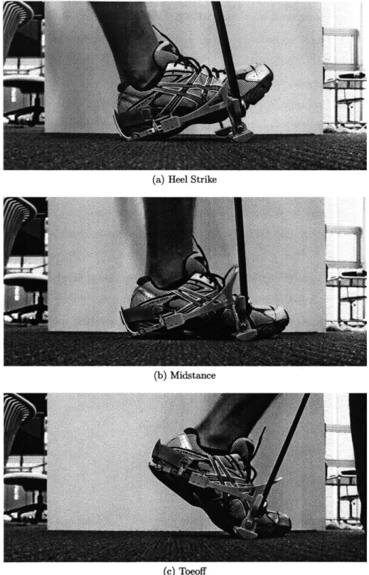
Loading the spring propertly using a distal attachment rigidly connected to the toe requires a plantar flexed toe-striking gait which is not natural for most runners. One solution to this problem, shown in Figure 2-5, is an articulated distal attachment which allows the spring to load through the ground even as the foot moves around it. At heel strike, the spring contacts the ground below the toe. As the foot rolls forward, the linear and rotary joints allow the spring contact point to remain stationary until toe off, after which return springs reset the device. This design requires manual tuning of two degrees of freedom to match the wearer's foot size and foot angle at heel-strike. It also increases leg length slightly, potentially causing ground interference in late swing. Ultimately, without full integration into a shoe, this attachment proved too complex and fragile for practical use.
Alternatively, the problem of ankle articulation can be avoided by not spanning the ankle. An alternative distal harness, shown in Figure 2-4c, attaches the exoskele-ton to the shank, loading to the ground through a stirrip, as in Figure 2-3a. This additionally solves the problem of supporting the exoskeletal mass through the ankle during swing. Unfortunately, a satisfactory ankle joint was never achieved. Those which were attempted either proved uncomfortably heavy or failed under load.
This knee-spanning architecture can be achieved using a harness similar to a traditional polycentric knee brace with elements borrowed from prosthetic socket technology, shown in Figure 2-4d. On either side of the knee, the exoskeleton attaches to the leg using rubber-lined carbon fiber cuffs molded to one wearer. Care has been taken to remove material from the cuffs in areas where muscle bellies may protrude,
(a) Heel Strike
(b) Midstance
(c) Toeoff
Figure 2-5: An articulated distal attachment which spans both the ankle and the
foot-ground interface.
most notably around the hamstrings and gastroenemius. Rigid carbon fiber strips back the brace at its most proximal and distal extents and independently adjustable velcro straps secure the brace to the leg both anterior and posterior at four heights (two proximal and two distal). The brace may be padded to improve fit when worn
by other than the cast subject.
The exoskeletal springs are attached laterally to the thigh cuffs. Lateral mounting has the advantage of allowing the springs to follow the form of the leg relatively closely, but the disadvantage that it widens the wearer and produces a larger than normal torque about the center of mass during stance. For these reasons, efforts have been made to reduce the lateral displacement of the exoskeleton as much as possible.
The experiment presented in Chapter 5 considers this knee brace harness, corre-sponding to configuration (a) in Figure 2-1. For this purpose, spanning only the knee is adventageous in that it facilitates biomechanical analysis of the exoskeleton's ef-fects on a single joint. Pragmatically, this configuration also holds particular promise as a practical orthosis. One may hypothesize that, during running, a robotic knee brace built in this way could reduce load and therefore pain for sufferers of chronic knee pain. Such a device could even permit recreational running in patients currently forced to avoid high impact activities.
Chapter 3
Mechanical Design
An exoskeletal knee joint that permits running is difficult to build. The human knee experiences torques which may reach 200Nm during stance phase of running. Assum-ing that the exoskeleton geometry is similar to that of the natural leg, the proposed exoskeletal knee joint should be rated to loads of at least this in order to permit any of the various attachment configurations described in Chapter 2. In practice, the natural leg will still bear some fraction of this load, rendering this rating conserva-tive. The exoskeletal knee must lock precisely at peak knee extension, immediately before the swing phase retraction which precedes foot strike, to ensure that the spring begins deforming immediately at foot strike and maximum energy is stored. Conse-quently, the device must offer a high resolution of potential locking angles (or ideally a continuum) and must be capable of engaging quickly. Latency compensation (see Section 4.2.2) proves reliable at accurately predicting peak extension up to 50ms in advance, so the device must be capable of locking within that window. Finally, due to the high metabolic demand of forward swing and the corresponding necessity for a low moment of inertia about the hip, the joint must permit large knee flexion up to 1350
and contribute as little distal mass to the leg as possible. These design specifications are enumerated in Table 3-1.
Due to the large number of components and relative complexity of this design, notation can become troublesome. The following convention is used. If it is neces-sary to disambiguate the component or subassembly being discussed, a single letter
Symbol Description Goal Achieved
T Holding Torque 200 Nm 190 Nm
Fr Radial Load 3,000 N 4,780 N
Fa Axial Load 1,000 N 4,050 N
Ateng Engagement Time 50 ms 26 ms
Resolution 2 * 1.8 0
Range of Motion 135 0 1300
Mass 1,000 g 710 g
Diameter 100 mm 85 mm
Thickness 50 mm 49 mm
Table 3-1: Design specifications for the exoskeletal knee clutch. As the clutch has not been driven to failure, its maximum load capacities are estimated.
Component Subscript Clutch Subassembly c Transmission Subassembly t Ring Gear r Planet Gear p Sun Gear s
Sun Gear Rim h
Clutch Plate p
Linear Bearing 1
Elastic Element e
Brace b
Table 3-2: Subscripts used to disambiguate the component referenced, listed in order of appearance.
or subassembly being
subscript is used. If the symbol in question were to normally contain a subscript, the component subscript will follow it, with a comma separating the two. The subscripts used are summarized in Table 3-2. A similar convention is used for materials, as shown in Table 3-6. Modifiers such as min and max will follow all other subscripts, again preceded by a comma.
3.1
Exoskeletal Knee
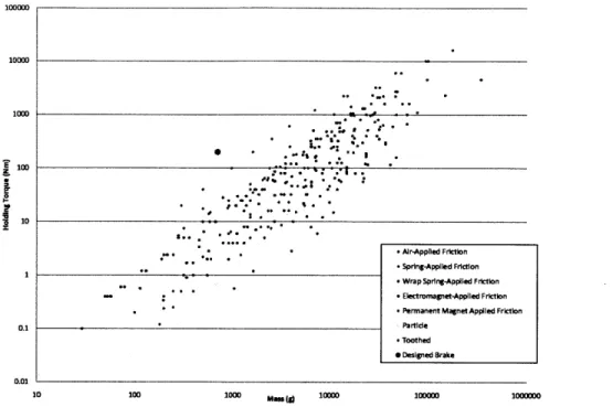
No commercially available clutch or brake is suitable for these specifications. Consider the available technologies:
" Particle brakes use an electromagnet to bind together a ferrous powder,
im-peding the motion of a brake rotor through it. Particle brakes permit very accurate control of torque, which varies almost linearly with applied voltage.
" Friction clutches force two surfaces against each other, using the friction
between them to prevent slippage. A sufficient normal force must be applied in order for the clutch to remain locked. This force may be provided by air pressure, springs, or permanent or electro-magnets. The wrap spring clutch is a unique friction clutch in which positive feedback exists between applied torque and the frictional force engaging the clutch.
" Toothed clutches are similar to friction clutches, but use disks with
inter-locking tooth structures instead of relying purely on friction. Toothed clutches may withstand significant torque, but at the cost of discretizing the possible engagement angles. In some cases a synchronizer is necessary to ensure that the toothed disks do not begin to engage at other than an allowed engagement angle.
Of these options, toothed clutches offer by far the highest holding torque for a
given volume, as load is shared over all teeth, producing a large shear area of resis-tance. Unfortunately, as shown in Figure 3-1, even the lightest commercially available device offering sufficient holding torque for our application has an unacceptably high mass of 1.6kg. Equally troubling, toothed clutches offer only discretized engagement angles with poor resolution (50 is typical). As a result, it proved necessary to design a custom toothed clutch with an integrated planetary gearbox which decreases load on the clutch plates and increases effective resolution. The complete device, depicted schematically in Figure 3-2, is constructed so that the distal bow spring attachment serves as input to the ring of a planetary system whose planet carrier is fixed to the proximal assembly. The output of the planetary system (the sun) is coupled through a toothed clutch to the proximal assembly, effectively locking the joint when the clutch is engaged by activation of the solenoid.
100000 10000 1000 * .. . a e .
r
j 10 *. * .Air-Applied Friction - Spring-Applied Friction 1 Wrap SprIng-Applied Friction* .. Electromagnet-ApplIed Friction
-Permanent Magnet Applied Friction
0.1 Partide
-Toothed .Designed Brake 0.01
10 100 1000 Mass(g 10000 100000 1000000
Figure 3-1: Maximum holding torque versus mass plotted on log-log axes for several hundred commercially available clutches and brakes. For comparison, the exoskeletal knee described here is also shown, plotted with a mass which additionally includes electronics, instrumentation, and mounting.
The complete exoskeletal knee is intended to be as light as possible in a package comparable in size to the human knee with no medial protrusions. As inertia in the distal portion is detrimental to rapid knee flexion, the majority of mass should be located in the proximal subassembly. To reduce and facilitate maintenance, efforts should be made to minimize internal wiring. Finally, to simplify manufacturing and encourage the production of spare parts, as many parts as possible should be achiral. The self-contained electromechanical system, shown in Figures 3-3 and 3-4, includes mounting, power supply, and electronics and withstands a 200Nm load while fitting in an 85mm diameter by 49mm thick package with a mass of only 710g.
3.1.1
Clutch
At the heart of the mechanism is the toothed clutch, which selectively couples the output of the planetary gearbox rigidly to the proximal assembly. One clutch plate therefore rotates with the planetary sun and is coupled by gearing to the distal
attach-Optical _ncoder
1:2.2
Planetary
Gearbox
\61
E
4*
Dog
Clutch
Figure 3-2: Schematic depiction of the designed clutch, showing the dog clutch,
in-tegrated planetary gearbox, and instrumentation. The system, including the orbit of
the planetary gearbox, is depicted as mechanically grounded to the proximal
assem-bly. Note that though the actual device is functionally equivalent to this depiction,
its construction varies significantly.
Symbol
Description
Value
Nc
Clutch Plate Tooth Count
90
he
Clutch Plate Tooth Height
2.0 mm
we
Clutch Plate Tooth Width
1.5 mm
de
Clutch Plate Tooth Depth
6.5 mm
ri,c
Clutch Plate Tooth Inner Radius
22.5 mm
roc
Clutch Plate Tooth Outer Radius
29.0 mm
rb,c
Clutch Plate Coupling Boss Radius
16.0 mm
tc
Clutch Plate Thickness
1.5 mm
(a) Fully assembled (b) Latteral assembly removed to show encoder disk, solenoid, and solenoid mount
(c) Lateral planet carrier removed to show (d) Medial planet carrier and translating planetary gearbox clutch plate removed to show rotating
clutch plate
(e) Reverse angle with medial components removed to show both clutch plates in the disengaged state
No. Name Material Mass (g) Quantity
1 Rotating Clutch Plate (Right) Titanium Grade 2 28.6 1
2 Translating Clutch Plate (Right) Titanium Grade 5 18.7 1
3 Sun Gear Titanium Grade 5 22.5 1
4 Ring Gear Titanium Grade 5 48.9 1
5 Planet Gear Titanium Grade 2 8.3 3
6 Long Planet Gear Titanium Grade 2 9.9 1
7 Pin Titanium Grade 2 0.9 2
8 Medial Planet Carrier Aluminum 6061 49.5 1
9 Lateral Planet Carrier Aluminum 6061 57.8 1
10 Hard Stop Aluminum 6061 2.2 1
11 Solenoid Mount Aluminum 6061 8.6 1
12 Lateral Cap Aluminum 6061 38.1 1
13 Medial Cap Aluminum 6061 6.5 1
14 Distal Ear Aluminum 6061 20.3 2
15 Proximal Mount Aluminum 6061 32.6 1
16 Distal Mount Aluminum 6061 36.6 1
17 Circuit Board (Multiple) 25.0 1
18 Lithium Polymer Battery (Multiple) 16.8 1
19 Light Pipe Acrylic 0.0 16
20 Right Angle Light Pipe Acrylic 0.2 1
21 EP4 Optical Encoder Disk Aluminum 6061 3.0 1
22 LT8x9 Solenoid Brass and Copper 55.0 1
23 Solenoid Plunger Ductile Iron 22.6 1
24 Solenoid Return Spring Steel 0.2 1
25 Sun Bearing Steel AIS1304 20.0 2
26 Ring Bearing Steel AIS1304 56.8 2
27 Planet Bearing Bronze SAE841 0.5 8
28 Retaining Ring Cast Carbon Steel 3.7 1
29 E-Clip Cast Carbon Steel 0.2 1
30 M1.6x0.35x4 Cap Screw Steel 0.5 2
31 M2xO.4x4 Cap Screw Steel 0.3 2
32 M2xO.4x8 Cap Screw Steel 0.4 2
33 M2.5x.45x8 Cap Screw Steel 0.7 4
34 M3xO.5x6 Flat Head Screw Steel 0.5 1
35 M3xO.5x8 Flat Head Screw Steel 0.6 4
36 M3xO.5x20 Flat Head Screw Steel 1.4 2
37 M4xO.7x6 Cap Screw Steel 1.2 8
38 M4xO.7x16 Cap Screw Steel 2.3 4
Figure
its bill
3-4: The right knee clutch at 1:5 scale shown assembled and exploded with
of materials. The first 17 entries in the bill of materials are custom made;
the remainder are available off the shelf. The device is oriented as one would face a
wearer, so that the lateral direction is to the left of the drawing. The clutch plates
(Section 3.1.1) are to the far right and the planetary gearbox (Section 3.1.2) is in the
center. The left knee clutch varies only in the orientation of the proximal and distal
mounts, the initial orientation of the sun gear relative to the hard stop, and the use
of left-handed dog clutch plates.
Figure 3-5: The translating clutch plate shown actual size with a detail 4:1 view of the sawtooth geometry.
ment while the other is constrained only to translate axially relative to the proximal assembly and is driven by a solenoid to engage the rotating plate.
To avoid the need for a synchronizer, the sawtooth dog clutch (Figure 3-5), is preferred to the square tooth castle clutch. The dog topology ensures that during partial engagement an energy gradient exists which tends to align and fully engage the clutch. To minimize wear, the sharp roots and tips of the teeth are filleted. Unfortunately, this also introduces an unengaged unstable equilibrium, but in practice any movement of the device remedies this potential problem.
The choice of a dog clutch also permits a ratcheting effect; when engaged, the joint cannot be flexed, but extension remains possible. Consequently, control strategies may err in favor of early engagement before the knee has reached peak extension. Deliberately doing so is not a reasonable strategy, however. Extension of the joint during clutch engagement is somewhat impeded and presumably contributes a non-negligible metabolic cost.
The clutch plates are produced in titanium to minimize weight and two differ-ent alloys (grades 2 and 5) are used to reduce galling. The geometry of the clutch plates is heavily constrained by tight integration with the planetary gearbox (see