HAL Id: hal-01063335
https://hal.archives-ouvertes.fr/hal-01063335
Submitted on 11 Sep 2014
HAL is a multi-disciplinary open access
archive for the deposit and dissemination of
sci-entific research documents, whether they are
pub-lished or not. The documents may come from
teaching and research institutions in France or
abroad, or from public or private research centers.
L’archive ouverte pluridisciplinaire HAL, est
destinée au dépôt et à la diffusion de documents
scientifiques de niveau recherche, publiés ou non,
émanant des établissements d’enseignement et de
recherche français ou étrangers, des laboratoires
publics ou privés.
Method for vector sensor design based on a spherical
mode approach for 3D DoA estimation
Jimmy Lominé, Christophe Morlaas, Hervé Aubert
To cite this version:
Jimmy Lominé, Christophe Morlaas, Hervé Aubert. Method for vector sensor design based on a
spherical mode approach for 3D DoA estimation. European Conference on Antennas and Propagation,
Apr 2013, Gothenburg, Sweden. 5p. �hal-01063335�
Method for vector sensor design based on a
spherical mode approach for 3D DoA estimation
Jimmy Lominé
∗†, Christophe Morlaas
†, and Hervé Aubert
‡∗Rockwell Collins France, 6 av. Didier Daurat, B.P. 20008, 31701 Blagnac, France, Email: jlomine@rockwellcollins.com †ENAC / TELECOM EMA, 7 av. E. Belin, 31055 Toulouse, France, Email: morlaas@recherche.enac.fr
‡University of Toulouse ; UPS, INSA, INP, ISAE ; LAAS ;
7 av. du colonel Roche, F-31077 Toulouse, France, Email: haubert@laas.fr
Abstract—A design process for the rapid determination of
an efficient vector sensor configuration is presented. The vector sensor is applied to the 3D direction finding based on a spherical mode approach. A criterion of the estimation efficiency has been established allowing to predict the trend of the estimation errors of 3D direction of arrival in presence of perturbations caused by the coupling effects and the surrounding perturbations. The direction finding accuracy is evaluated with this method for several spatial distributions of 6 theoretical antenna elements and for a more realistic sensor with 3 antenna elements.
Index Terms—vector sensor; 3D direction of arrival finding ;
spherical mode; efficiency criterion
I. INTRODUCTION
To determine the direction of arrival (DoA) of incoming electromagnetic signals, two parameters can be used: the spatial diversity and/or the polarization diversity. The major part of direction finding algorithms uses the spatial diversity such as interferometry which extracts the phase differential between each radiating element of the direction finding antenna in order to compute the DoA. It can be applied for 3D direction finding but the antenna design becomes too complex and cumbersome to compute the DoA in all space. The use of the polarization diversity has the advantage to require smaller sensor size. The DoA is estimated through the components measurement of the incoming electromagnetic field. It can be performed with 6 co-located antennas [1]. For instance, a combination of 3 elementary orthogonal electric dipoles and 3 elementary orthogonal magnetic dipoles can measure the six components of the electromagnetic field [2]. Generally, to reduce the coupling effects, a spatial separation of antenna elements can be applied. A method has been proposed to estimate the DoA with a vector sensor with distributed elements using a spherical mode approach [3]. For co-located antenna elements, only the 6 first spherical harmonics are necessary. But when a spatial separation is applied between antenna elements, higher order spherical modes radiate and thus the DoA estimation with only 6 antenna elements becomes inaccurate.
In this article, a criterion is firstly introduced to evaluate the DoA estimation efficiency. Secondly, with a vector sensor of 6 theoretical elements, the efficiency criterion is related to
the accuracy of the DoA according to the spatial distribution of the antenna elements. Thus it allows a rapid determination of estimation performances trend. Finally, the previous results lead to study a vector sensor composed of 3 co-located elements by considering the radiation perturbations by means of a full wave electromagnetic simulation (FEKO). The aim of these numerical experimentations is to check that the efficiency criterion considers the effects of the radiation pertubations on the DoA accuracy. To achieve it, different configurations of the realistic antenna are simulated: one with an infinite metallic plate and others with a finite plate of different sizes.
II. PRINCIPLE
The number of significant spherical harmonics for accurate estimation can be related to the number of antenna elements [4]. But when the number of relevant spherical modes becomes higher than the𝑁𝑎antenna elements due to a spatial separation applied to antenna elements or radiation perturbations, the DoA estimation becomes inaccurate. Thus it is important to evaluate the trend of the DoA estimation performances according to different vector sensor configurations and to the surrounding perturbations.
A. DoA estimation
According to the method presented by Chabory et al. [3], the Poynting vector ⃗𝑃 (1) can be estimated from an inversion process (2) between the spherical harmonic decomposition of the outgoing electromagnetic fields and the incoming elec-tromagnetic field computed at the center of sensor from the spherical harmonic recomposition.
⃗𝑃 = 12𝑅𝑒{ ⃗𝐸0∧ ⃗𝐻0∗} (1) [ ⃗𝐸0 ⃗ 𝐻0 ] =[ 𝑒𝑠− 0 , ℎ𝑠−0 ] (𝑀+𝑇)−1𝐴− (2)
with ( ⃗𝐸0, ⃗𝐻0) the recomposed electromagnetic field at the center of the sensor, (𝑒𝑠−0 , ℎ𝑠−0 ) the electromagnetic fields at the center of the sensor of incoming spherical harmonics,𝐴− the vector of the wave amplitudes received at the antenna ports and 𝑀+ the matrix of the coefficients associated with the
outgoing spherical harmonics 𝑠+𝑚,𝑛 [5], with 𝑚 the azimuth index and𝑛 the elevation index.
𝑛 ∈ [1, ..., 𝑁𝑠] 𝑚 ∈ [−𝑁𝑠, ..., 𝑁𝑠] (3)
where 𝑁𝑠is the spherical mode order.
B. Criterion of the estimation efficiency
Thanks to the reaction theorem, the knowledge of 𝑀+ allows to predict the trend of the DoA estimation performances of a vector sensor. An efficiency criterion𝜂𝑒 (5) is introduced from the singular values of 𝑀+ (4). Thus coupling effects and the surrounding perturbations for a realistic antenna can be considered. 𝑀+= 𝑈Σ𝑉 =[𝑢 1 . . . 𝑢𝑁𝑠 ] ⎡ ⎢ ⎣ 𝜎1 0 . .. 0 𝜎𝑁𝑎 ⎤ ⎥ ⎦ ⎡ ⎢ ⎣ 𝑣1 .. . 𝑣𝑁𝑠 ⎤ ⎥ ⎦ (4) where 𝑢𝑖 and𝑣𝑖 correspond to the𝑖-th left and right singular vectors respectively, and 𝜎1 ⩾ 𝜎2 ⩾ . . . ⩾ 𝜎𝑁𝑎 are the singular values of𝑀+.
𝜂𝑒 = 𝑐𝑜𝑛𝑑(Σ)¯Σ (5)
where ¯Σ and 𝑐𝑜𝑛𝑑(Σ) are the average of the singular values of 𝑀+ and its condition number respectively. To normalize the criterion𝜂𝑒 according to another antenna configuration, a reference criterion of the estimation efficiency 𝜂𝑒𝑅𝑒𝑓 can be used (6).
𝜂𝑒𝑁 = 𝜂𝑒
𝜂𝑒𝑅𝑒𝑓 (6)
III. SIX DISTRIBUTED ANTENNA ELEMENTS
(a) (b) (c)
(d)
Fig. 1: Simulated antenna configurations with 3 elementary orthogonal electric dipoles and 3 elementary orthogonal mag-netic dipoles.
Four geometrical configurations which are represented in Fig. 1 have been simulated. Each one is a combination of 3 elementary orthogonal electric dipoles and 3 elementary orthogonal magnetic dipoles spatially distributed. The ele-mentary magnetic dipoles are considered from eleele-mentary electric loops. No coupling effects between antenna elements is considered. The reference configuration is the six co-located antenna elements. It is the ideal case with the spherical mode
approach. The vector sensor performances are analyzed from the angular distance of the estimation error Δ𝑎 between estimated and real DoA as defined in (7).
Δ𝑎 = cos−1(cos(𝜃
𝑟) cos(𝜃𝑒) + sin(𝜃𝑟) sin(𝜃𝑒) cos(𝜙𝑟− 𝜙𝑒))
(7) where(𝜙𝑟, 𝜃𝑟) are the coordinates of the real DoA and (𝜙𝑒, 𝜃𝑒) are the coordinates of estimated DoA. In Fig. 2 and in Fig.
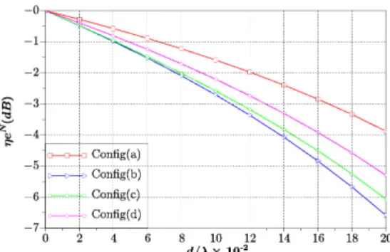
Fig. 2: Efficiency of DoA estimation normalized with respect to the co-located configuration.
Fig. 3: Maximum DoA estimation error -(Δ𝑎)𝑚𝑎𝑥. 3 the estimation efficiency (𝜂𝑒) and the estimation error (Δ𝑎) are displayed according to the normalized separation distance
𝑑/𝜆 for the 3 antenna configurations represented in Fig. 1,
with 𝜆 the wavelength. The incident plane waves have a circular polarization. The estimation error corresponds to the maximum estimation error in full 3D space. The criterion 𝜂𝑒 decreases according to the distance 𝑑/𝜆 due to the radiation of the higher order spherical modes and follows the behavior of the error estimation. The less the efficiency, the more the maximum DoA error. The most efficient sensor is the antenna configuration(𝑎) in Fig. 1. The ratio of the computation time between the simulation of the maximum DoA error and the computation of the estimation efficiency is 17 for an angular resolution of 1∘. Thus it allows a rapid determination of the best antenna configuration.
IV. THREE CO-LOCATED ANTENNA ELEMENTS-{EZ, HX, HY}
The previous study of the efficiency criterion according to only the separation distance between antenna elements has shown that a lower distance of separation yields better performances. But the spatial distribution is not the only cause of DoA estimation errors. Indeed the coupling effects and the
surrounding perturbations can disturb the radiation pattern of the antenna and so the direction finding accuracy. To check that these perturbations are taken into account through the efficiency criterion, a vector sensor of 3 co-located antenna elements is modeled. Only the half-space domain is considered by using a metallic plate (Fig. 4) in the aim of an easier manufacturing and to ensure a good reproducibility of DoA estimation whatever the antenna support. Full wave simulations are performed to take into account realistic antennas with the coupling effects and the metallic plate. Several antenna configurations are simulated in order to have a comparative study: one with an infinite plate and others with a finite plate with different sizes. The components of the electromagnetic field{Ex, Ey, Hz} are shorted due to the metallic plate at the center of the sensor. That’s why only incident plane waves in TM mode have been simulated.
Fig. 4: Antenna configuration -{Ez, Hx, Hy}.
A. Adaptation of the DoA algorithm
The DoA algorithm must be adapted to a sensor of 3 antenna elements by judiciously selecting the relevant spherical harmonics in 𝑀+. Indeed, with this spherical mode approach, only 𝑁𝑎 spherical harmonics can be used to recompose the field at the center of the sensor.
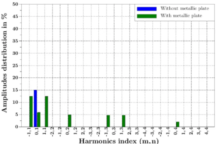
Moreover the infinite metallic plate modifies the amplitudes distribution of the outgoing spherical harmonics coefficients as shown in Fig. 5 and in Fig. 6. Without metallic plate,
Fig. 5: Theoretical amplitudes distribution of the outgoing spherical harmonics coefficients associated with the electric field without (blue) and with (green) an infinite plate. only the first spherical mode radiates, 𝑁𝑠 = 1. But with a plate, some higher spherical modes radiate. These higher
Fig. 6: Theoretical amplitudes distribution of the outgoing spherical harmonics coefficients associated with the magnetic field without (blue) and with (green) an infinite plate.
spherical harmonics allow only to cancel the electromagnetic field in the directions below the plate by combination with the fundamental mode. These modes are not necessary to recompose the electric and magnetic field [ ⃗𝐸0, ⃗𝐻0] from the incoming waves received in the upper half-space domain. Thus𝑀+is adjusted by conserving the coefficients associated with the outgoing spherical harmonics 𝑠+−1,1 and 𝑠+1,1 of the magnetic field and 𝑠+0,1 of the electric field.
Moreover the Poynting vector computation can not be performed without all field components. The DoA computation must be also adapted as defined in (8).
𝜃 = sin−1 ⎛ ⎝√ ∣𝐸𝑧∣ (𝐻2 𝑥+ 𝐻𝑦2)𝜁 ⎞ ⎠ 𝜙 = tan−1(𝐻𝑦 𝐻𝑥 ) (8)
with𝜁 the wave impedance.
This adjustment of 𝑀+ has been validated by numerical simulations for elementary dipoles with an infinite metallic plate. No DoA error is generated by removing these higher spherical modes because all necessary information for an accurate DoA estimation are carried by the first spherical mode. This antenne will be the reference for the following study.
B. Realistic antenna design
The realistic vector sensor, represented in Fig. 7, is com-posed of two orthogonal and horizontal magnetic dipoles and a virtual vertical electric dipoles resulting from the combination of the two loops response by setting [1, 1, 1, 1] to the four ports. The operating frequency is set to 1GHz.
C. Full wave simulations
The purpose of these simulations is to check that the computation of the efficiency criterion takes into account the radiation perturbations and the metallic plate effect on the
Fig. 7: Simulated antenna with a full wave electromagnetic simulation software.
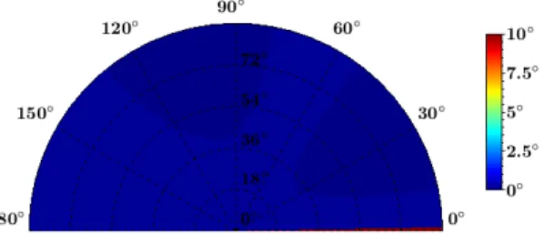
DoA accuracy. The fields radiated by the realistic antenna elements and simulated from full wave electromagnetic simulations are thus used to compute 𝑀+. Only the half of the upper half-space domain is simulated because there is a symmetry in the results between [0 − 180∘] and [180 − 360∘] azimuth angles. The reference configuration used to normalize the criterion of the estimation efficiency is the theoretical sensor{Ez, Hx, Hy} with an infinite metallic plate previously studied in part IV-A. For each simulation, the DoA accuracy is computed separately for the azimuth and the elevation angles as shown for two configurations in Fig. 8 to 11. Then for each one, the efficiency criterion is computed and compared to the DoA estimation accuracy as illustrated in Table I. The
Fig. 8: DoA estimation error in elevation with an infinite metallic plate.
Fig. 9: DoA estimation error in azimuth with an infinite metallic plate.
trend of DoA accuracy is well evaluated with the criterion of the estimation efficiency. It shows that the direction finding performances are sensitive to the size of the metallic plate. Indeed, the larger the plate, the better the estimation accuracy.
However with the infinite metallic plate the DoA error is de-graded in comparison to the theoretical case with a maximum
Fig. 10: DoA estimation error in elevation with a finite metallic plate of 1.5𝜆.
Fig. 11: DoA estimation error in azimuth with a finite metallic plate of 1.5𝜆.
error of 12∘ in elevation. This DoA error is caused by the realistic antennas which generate radiation patterns different to elementary dipoles. This difference can be observed in the amplitudes distribution of the outgoing spherical harmonics coefficients for both configurations as shown in Fig. 12 and in Fig. 13. The coefficients amplitude associated with the higher spherical harmonics are modified. Thus with a realistic vector sensor, the removal of higher spherical modes for the adjustment of𝑀+ prevents to get back all useful information for an accurate DoA estimation. But regarding the azimuth angles, the estimation is accurate because the ratio between the coefficients of the outgoing spherical harmonics associated with𝐻𝑥and𝐻𝑦and their orthogonality are respected. For the configurations with a finite metallic plate, this phenomenon is accentuated as shown in Fig. 14 and Fig. 15 for a plate of 1.5𝜆. This is the reason of the accuracy degradation increase.
V. CONCLUSION
An efficiency criterion of 3D DoA estimation from a singu-lar values decomposition has been introduced to characterize the trend of the estimation accuracy. This criterion has been firstly evaluated according to different spatial distributions of antenna elements with a theoretical vector sensor of 6 co-located elementary dipoles. The results have confirmed that the efficiency parameter is related to the DoA estimation accuracy. For an angular resolution of 1∘, the ratio of the computation time is 17 between the DoA algorithm with the spherical mode approach and the computation of the efficiency criterion. Thus this method of efficiency evaluation can be used as a design tool to allow a rapid determination of the most efficient antenna configuration among several sensors.
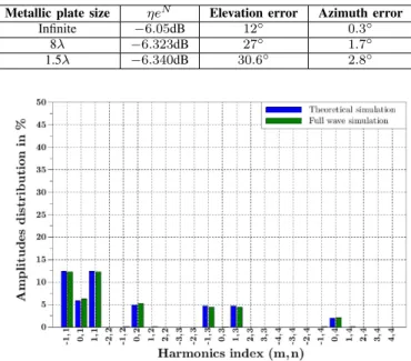
TABLE I: Criterion of the estimation efficiency computed from full wave simulations according to maximal DoA error.
Metallic plate size 𝜂𝑒𝑁 Elevation error Azimuth error
Infinite −6.05dB 12∘ 0.3∘
8𝜆 −6.323dB 27∘ 1.7∘
1.5𝜆 −6.340dB 30.6∘ 2.8∘
Fig. 12: Amplitudes distribution of the outgoing spherical harmonics coefficients associated with the electric field -Infinite plate: Theoretical (blue) and FEKO (green).
Fig. 13: Amplitudes distribution of the outgoing spherical harmonics coefficients associated with the magnetic field -Infinite plate: Theoretical (blue) and FEKO (green).
Secondly, a vector sensor of 3 co-located realistic dipoles with different sizes of metallic plate has been simulated. These full wave simulations have allowed to validate that the computation of the estimation efficiency takes into account the radiation perturbations. However the 3D DoA estimation accuracy of a realistic vector sensor with this spherical mode approach is sensitive to the antenna elements radiation and to the surrounding perturbations. But for 2D direction finding, the sensor retains good performances. In future work, the prototype of the sensor {Ez, Hx, Hy} will be developed to validate the computation of the criterion efficiency in a real environment. According to the measured DoA accuracy, an
Fig. 14: Amplitudes distribution of the outgoing spherical har-monics coefficients associated with the electric field: Infinite plate with theoretical simulation (blue) and Finite plate of 1.5𝜆 with FEKO (green).
Fig. 15: Amplitudes distribution of the outgoing spherical harmonics coefficients associated with the magnetic field: Infinite plate with theoretical simulation (blue) and Finite plate of 1.5𝜆 with FEKO (green).
optimization of the vector sensor design could be performed to improve its performances.
REFERENCES
[1] G. Hatke, “Conditions for unambiguous source location using polarization diverse arrays,” in Asilomar conference on signals, systems and comput-ers, 1993.
[2] A. Nehorai and E. Paldi, “Vector-sensor array processing for electro-magnetic source localization,” IEEE Transactions on Signal Processing, vol. 42, pp. 376–398, 1994.
[3] A. Chabory, C. Morlaas, and B. Souny, “Efficiency characterisation of vector-sensor antennas with distributed elements for 3d direction finding,” in IEEE-APS Topical Conference on Antennas and Propagation in wireless Communications, 2011, pp. 819 – 822.
[4] A. Chabory, C. Morlaas, R. Douvenot, and B. Souny, “Reduction of the sensor number in distributed vector-antennas for 3d direction finding,” in 15th International Symposium on Antenna Technology and Applied Electromagnetics, 2012.
[5] R. Harrington, Time-Harmonic Electromagnetic Fields, D. G. Dudley, Ed. Wiley-IEEE Press, 2001.