HAL Id: hal-01022154
https://hal-enac.archives-ouvertes.fr/hal-01022154
Submitted on 30 Sep 2014
HAL is a multi-disciplinary open access
archive for the deposit and dissemination of
sci-entific research documents, whether they are
pub-lished or not. The documents may come from
teaching and research institutions in France or
L’archive ouverte pluridisciplinaire HAL, est
destinée au dépôt et à la diffusion de documents
scientifiques de niveau recherche, publiés ou non,
émanant des établissements d’enseignement et de
recherche français ou étrangers, des laboratoires
Comparison between the future GPS L1C and
GALILEO E1 OS signals data message performance
Axel Javier Garcia Peña, Christophe Macabiau, Anne-Christine Escher,
Marie-Laure Boucheret, Lionel Ries
To cite this version:
Axel Javier Garcia Peña, Christophe Macabiau, Anne-Christine Escher, Marie-Laure Boucheret,
Li-onel Ries. Comparison between the future GPS L1C and GALILEO E1 OS signals data message
performance. ION ITM 2009, International Technical Meeting of The Institute of Navigation, Jan
2009, Anaheim, United States. pp 324 - 334. �hal-01022154�
Comparison between the future GPS L1C and
GALILEO E1 OS signals data message
performance
Axel Garcia Pena, Centre Nationale d’Etudes Spatiales (CNES)/TeSA Christophe Macabiau, Ecole Nationale de l’Aviation Civile Anne-Christine Escher, Ecole Nationale de l’Aviation Civile Marie-Laure Boucheret, IRIT, Université de Toulouse/ENSEEIHT
Lionel Ries, Centre National d’Etudes Spatiales
BIOGRAPHY
Axel Garcia Peña is a telecommunication engineer. He followed a European program of double degree: he graduated in 2006 from SUPAERO (Ecole Nationale Superieure de l'Aeronautique et de l'Espace) in Toulouse, France and he also obtained the engineer degree from ETSETB-UPC (Escola Tecnica Superior d’Enginyeria de Telecomunicacions de Barcelona – Universitat Politecnica de Catalunya, Spain) in 2006. He is now a PhD Student at ENAC and studies improved methods/algorithms to better demodulate the GPS signals as well as future navigation message structures.
Christophe Macabiau graduated as an electronics engineer in 1992 from ENAC in Toulouse, France. Since 1994, he has been working on the application of satellite navigation techniques to civil aviation. He received his PhD in 1997 and has been in charge of the signal processing lab of the ENAC since 2000.
Anne-Christine Escher graduated as an electronics engineer in 1999 from the ENAC in Toulouse, France. Since 2002, she has been working as an associate researcher in the signal processing lab of the ENAC. She received her Ph.D. in 2003.
Marie-Laure Boucheret graduated from the ENST Bretagne in 1985 (Engineering degree in Electrical Engineering) and from Telecom Paris in 1997 (PhD degree). She worked as an engineer in Alcatel Space from 1986 to 1991 then moved to ENST as an Associated Professor then a Professor. Currently, she is a Professor at ENSEEIHT. Her fields of interest are digital communications (modulation/coding, digital receivers, multicarrier communications…), satellite onboard processing (filter banks, DBFN…) and navigation system.
Lionel Ries is a navigation engineer in the "Transmission Techniques and Signal Processing Department", at CNES since 2000. He coordinates GNSS technical activities, including GNSS signals performances evaluation and receiver algorithms development (BOC and MBOC, GIOVE, GPS L2C & L5, etc.). He graduated from the Ecole Polytechnique de Bruxelles, at Brussels Free University (Belgium) and then specialized in space telecommunications systems at Supaero (ENSAE), in Toulouse (France).
ABSTRACT
GPS L1C and GALILEO E1 OS are two of the current navigation open service signals being developed nowadays. GPS L1C is the US open signal and is being conceived in order to provide enhanced capabilities to civilian users in relation to previous GPS signals and in order to achieve interoperability with Galileo’s Open Service signal [1, 8]. GALILEO is the European system and is being developed in order to obtain independence from any other navigation system, while searching to reach maximum interoperability with other GNSS systems, for instance with GPS. Nevertheless, GALILEO, being a navigation system of a new generation, also searches to provide a very high positioning performance by means of its open service signal E1 OS.
One of the aspects being improved by both systems is the data message demodulation/decoding process, which has proven not to provide a sufficient level of performance in low C/N0 environments such as indoor and narrow urban ones. However, each signal has been conceived in a very different form and some of the design differences such as the signal channel relative power distribution between the data and pilot channel, the symbol rate, channel code, etc, affect directly the performance of the demodulating/ decoding process. Therefore, since they are different and
thus their behaviour is not the same with respect to channel impairments, an arising question is to know the pros and cons of each design.
The aim of this paper is to make a first simplified performance comparison of the GPS L1C and GALILEO E1 OS data message decoding process by observing the BER, the WER (Word Error Rate) and the EER (Ephemeris Error Rate) as functions of the C/N0. More specifically, this paper seeks these figures of merit in the subframes (GPS L1C) and words (GALILEO E1 OS) containing the ephemeris and clock corrections.
I. INTRODUCTION
The study presented in this paper is part of a Ph. D. thesis whose main objective is the optimization of the demodulation/decoding performance of the GNSS navigation message ephemeris data. One of the basic steps of this Ph. D. thesis is the analysis the current performance of two of these new GNSS signals, GPS L1C and GALILEO E1 OS. This analysis was done from the current public available documents of the signals: Draft GALILEO E1 OS ICD and IS-GPS-800.
Two of the new GNSS systems being developed nowadays are the GPS III, the evolution of the current GPS and the modernized GPS, and the European system of navigation, GALILEO. These two systems incorporate a lot of improvements compared to the first GPS such as new data message structures, new pseudo-range codes, etc. Moreover, each system contains its own open service signal, L1C for GPS and E1 OS for GALILEO, a free signal accessible by any user. These signals are of great interest since they will be the most exploited ones due to their free accessibility. Therefore, the different performance obtained by each one such as the time of acquisition, the demodulation threshold, etc, are interesting points to be assessed.
Nevertheless, a significant difference between the open signals GALILEO E1 OS and GPS L1C is the service called SoL (Safety of Life) only provided by the former one. This means that the GALILEO E1 data message, called by this paper GALILEO E1 OS, apart from carrying the ephemeris and clock information, also transports additional information required by the SoL service. Thus, whereas the OS users only extract part of the information (ephemeris and clock) contained in the whole E1 navigation message, the SoL users have to decode it all.
One of the performance previously commented is the demodulation threshold. This performance connects the C/N0 (Signal Power to Noise Power Spectral Density Ratio) available at a receiver’s antenna with the BER (Bit Error Rate) and the WER (Word Error Rate) of the navigation message. In other words, the minimum useful signal power in relation to the noise power density at the
receiver antenna output that is required in order to obtain a determined value of BER or WER; these last values being fixed by the type of application implemented. For example the civil aviation requires a WER of 10-3 [RTCA,2008] and a WER of 10-4 [EUROCAE, 2007]. However, the most interesting demodulation performance is associated to the demodulation/decoding of the subframes (GPS L1C) or the words (GALILEO E1 OS) containing the ephemeris and clock corrections of the transmitting satellite. The reason is the following: they are the minimum information required to obtain a receiver final position. Therefore, many users are mainly interested in the percentage of times that a single ephemeris/clock set is recovered (error free) in relation to the number of times that this set has been received. Consequently, a new and most important figure of merit is defined in this paper, the Ephemeris Error Rate (EER). Nevertheless, the BER and the WER are still relevant because they indicate the contribution of some design aspects such as the channel code and the quality of the ephemeris information organization inside a frame to the demodulation performance.
Note that we have to differentiate between the decoding and the demodulation. The decoding is the process of translating received messages into codewords of a given code. This translation is accomplished by estimating the plus probable emitted codeword for each received message. The demodulation process is the act of extracting the original information-bearing signal from a modulated carrier wave. Therefore, the demodulation process is accomplished after applying the decoding, once the codewords are transformed into information words. The decoding is a part of the demodulation.
This demodulation performance achieved for GPS L1C and GALILEO E1 OS is not the same since they are designed differently. Therefore, the remaining question is: which of these two data messages accepts a lower C/N0 value that, after the demodulation/decoding process, do not surpass the maximum BER of the system?
The answer to these questions depends on the following relevant factors conditioning the demodulation performance: the data message structure (mainly the channel codes), the data message content, the symbol transmission rate and the signal channel relative power distribution between the data and the pilot channels. Each one has a direct influence over the relationship between the C/N0 and the BER: the channel code establishes a direct association between the BER and the Eb/N0 (Energy per Bit to Noise Power Density Ratio), the power distribution establishes the value of the data signal power (Cdata) in relation to the signal power at the receiver’s antenna (Ctotal or C) and the symbol transmission rate connects the bit’s energy (Eb) with Cdata. Finally, the data message content can increase the Eb level by accumulating different received sets of the same
ephemeris data. Nevertheless, a better and more detailed explanation of the influence of these factors is presented in a subsection of this paper.
This possibility of accumulating received sets of ephemeris data or part of them containing the same information, the same keplerian parameters and clock corrections, establishes a new strategy of signal/data processing for the GNSS receivers and thus a new type of demodulation performance. That is why two types of performance are studied in this paper: the first one is the level of C/N0 required by each signal to obtain a determined value of BER, WER and EER when only one frame is processed i.e. the performance of the code, the data structure, the symbol transmission rate and the power distribution. The second one searches, for each navigation signal received with a determined level of C/N0, the average time required (average number of frames to be accumulated) by a user in order to obtain a determined value of BER, WER and EER. This second performance indicates the signal time-of-wait and capability of providing the GNSS users with the information necessary to calculate their position, because a receiver will always try to accumulate the received data in order to increase the C/N0 level.
Until now, this paper has been talking about the demodulation performance, but what exactly is this performance in physical terms? This performance is the difference of power attenuation supported by each signal when the GNSS receiver works at the worst possible environment of an application (maximal allowed BER). In other words, for a maximum BER allowed by a given application, a different minimum Cm/N0 is found for each GNSS signal (the index m specifies the application). However, each system transmits a signal which is received at receiver antenna output with a power equal to Ctotal. Therefore, each signal can have a different power attenuation equal to: Am,signal = Ctotal, signal – Cm signal and still being able to obtain the BER demanded by the application. This means that this difference of power attenuation between the signals determines which system can work at the maximum determined BER in worse environments than the other one, environments with bigger power attenuations.
The scenario chosen by this paper to compare the GPS L1C and GALILEO E1 OS signals is simplified by the assumptions that the synchro-frame and tracking process are already achieved. Nevertheless, they affect the numerical results of C/N0 obtained in this study because these assumptions, for example, modify the relationship between the Eb/N0 and C/N0 values and always allow the coherent addition of received frames containing the same ephemeris data. Therefore, this paper presents a simplified comparison of the data message decoding process of GPS L1C and GALILEO E1 OS signals, which
can be used as a first evaluation of both signal performances.
Finally, this study does not analyze any other aspect of the new signals GPS L1C and GALILEO E1 OS or any aspect of the high level trade-off of the design of each system.
This paper presents first the main signal differences conditioning the demodulation performance and how exactly they influence it. Afterwards, the assumptions of the study are introduced and they are followed by a theoretical analysis of the demodulation performance of the two signals. Finally, the simulations results and the conclusions are discussed.
II. MAIN SIGNAL DIFFERENCES
The main differences of design between the GPS L1C and GALILEO E1 OS signals which condition the demodulation performance are the signal channel relative power distribution, the symbol transmission rate, the data message structure and the data message content.
A. Signal Channel Relative Power Distribution:
Both signals, GPS L1C and GALILEO E1 OS are received with the same level of power at the receiver antenna output. However, they distribute this power differently between the different channels forming them. Therefore, since the data channel and the pilot (dataless) channel are uncorrelated, the total received power can be expressed as:
Total signal power = Data signal power + Pilot signal power
The power distribution over each channel is the following:
Signal Data Channel Pilot Channel
GPS L1C 25% 75%
GALILEO E1 OS 50% 50%
Table 1: Signal Channel Relative Power Distribution between the data and pilot channels of the GPS L1C and GALILEO E1 OS
signals
B. Symbol Transmission Rate (RD):
The symbol transmission rate is 2.5 times higher for the European signal:
Signal GPS L1C GALILEO E1 OS
Symbol Tx Rate (RD) 100 symb/s 250 symb/s Table 2: Symbol Transmission Rate for GPS L1C and GALILEO
C. Data Message Structure:
The data message structure is completely different for GPS L1C and GALILEO E1 OS. In fact, both the size and frequency of the information units (word, subframe, frame…) and the implemented channel code are different for each navigation signal.
This paper is not going to present a detailed description of the data message structure of both signals since the complete specifications can be found in the documents [1][2]. Nevertheless, for a better understanding of the analysis, some general characteristics of the messages are given:
• GPS L1C:
o Frame period = 18s
o Subframe 2 (ephemeris data) Size = 600 information bits
o Channel Code over subframe 2: LDPC Channel Code Rate: r = 1/2
Systematic: The information bits are not modified
o Block Interleaver size (symbols): Applied on subframes 2 and 3 38 rows and 46 columns
Figure 1: GPS L1C frame structure • GALILEO E1 OS:
o Frame period = 30s
o Words 1 to 4 Contain the ephemeris and clock corrections
o Word duration = 2s; Word size = 240 information bits; Each word is constituted by 2 pages
o Page Period = 1s; Page Size = 120 information bits
o Channel Code over a page: Convolutional Code
Chanel Code Rate: r = 1/2 G1 = 171o; G2 = 133o Non systematic
Each page contains 6 tail bits meaning that the convolution code is used as a block
code: the size is fixed and the initial and final states are known.
o Block Interleaver size (symbols): Applied on a page 30 rows and 8 columns
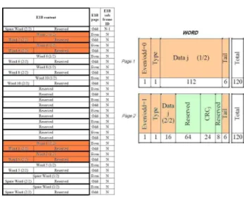
Figure 2: GALILEO E1 OS frame structure.
D. Data Message Content:
The demodulation performance analysed by this study is the ephemeris data demodulation performance of the signals GPS L1C and GALILEO E1 OS. Therefore, the main content of the analysed units is the ephemeris/clock corrections data and it is found on the subframe 2 for GPS L1C and on the words 1 to 4 for GALILEO E1 OS. This content (ephemeris/clock) is constant during at least 15 minutes for GPS L1C but varies at any moment for GALILEO E1 OS. More specifically, GALILEO E1 OS has a constant part (colored orange on figure 2) and a reserved part (colored green on figure 2). Therefore, as it is usual, this reserved part is considered variable; or in other words, the reserved part bits of the frame n may not be equal to the ones of the frame n-1 and n+1.
To sum up, whereas on the GPS L1C signal all the bits of a subframe 2 can be added coherently to others bits of other subframes 2 (inside an interval of at least 15m), only the first page of a word and a part of the second one can be added on the GALILEO E1 OS signal from one page to the next one.
III. INFLUENCE OF THE MAIN SIGNAL DIFFERENCES
In this subsection, the reason why these main signal differences affect the final value of C/N0 is explained.
A. Signal Channel Relative Power Distribution:
The signal channel relative power distribution affects directly the data message power because not all the signal power fed to the satellite antenna is used to carry the data message. In fact, the designers can choose which percentage of power is assigned to each component of the signal: the data and the pilot channels. Therefore, depending on this distribution, the values sampled by the receiver are more or less affected by the noise, because the more power the data component has, the higher the amplitude of the symbols in relation to the noise is; in other words, the C/N0 increases. Therefore, the more power is assigned to the data channel, the better for demodulation purposes. Nevertheless, this statement is only completely true when the tracking process is assumed to be perfect, because the tracking performance, which depends on the pilot power, also affects the amplitude of the data symbols.
Thus, the mathematical expression associated to the signal channel relative power distribution is:
total total data N C on Distributi N C function N C 0 0 0 1 ⋅ = =
B. Symbol Transmission Rate (RD):
The influence of the symbol transmission rate is to relate the C/N0 value with the Eb/N0 because the Eb/N0 parameter directly determines the level BER of the decoded message. Thus, admitting that the data channel signal power Cdata at the receiver antenna output is determined by the total signal power Ctotal at the receiver antenna output and the signal channel relative power distribution (D), the Eb available at the receiver depends on this received power Cdata, on the channel code rate (r) and on the transmission rate (RD) according to the following relationship: BER N Eb r T N C R r N C D data D data ⇔ = ⋅ = ⋅ ⋅ 0 0 0 1
where TD: the period of a symbol
This mathematical expression is valid because the symbol period conditions the design of the receiver filter which maximizes the SNR being the SNR proportional to Eb/N0. In fact, this period sets the bandwidth of the filter (BD=1/TD). Therefore, the bigger the rate is, the less noise is filtered, and thus the bigger the noise power is; which leads to a diminution of the SNR value.
Another physical explanation of the symbol transmission rate influence is that a sampled value dn is obtained after
accumulating the signal value for an entire symbol period.
This operation is equivalent to an integral, meaning an averaging of the input noise. Therefore, the longer is the symbol period, the better average of the noise is obtained, which for a white noise is 0. Moreover, the symbol period controls the energy of the symbol Es (Eb = Es/r). In fact, the symbol energy (Es) is equal to the useful signal power (C) multiplied by the symbol period (TD) and thus the longer the symbol period is, the bigger its energy is and, as said before, the less influence the noise has. And this decreasing of the noise influence is translated into a smaller quantity of final errors or into a lower BER. To sum up, for the same C/N0, the transmission rate (RD) defines the symbol energy (Es) that, at the same time, determines the BER. In other words, the transmission rate (RD) determines the value of C/N0 required to obtain a desired BER for a given channel code.
C. Data Message Structure:
The data message structure determines the relationship between the Eb/N0 and the BER.
Eb/N0 ↔ BER
More specifically, this relationship is defined by the channel code and the unit of information (word, subframe) where this channel is applied. In this study, the information is the ephemeris and the clock corrections. Therefore, the channel code and the information unit are different for each signal.
In fact, the relationship between the Eb/N0 and the BER is specifically defined by the capacity of correction of each channel code and even for the same type of codes, the size of the information unit where the code is applied changes this correction capacity; the longer the information unit is, the better performance the channel code has.
D. Data Message Content:
The influence of the data message content depends on the nature of the carried information and, more concretely, on its change; in other words, it depends on the repetition of the information from one frame to the next ones. This is detailed below:
If some information is repeated on the frame n and on the frame n+1, part of the coded word (bits) containing/representing this information can be equal on both frames; this quantity depending on the implemented channel code. Therefore, the receiver can simply add one sampled value to the other since they are equals. This addition is translated into an increase of the Eb/N0 value because the useful signal is coherently added (same sign) whereas the noise, being an independent random variable, has a sum contribution either positive or negative.
Therefore, if after the addition the new sample is divided by the number of added components, the useful signal power remains constant whereas the noise being averaged is transformed into a new noise with a smaller power spectral density level. Another way of interpreting this coherent addition is to calculate the new power without dividing the new sample. On this case, it is easy to see that the new useful signal power (power 2 of the symbol amplitudes’ addition) increases more than the new noise power (addition of the powers 2 noise amplitudes). Additionally, note that the case where all the information is repeated from one frame to the next ones (changing at some point on the future), the coded frames are always equal regardless of the implemented channel code.
IV. ASSUMPTIONS OF THE STUDY:
In this paper, the assumptions made in order to simplify the calculations providing the searched performance are presented and justified. There are 3 main assumptions: the presence of an AWGN (Additive White Gaussian Noise), the assumption of an ideal coherent tracking and the absence of the synchro-frame process. Each of these is discussed below.
A. Additive White Gaussian Noise
The most common noise found in nature is the thermal one which can be modelled as an additive white Gaussian noise. For this study, no specific channel model is considered; we only assume an AWGN channel model. The power of the AWGN and, consequently, its amplitude is calculated from the useful signal data power (Cdata), from the transmission symbol rate (RD) and from the desired C/N0. Besides, the useful signal data power (Cdata) is calculated from the total signal power (Ctotal).
B. Seamless tracking process hypothesis
In order to simplify the study, the contribution of the delay and the phase tracking process on the sampled value is removed. In fact, the hypothesis taken by this document is that both the PLL and the DLL have already been applied and have lead to a perfect estimation of the phase and delay values. The model where we start from is the classical model for the correlator output:
)
ˆ
cos(
)
ˆ
(
)
)
1
((
)
)
1
(
ˆ
(
τ
+
k
+
T
=
Ad
k
+
T
⋅
R
τ
−
τ
⋅
θ
−
θ
r
i D D Where:• ri(n): Sampled signal at the correlator output at
time n
• A: Amplitude of the data symbol • TD: Duration of the data symbol
• d(n): Bit n of the data message • τ: Delay introduced by the channel • θ: Phase introduced by the channel
• R(x): Correlation function of the GPS L1C or GALILEO E1b PRN code.
Therefore, if the estimations of the phase and the delay are accurate enough not to affect the final sampled value, the former expression becomes:
1
)
)
1
((
)
)
1
(
ˆ
(
ˆ
ˆ
+⋅
=
+
=
+
+
⇒
≈
≈
k D D ik
T
Ad
k
T
A
d
r
τ
τ
τ
θ
θ
To sum up, if the tracking is accurate enough, the demodulation process is not affected by it. However, a degraded tracking increases the BER of the decoded data message and also the pseudorange measurement. In this paper, we assume perfect ideal tracking.
C. Seamless synchro-frame process hypothesis
We also assume that the synchro-frame has already been done. The synchro-frame process consists of searching the beginning of a page/word/subframe in the continuous stream of received bits. Therefore, once this first identification has been done, all the information can be recovered since all the fields, words, frames, etc, are easily located inside the stream of bits (from the demodulation of certain fields).
The main consequence of this assumption is that all the pages or subframes are recovered and none of them is lost. Therefore, the simulation will not bother on synchronizing the frame but it will always know where to find the beginning of the frame.
Note that this assumption corresponds to the case where the user has already tracked the signal and has already achieved the synchro-frame, then enters into a building or a zone with loss of the direct paths (or with an increasing of multipath effects) but he is still capable of tracking and thus there is no need of searching the synchronization again. In other words, the only main change is a decreasing of the C/N0 value since the available signal power is smaller than before entering this new environment.
V. THEORETICAL STUDY
A first theoretical study of the relevant factors conditioning the demodulation performance can be done from the available data.
First, the signal channel relative power distribution and the symbol transmission rate provide a relationship
between the C/N0 at the receiver antenna output and the Eb/N0. The formula relating the terms is:
(
R
r
D
)
N
E
N
C
D dB b dB total⋅
⋅
+
=
10
log
0 0 Where:- RD is the symbol transmission rate
- D is the power distribution assigned to the data channel
- r is channel code rate
This expression connects the Eb/N0 required for the channel code of the navigation message in order to obtain a determined BER with the C/N0 required at the receiver antenna output in order to obtain this same BER. The conversion from one parameter to the other is done through the addition of a term which depends on the two previous factors, power distribution and transmission symbol rate, plus the channel code rate. However, the channel code rate is the same for both signals; therefore r does not condition the comparison of performances. Applying the numerical data presented on the section II for each signal:
GPS L1C: - TD = 100 bps; r = 1/2; D = 1/0.25 = 4;
dB
N
E
N
C
LDPC dB b dB23
0 0+
≈
GALILEO E1 OS: - TD = 250 bps; r = 1/2; D = 1/0.5 = 2;dB
N
E
N
C
Viterbi dB b dB24
0 0+
≈
From this first numerical result some preliminary conclusions can be extracted. First, assuming the same channel code is implemented for each GNSS signal, the Eb/N0 required for a determined BER (fixed by an application) is equal for both signals. However, the C/N0 needed is 1dB higher for GALILEO E1 OS, or in other words, the signal GPS L1C supports an additional attenuation of 1dB. Therefore, GALILEO users will not be capable of demodulating the ephemeris and clock corrections in environments where GPS users will. Second, if the implemented channel codes are different and the GPS L1C one has a better error correction capacity, this additional attenuation grows. In fact, this situation is exactly the real one since the LDPC implemented in GPS L1C has much better performance than the convolutional code of GALILEO. Taking as reference [3] and [4] results, for a BER value equal to
10-3, the difference in the required Eb/N0 between the codes is 1.5dB and for a BER of 10-5 it is 2.2dB. Therefore, the difference in terms of C/N0 at the receiver antenna output is approximately 2.5dB for BER equal to 10-3 and 3.2dB for a BER equal to 10-5. This means that GPS users can demodulate the GPS L1C signal with a BER equal to 10-5 in environments where the received signal power is half of the signal power in the worst environments where the GALILEO E1 OS signal can be demodulated at this BER.
Third and final, this conclusion can also be drawn for the WER and the EER, assuming that all the binary errors are independent. Therefore, better WER and EER are obtained with GPS L1C.
Until now, the performance searched with this theoretical study only takes into account the reception of one set of ephemeris/clock corrections. However, during the introduction we mentioned the possibility of accumulating several sets containing the same information, which will be the common strategy of any GNSS receiver. Therefore, the theoretical study continues with the inspection of this second demodulation performance.
For GPS L1C, the content, ephemeris and clock corrections, of the subframe 2 is the same for at least 15 minutes: the updating time of the ephemeris and clock corrections set is known. This means that several subframes can be accumulated. This accumulation implies an increment in the Eb/N0 ratio, because the Eb parameter grows more than the N0 value. For example, the gain of the accumulation of 2 subframes is calculated next:
+
⋅
=
+
⋅
=
)
(
)
(
)
(
)
(
2 2 1 1t
n
d
A
t
S
t
n
d
A
t
S
n n n n where:- S1n(t) is the sample n of the 1st received subframe - S2n(t) is the sample n of the 2nd received subframe - A is the amplitude of the useful signal
- dn is the coded bit n
- n1(t), n2(t) are independent AWGN Therefore:
(
)
= ⋅ = ⋅ ⋅ = ⋅ + = = ⋅ = ⋅ = + 0 2 0 1 0 2 0 2 0 1 0 2 0 2 2 2 · 2 2 1 1 N E N E N T A R N A A P P N E N T A R N A P P words b word b D D N S S word b D D N SWhich implies a growth of 3dB from the original Eb1-word value where only 1 word has been processed to the new accumulated one Eb2 words value where two words have been accumulated. Repeating the process for more accumulations, the gain obtained is:
(
numberofaccumulatedsubframes)
Gain=10 ⋅log10
For GALILEO E1 OS, there is only one fraction of the word that remains constant from one frame to the next one. In fact, one part is constant (ephemeris and clock corrections information) and the other is reserved and thus is considered variable. However, since the implemented channel code is a convolutional code, all the constant parts can be added: the state previous to the encoding of the constant bits only depends on the past bits. Therefore, more than 50% of the word is known. In fact, on one hand, the entire page 1 is constant and thus the new Ebn words obtained after the word accumulation achieves the same gain as the LDPC bits. On the other hand, the page 2 can be divided into 2 parts: the constant part which has a low probability of containing any errors, the estimation of the received symbol values is more robust, and the variable part which does not improve with the accumulation process. Therefore, a first conclusion is that the accumulation of the GALILEO E1 OS correlation samples will not help to reduce the WER as much as for the GPS L1C, but still provides a gain; this gain could be calculated as the average between the variable and constant bits gain. Nevertheless, there is an important impediment to introduce.
First, the GNSS systems have the policy of discarding all the wrong decoded words/subframes. The signal GALILEO E1 OS is not an exception and in order to accept a word as valid, the word has to pass the verification of the CRC-24Q included in its content. The problem is that some variable parts of this word are also protected by this CRC, which makes the CRC be variable. Therefore, even if part of the word decreases the Eb/N0 values required to obtain a level of BER, the remaining part will still be as vulnerable as before and the CRC will still fail. To sum up, the accumulation of words of the GALILEO E1 OS message makes the bits of the constant parts of a word more robust to the noise, which means that the possible errors introduced by the channel on them are more easily corrected than the errors introduced on the bits of the variable parts. Before the accumulation, the entire word is weak against the demodulating errors, afterwards, only the variable parts are.
Second and last, whereas on GPS L1C the updating time of the new ephemeris/clock corrections sets is known, the updating time of GALIEO E1 OS has no constraints, meaning that the updates are completely random. Therefore, it is impossible to ensure that two consecutives words , from frame n to frame n+1,contain the same ephemeris and thus the accumulation cannot be guaranteed.
Finally, before summarizing the performance of the accumulation process, another important difference between both signals is the duration of a frame. GPS L1C
has a frame duration of 18 seconds whereas GALIELO E1 OS has a frame duration of 30 seconds. Therefore, the accumulating process will be achieved faster with the GPS signal.
To sum up, the accumulation strategy of subframes or words on the signal GPS L1C obtains better results and is faster accomplished than on the signal GALILEO E1 OS which, due to the randomness of its ephemeris and clock corrections updates, cannot be guaranteed.
VI. SIMULATION BLOCK SCHEME
The simulation implemented in order to calculate the BER, WER and EER associated to the channel code of each navigation signal is the following:
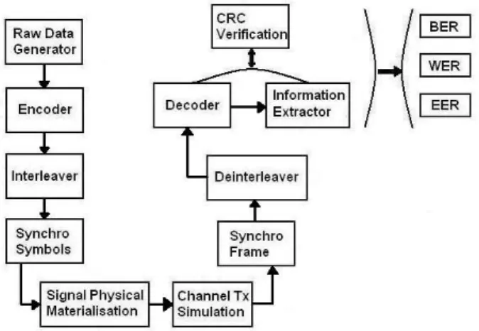
Figure 3: Simulation Block Scheme It is briefly detailed below:
Raw Data Generator: Creates the message content (dummy information) and generates the CRC-24Q associated to this data. It reproduces the constant parts from the frame n to the frame n+1 if necessary.
Encoder: Applies the LDPC code for GPS L1C and the convolutional code (171,133) for GALILEO E1 OS.
Interleaver: Interleaves the page or the subframes.
Synchro-symbols: Only implemented for GALILEO E1 OS. Inserts the synchro-symbols for each page.
Signal Physical Materialization: Converts the binary message (0/1) into a physical one (+1/-1) ready to be transmitted into the channel.
Channel Tx Simulation: Generates the errors introduced by the AWGN during the transmission of the message into the channel.
Synchro-Frame: Detection of the beginning.of the frame. This process is always perfectly achieved.
Deinterleaver: Deinterleaves the page/subframes.
Decoder: Application of the FEC. The implemented decoding algorithms are [5] for GPS L1C and the Viterbi algorithm [6] [7] for GALILEO E1 OS.
CRC verification: Executes the CRC verification as specified in [1] and [2].
Information Extractor: Extracts the information if the CRC verification succeeds.
BER, WER and EER: Calculates the BER, the WER and the EER of the transmission.
VII. SIMULATION RESULTS
The simulations illustrated in this paper have the objective to evaluate the performance of the implemented channel code of each GNSS navigation signal. Three different simulations have been run, the first one compares the BER between GPS L1C and GALILEO E1 OS signals, the second one compares the WER and the third one the EER.
The following figure illustrates the results of the BER comparison:
Figure 4: Comparison of the ephemeris decoding performance only depending on the implemented channel code between GPS L1C and
GALILEO E1 OS: BER vs Eb/N0 (dB)
In the previous figure it can be observed that the difference of performance is a bit smaller than the expected one from the theoretical study. For a BER equal to 10-3 the gain difference is 1dB (1.5 theoretical study) and for a BER equal to 10-5 it is 2.1dB (2.2dB theoretical study).
In this comparison, the cases where more than 1 word is used to decode the information have not been inspected since the accumulation at a bit level is not possible for GALILEO E1 OS; not all the bits can be accumulated. Figure 5 illustrates the results of the WER comparison. The gain difference between the signal GPS L1C and GALILEO E1 OS when only 1 word has been received is equal to 1.5dB for a WER equal to 10-2 and 2.1dB for a WER equal to 10-3.
Moreover, figure 5 shows that the case where 1 word is used to decode GPS L1C navigation message has better performance than the case where 2 words are used to decode GALILEO E1 OS. Besides, the case where 2
words are used for GPS L1C is not presented because even for the case where Eb/N0 is equal to 1dB, none wrong word has been found among the 400000 tested words. Therefore, it can be concluded, as was expected, that the accumulation strategy works better for GPS L1C than for GALILEO E1 OS.
Figure 5: Comparison of the ephemeris decoding performance only depending on the implemented channel code between GPS L1C and
GALILEO E1 OS: WER vs Eb/N0 (dB)
Last, the figure illustrating the results of the EER comparison is the following:
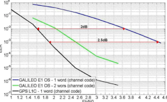
Figure 6: Comparison of the ephemeris decoding performance only depending on the implemented channel code between GPS L1C and
GALILEO E1 OS: EER vs Eb/N0 (dB)
The gain difference between the signal GPS L1C and GALILEO E1 OS when only 1 word has been received is equal to 2dB for an EER equal to 10-2 and 2.5dB for an EER equal to 10-3.
Moreover, the same remarks about the accumulation strategy as these of the WER comparison can be presented. And, it can be observed that, as was expected from the theoretical study, the longer the information word, the better the performance. Besides, it can also be noticed that the division into different words of an ephemeris for GALILEO E1 OS worsens the EER in relation to its WER.
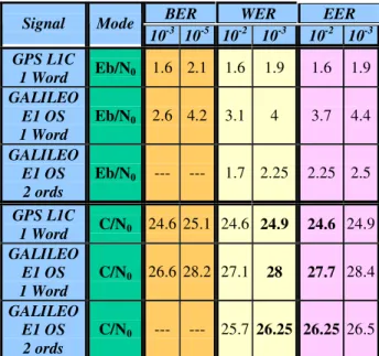
Finally, the following table summarizes the gain difference in terms of Eb/N0 (dB) and C/N0 (dB) between
the two GNSS navigation signals for the demodulation performance:
BER WER EER
Signal Mode 10-3 10-5 10-2 10-3 10-2 10-3 GPS L1C 1 Word Eb/N0 1.6 2.1 1.6 1.9 1.6 1.9 GALILEO E1 OS 1 Word Eb/N0 2.6 4.2 3.1 4 3.7 4.4 GALILEO E1 OS 2 ords Eb/N0 --- --- 1.7 2.25 2.25 2.5 GPS L1C 1 Word C/N0 24.6 25.1 24.6 24.9 24.6 24.9 GALILEO E1 OS 1 Word C/N0 26.6 28.2 27.1 28 27.7 28.4 GALILEO E1 OS 2 ords C/N0 --- --- 25.7 26.25 26.25 26.5 Table 3: Summarizing table of the Eb/N0 and C/N0 (dB) values required to obtain a determined BER, WER and EER values of GPS
L1C and GALILEO E1 OS ephemeris demodulation performance. The transition from the Eb/N0 associated to each channel code to the C/N0 value is done by adding 23dB to GPS L1C signal and 24dB to GALILEO E1 OS signal as was calculated in the theoretical study part of this paper.
VIII. INFLUENCE OF THE TRACKING PROCESS:
The values summarized in the table 3 are conditioned by the assumptions set in this paper. The most important of these assumptions is the seamless tracking process because the estimation of the delay and the phase determines the relationship between the Eb/N0 and the C/N0 values. In fact, since the amplitude of the estimated value dndepends on these estimations, a bad estimation
means a decrease of the Eb/N0 in comparison with the value obtained with a perfect tracking for a given C/N0. Moreover, the impact of noise on these estimated delay and phase also depends on the C/N0 value; therefore the degradation of performance for low C/N0 is worse than the results presented in this paper.
Finally since GPS L1C signal distributes 75% of the power at the antenna receiver output to the pilot channel whereas GALILEO E1 OS signal distributes only 50%, a bigger difference favorable to GPS L1C on the demodulation performance in terms of C/N0 (dB) than the one calculated in this study should be expected between both signals.
IX. CONCLUSIONS
Several conclusions can be extracted from this paper. First, the ephemeris demodulation performance in terms of BER (2dB to 3.1dB for 10-3 to 10-5), WER (2.5dB to 3.1dB for 10-2 to 10-3) and EER (3.1dB to 3.5dB for 10-2 to 10-3) is better for GPS L1C than for GALILEO E1 OS. Second, the strategy where the words or the subframes are accumulated gives better results for GPS L1C than for GALILEO E1 OS. Moreover, even when using the word accumulation strategy of 2 words for GALILEO E1 OS, the signal GPS L1C with only 1 decoded word has a better ephemeris demodulation performance. Nevertheless, this accumulation cannot be guaranteed for GALILEO E1 OS due to the randomness of its ephemeris/clock corrections updates.
The main factors influencing these results are the different implemented channel codes and the frame organization of each GNSS signal. On one hand, the LDPC code; this channel code has a much bigger error correction capacity than any convolutional code decoded with the Viterbi algorithm. On the other hand, the division of the ephemeris into 4 short words instead of keeping them in a long subframe; two reasons explain the influence of this factor: first, the longer the information unit, the better the code performance. Second, the wrong decoding of one of the words carrying the ephemeris makes useless the good decoding of the others.
Finally, the future work of this study should recalculate all these results but considering the effect of the noise on the tracking process, the effect of a non ideal tracking on the demodulation and the thresholds values of tracking loss.
X. ACKNOWLEDGMETS
A.G.P. thanks to CNES and TéSA for the joint financing of the research fellowship.
XI. REFERENCES
[1] NAVSTAR GLOBAL POSITIONING SYSTEM, Navstar GPS space Segment/User segment L1C
interfaces, Draft IS-GPS-800, Aug 04, 2006
http://www.losangeles.af.mil/shared/media/document /AF-070803-064.pdf.
[2] Galileo OS SIS ICD, 23 May 2006 – DRAFT
[3] P. A. Dafesh, E. L. Vallés J. Hsu and D. J. Sklar, L. F. Zapanta, C. R. Cahn, Data Message Performance
for the future L1C GPS Signal, ION GNSS 20th International Technical Meeting of the Satellite Division, 25-28, September 2007, Fort Worth, TX
[4] John G. Proakis, Digital Communications, McGraw-Hill, 2000
[5] David J.C. MacKay, Radford M. Neal, Near Shannon
Limit Performance of Low Density Parity Check Codes, 12 July 1996, Electronic Letters
[6] A. J. Viterbi, “Error Bounds for Convolutional Codes and an Asymptotically Optimum Decoding Algorithm,” IEEE Transactions on Information
Theory, Vol. IT-13, pp. 260-269, 1967.
[7] A. J. Viterbi and J. K. Omura, Principles of Digital
Communication and Coding, McGraw-Hill, NY, 1979.
[8] J. W. Betz, M. A. Blanco, C. R. Cahn, P. A. Dafesh, et.al., Description of the L1C Signal, Proceedings of ION GNSS, Sept. 2006.