\
Conception and Experimental Investigation of Thermal Switches
byJohn Novak
Submitted to the Departments of Mechanical Engineering and Nuclear Engineering in Partial Fulfillment of the Requirements for the Degrees of
Master of Science in Mechanical Engineering and Master of Science in Nuclear Engineering at the
Massachusetts Institute of Technology
May 1995
© MIT 1995
Signature of Author
Department of Nuclear Engineering
May 12, 1995
Certified
by -
.
.
o,
es
Neil Todreas Department of Nuclear Engineering Thesis Advisor
Certified by .
-7
-- -
-
-M hael Driscoll
t/ -Department of Nuclear Engineering
., Thesis Advisor
Certified by - -..
Borivoje Mikic Department of Mechanical Engineering
, Thesis Advisor
Accepted by
Accepted by
... ' A.F. Henry
Department of Nuclear Engineering
~-~C¶i Chairman, Department Committee on Graduate Students
A. A. Sonin Department of Mechanical Engineering Chairman. Department Committee on Graduate Students
A$, SCH( JINSTITUTE
lJUN 7 1995
LIB.
Eng
-- r - -
Conception and Experimental Investigation of Thermal Switches by
John Novak
Submitted to the Departments of Mechanical Engineering and Nuclear Engineering in May 1995 in partial fulfillment of the requirements for the Degrees of Master of
Science in Mechanical Engineering and Master of Science in Nuclear Engineering
Thesis Abstract
A thermal switch is a device that can thermally couple and decouple a heat source and a heat sink. The research described in this thesis involved conceiving new thermal switch concepts, and experimentally investigating and developing some of them. Specifically, eighteen new thermal switch concepts were conceived, and the four most technologically feasible and economically affordable concepts were experimentally investigated and developed. The four thermal switch concepts chosen were:
1. Dissociation thermal switch 2. Particle Bed thermal switch 3. Wick thermal switch
4. Water (Evaporation-Condensation) thermal switch
These four thermal switch concepts were developed and tested via three different experimental setups. The first two experimental setups built were used to develop a dissociation and recombination algorithm for the chemicals that might be used for the dissociation and particle bed thermal switch. (Dissociation is the decomposition of a chemical into its constituents via thermal energy addition, and recombination is the recombining of these constituents to form the original chemical.) The third experimental setup built was used to investigate the heat transferring capability of the particle bed thermal switch, the wick thermal switch, and the water thermal switch for various on-mode (i.e., thermal-couple mode) setups and off-mode (i.e., thermal-decouple mode) setups. A successful dissociation and recombination algorithm was developed, and successful on-mode setups and off-mode setups were discovered for the wick thermal switch and the water thermal switch. The particle bed thermal switch was also able to thermally couple and decouple a heat source and a heat sink, but not as effectively as the wick thermal switch and the water thermal switch.
Thesis Supervisor: Dr. Neil Todreas
Acknowledgments
The author wishes to express his sincere gratitude to his sponsor and faculty
advisers. The sponsor, EPRI, provided solid, unwavering, financial funding while at the
same time allowing the author and the faculty advisers research freedom to meet the
objectives of the project. The two key faculty advisers, Professor Neil Todreas and
Professor Michael Driscoll, provided a wealth of ideas and information and very insightful
comments and criticisms. Lastly, the author wishes to thank Professor Borivoje Mikic for
all the heat transfer theory he imparted to the author through his courses which enabled the
successful design, performance, and completion of the research project.
Conception and Experimental Investigation of Thermal Switches Abstract .. . ...2 Acknowledgement ... ... ... 3 Table of Contents ... ...4 List of Tables ... . ...6 List of Figures ... 7 Chapter 1: Introduction ... . . . . .10
Chapter 2: Contemporary Passive Thermal Switches ... 17
2.1 Introduction ...17
2.2 High-Temperature Gas-Gap Thermal Switch ... 17
2.3 Electrolytic Thermal Switch ... 19
2.4 Material-Type Thermal Switches ... 21
2.5 Axial Heat Pipes ... 25
2.6 Radial Heat Pipe ... 44
2.7 Other Types of Heat Pipes ... 44
2.8 Thermal Syphon ... 46
2.9 Bistable Passive Thermal Switch ... 46
2.10 Temperature-Initiated Passive Cooling System ... 51
2.11 Chapter Summary ... ...56
Chapter 3: Conceived Passive Thermal Switches ... 62
3.1 Introduction ...62
3.2 Categorization and Description of Thermal Switches ... 62
3.3 Chapter Summary ... 82
Chapter 4: Dissociation and Recombination Experiments ... 83
4.1 Introduction ... 83
4.2 Preliminary Experiments ... 84
4.3 Recombination Experiments ... 9
4.4 Chapter Summary ... 104
Chapter 5: The Heat Transfer Coefficient Experiment...106
5.1 Introduction ... 106
5.2 Experimental Setup ... 106
5.3 Experimental Procedure and Raw Data Reduction Algorithm ... 130
5.4 Description of Thermal Switches and Reduced Results ... 137
5.4.1 Particle Bed Thermal Switch ... 137
5.4.2 Wick Thermal Switch ... 142
5.4.3 Water Thermal Switch ... 150
Chapter 6: Summary and Recommendations for Future Work ... 163
6.1 Introduction ... 163
6.2 Summary and Recommendations for Future Work ... 163
Appendix A
Appendix B
Appendix C
Appendix D
Appendix E
Raw and Reduced Data of Dissociation and Recombination Experiments ...Al
Components and Vendors Employed ... ...B 1
Mass Calculations for Dissociation Experiments ... C 1
Computer Program ... D
List of Tables
Table 2.1 Types of Thermal Switches ... 58
Table 3.1 Heat Conduction Types of Thermal Switches . ... 66
Table 3.2 Heat Convection Types of Thermal Switches ... 68
Table 3.3 Thermal Radiation Types of Thermal Switches ... 72
List of Figures Figure Figure Figure Figure Figure Figure Figure Figure Figure Figure Figure 1.1 2.1 2.2 2.3 2.4 2.5 2.6 2.7 2.8 2.9 2.10 Figure 2.11 Figure Figure Figure 2.12 2.13 2.14 Figure 2.15 Figure 2.16 Figure 2.17 Figure 2.18 Figure 2.19 Figure 2.20 Figure 2.21 Figure 2.22 Figure 2.23 Figure 2.24 Figure 2.25 Figure 2.26 Figure 2.27 Figure 2.28
Categorization of Existing and Conceived Thermal Switches ... 14
High Temperature Gas-Gap Thermal Switch ... 18
Electrolytic Thermal Switch ... 20
Shape-memory Thermal Switch ... ...22
Metal-impregnated Porous Ceramic Thermal Switch ...24
Axial Heat Pipe ... 26
Axial Heat Pipe with Inert Gas in On-Mode ... 28
Axial Heat Pipe with Inert Gas in Off-Mode ...28
Axial Heat Pipe with Inert Gas and Rigid-Wall Reservoir in On-Mode ... 29
Axial Heat Pipe with Inert Gas and Rigid-Wall Reservoir in Off-Mode ... 29
Axial Heat Pipe with Inert Gas and Bellowed-Wall Reservoir in On-Mode ... 31
Axial Heat Pipe with Inert Gas and Bellowed-Wall Reservoir in Off-Mode ... 31
Axial Heat Pipe with Bellowed Adiabatic Section in On-Mode ... 32
Axial Heat Pipe with Bellowed Adiabatic Section in Off-Mode ...32
Axial Heat Pipe with Inert Gas and Temperature Controlled Rigid-Wall Reservoir in On-Mode ... ... ...33
Axial Heat Pipe with Inert Gas and Temperature Controlled Rigid-Wall Reservoir in Off-Mode ... 33
Axial Heat Pipe with Inert Gas and Bellowed-Hollow-Wall Reservoir in On-Mode ... 35
Axial Heal Pipe with Inert Gas and Bellowed-Hollow-Wall Reservoir in Off-Mode ... 36
Axial Heat Pipe Utilizing Liquid Inventory Control ... 38
Axial Heat Pipe with Bendable Adiabatic Section ... 39
Axial Heat Pipe with Throttle Valve ... 40
Axial Heat Pipe with Expanding/Contracting Wick ... 42
Axial Heat Pipe with Magnetic Wick ... 43
Radial Heat Pipe ... 45
Thermal Syphon ... 47
Loop Thermal Syphon ...48
Thermal Syphon with Inert Gas ... 49
Bistable Passive Thermal Switch Without Air in the Cylindrical Shell ... 50
Figure 2.29 Temperature-Initiated Passive Cooling System ... 53
Figure 2.30 Categorization of Thermal Switches ... 57
Figure 3.1 Particle Bed Thermal Switch ... 75
Figure 3.2 Dissociation Thermal Switch ... 75
Figure 3.3 Change of Solid-Phase Structure Bar ... 75
Figure 3.4 Phase Change Thermal Switch ... 76
Figure 3.5 Variable Cross-Sectional Area Bar ... 76
Figure 3.6 Evaporation-Condensation Thermal Switch (with Fins) ...76
Figure 3.7 Liquid-Vapor Thermal Switch ... 77
Figure 3.8 Chamber Thermal Switch ... 77
Figure 3.9 Wick Thermal Switch ... 77
Figure 3.10 A Chemical Thermal Switch ... 78
Figure 3.10B Chemical Thermal Switch ... 78
Figure 3.11 Grain Growth on Hot Component Surface ... 79
Figure 3.12 Attachment of Grooved Wall to the Heat Source ... 79
Figure 3.13 Surface Spectral Characteristics (Temperature Increase) ... 80
Figure 3.14 Surface Spectral Characteristics (Chemical Reaction) ... 80
Figure 3.15 Low Thermally Conducting Liquid or Gas Between the Components Whose Transmissivity () Increases with Temperature ...80
Figure 3.16 Double-Mesh Screen Covering the Hot Component Surface ... 81
Figure 3.17 Finned Components ... 81
Figure 4.1 Dissociation/Recombination Experimental Setup ... 85
Figure 4.2 Dissociation/Recombination Experimental Results for Magnesium Carbonate ...90
Figure 4.3 Dissociation/Recombination Experimental Results for Lead Carbonate ... 91
Figure 4.4 Recombination Experimental Results with Increased Surface Area of MgO and a Nineteen-Hour Hold at 300 Celsius ... 93
Figure 4.5 Recombination Experimental Results with Increased Recombination Sites and a Nineteen-Hour Hold at 300 Celsius ... 95
Figure 4.6 Recombination-Pressurization Experimental Setup ... 96
Figure 4.7 Apparatus for Combining Moist C02 with MgO ... 99
Figure 4.8 Dissociation Results Reconstituted Magnesium Carbonate ... 103
Figure 5.1 Partial Experimental Setup of Heat Transfer Coefficient Experiment ... 107
Figure 5.2 M acor Spacers ... 109
Figure 5.3 Stainless Steel Ring for Heater Flange ... 111
Figure 5.5 Teflon Ring for Heater Flange ... 113
Figure 5.6 Teflon Ring for Stainless Steel Pipe Flanges ... 114
Figure 5.7 Location of Clamping Flanges (inches) ... 115
Figure 5.8 Complete Insulation System Design ... 118
Figure 5.9 Thermocouple Locations (inches) ... 119
Figure 5.10 Heater Control Panel ... 124
Figure 5.11 Circuit to Power Heater ... 125
Figure 5.12 Vacuum Pumping System ... 127
Figure 5.13 Particle Bed Thermal Switch ... 131
Figure 5.14 View AA of Figure 5.13--Cross-sectional View of Particle Bed ... 138
Figure 5.15 Particle Bed On-Mode and Off-Mode Heat Transfer Coefficients as a Function of Temperature Difference ... 140
Figure 5.16 Particle Bed Thermal Switch heat Transfer Coefficient Ratio ... 141
Figure 5.17 Wick Thermal Switch . ... 143
Figure 5.18 Cross-sectional View of Wick Setup ... 144
Figure 5.19 Wick Thermal Switch On-Mode and Off-Mode Heat Transfer Coefficients . ... 146
Figure 5.20 Wick Thermal Switch heat Transfer Coefficient Ratio. Off-Mode is Wick + Vacuum ... 148
Figure 5.21 Wick Thermal Switch Heat Transfer Coefficient Ratio. Off-Mode is Wick + Air ... 149
Figure 5.22 Water Thermal Switch-Water Height = 0.88 Inches ... 151
Figure 5.23 View AA of Figure 5.22-Water Thermal Switch ... 152
Figure 5.24 Water Thermal Switch-Water Height = 1.75 Inches ... 153
Figure 5.25 View AA of Figure 5.24-Water Thermal Switch ... 154
Figure 5.26 Water Thermal Switch On-Mode and Off-Mode Heat Transfer
Coefficients
...
156
Figure 5.27 Water Thermal Swtich Heat Transfer Coefficient Ratio. Off-Mode is a Vacuum at 1.65 torr ... 158
Figure 5.28 Water Thermal Switch Heat Transfer Coefficient Ratio. Off-Mode is Air at 1.0 atm ... 159
Figure 6.1 Best Performance Characteristics of Some of the Thermal Switches Investigated ... 166
Chapter One
Introduction
The need for temperature control permeates many different technological areas. This, of
course, is not surprising, since key parameters such as material integrity, component performance,
and system efficiency are all functions of temperature. Consequently, proper regulation of heat
transfer and transport is of paramount importance. During the last three decades, research work in
the area of temperature control has focussed primarily on temperature detection. Different
materials have been investigated which have a property (such as electrical resistance, magnetic
permeability, and electromagnetic transmissivity) that changes as a function of temperature. These
thermometers are typically used to control various types of heat transferring systems which are
electrically activated once a prespecified change in the monitored material property is detected. The
one disadvantage of these types of temperature-control systems is the ever-present danger of
mechanical failure. A minor malfunction in the detection and/or heat transferring system could
result in complete loss of functional capability. This can be particularly critical for nuclear power
plants, where loss of temperature control can result in material failure, allowing for the release of
radioactive material.
Thus, this concern of mechanical failure in contemporary temperature control systems has
recently motivated new research and development on devices known as thermal switches. A
thermal switch is a passive device (i.e., nonelectro-mechanical) which thermally decouples a
component from a heat sink when the component is at a temperature which is acceptable to the
overall performance of the system of which it is a part, and strongly thermally couples the two (via
the passive mechanisms of heat conduction, heat convection, and thermal radiation) when the
system (with safety taking precedence over efficiency when a choice must be made). A thermal
switch is thus a passive device whose function is to prevent large heat loss between the
component and heat sink when the temperature of the component is at its prespecified normal
temperature range, and to enhance the transport of thermal energy from the component to the heat
sink when the component reaches an unacceptable temperature (from a safety or efficiency point of
view). It is the objective of this research to conceive and experimentally investigate new thermal
switch concepts.
As implied above, thermal switches can be categorized into three types by their key
operating mechanism for heat transfer. The three categories are: conduction type,
heat-convection type, and thermal-radiation type. Within each of these three categories are
subcategories, depending on what parameter is being altered to create the switching action. For the
heat-conduction type, the parameters that can be altered are the thermal conductivity of the thermal
switch and the cross-sectional area of the thermal switch; for the heat-convection type it is the heat
transfer coefficient of the thermal switch at the interface with the heat source, contact area between
the thermal switch and heat source, heat transfer coefficient of the thermal switch at the interface
with the heat sink, and contact area between the thermal switch and heat sink; and for the
thermal-radiation type, the parameters that can be varied are the surface area and surface emissivity of the
heat source, surface area and surface absorptivity of the heat sink, and view factor between the heat
source and heat sink. The corresponding heat transport equation for each type of thermal switch is
(definition of the terms in the equations immediately follows):
heat-conduction type q=kAcs(AT/Ax) (1.1)
heat-convection type q=hAAT (1.2)
thermal-radiation type q=[Aha(Th4-Tc4)]/[((l-Eh)/h) + (l/Fh-c) +
(Ah/Ac)((l/ac)-l)] (1.3)
In all of these equations q is the heat transfer rate between the heat source (i.e., the component to
which temperature control is being applied) and the heat sink. In the first equation, k is the thermal conductivity of the thermal switch, Acs is the cross-sectional area of the thermal switch, AT is the
temperature difference between the end of the thermal switch in contact with the heat source and
the end of the thermal switch in contact with the heat sink, and Ax is the length of the thermal
switch from heat source to heat sink. In the second equation, hA is either the product of the heat
transfer coefficient of the thermal switch while in contact with the heat source and the contact area
between the thermal switch and heat source, or the heat transfer coefficient of the thermal switch
while in contact with the heat sink and the contact area between the thermal switch and heat sink.
If it is the former, then AT is the temperature difference between the surface of the heat source and
the bulk temperature of the thermal switch. If it is the latter, then AT is the temperature difference
between the bulk temperature of the thermal switch and the surface temperature of the heat sink.
Lastly, in the third equation, Ah is the surface area of the heat source, a is the Stefan-Boltzmann
constant, Th is the surface temperature of the heat source, Tc is the surface temperature of the heat
sink, ch is the surface emissivity of the heat source, Fh-c is the view (or configuration) factor from
the heat source to the heat sink, Ac is the surface area of the heat sink, and oxc is the surface
absoptivity of the heat sink. As one can see by inspection of the equations, decreasing these
parameters thermally decouples the heat source from the heat sink, and increasing the parameters
thermally couples the two. It is this variation in parameters that creates the switching effect of the
thermal switches.
The thermal switches that have been developed in the last thirty years are discussed in
Chapter 2. (In comparison to the work done on temperature detection, it is substantially less.) The
first part of the chapter narratively describes these thermal switches. This is followed by a table
which categorizes the thermal switches according to what parameter is varied to acheive the
thermal switching action. Lastly, schematics of the different thermal switches are given. The
various thermal switches were identified by a search through the international patent database, and
the scientific and engineering databases INSPEC and NTIS.
The thermal switch concepts conceived under the auspices of this project are discussed in
Chapter 3. Eighteen different thermal switches were conceived. In this chapter, they are
show the thermal switches as applied in a pressure-tube type nuclear reactor, with the pressure tube
as the component whose temperature is being controlled, and the calandria tube as the heat sink.
This use of the thermal switches was chosen as a representative application of substantial interest,
but one having a simple configuration which facilitates transferring the device to a variety of other
situations. (Figure 1.1 gives a succinct categorization of both existing and conceived thermal
switches, as well as the figures in which they are contained.)
Chapter 4 and Chapter 5 discuss the experimental aspects of the project. Chapter 4 is
concerned with the experimental investigation of a dissociation/recombination chemical thermal
switch, and Chapter 5 is concerned with the experimental investigation of a particle-bed thermal
switch, a wick thermal switch, and a water thermal switch. Both chapters describe the
experimental setups built, the method of data reduction utilized, and the results obtained. In
addition, explanations are given for the trends observed in the data obtained. Chapter 6 reiterates
cs) Q)) q L a f) 2 c'm ILif~ C)
r __
Q
3- o vO X- u- - -U C. C - = . := -9 - . E Ea.) ,c r a=
C .V) -. - . s s o O CL O * O O n O ~~-~. )--0 0
5
o 0 o -(0 @ a) I~~~~C Wr 11, U-cs
1
'o * u0
0
a).
CD* .> o C\ c ._ 5 -c.E LLo
- . Gcc\j LL a) -D C a) U a E E E uj . . . . Q a)0. Ir. O o I-C 00
*0 a1) .> U =3r
o +--4 EC) a) o C .,CZ ,= u E c0 Q 0 u: N o n 0 tDcu 0 0 o 1 -._ r O a) 0 0 C to CC 2.. r00 LL .C) = "C; o0) c C O E .C)U-c o- n F .C i,).
~0
YL 0 C E > C".*. o -ci X - r3~ C.. O QF ! -F E a Lw *: o 3- o CZ * ** c c C ci Cu Cau aC 0 < Cucu
CC
> 0.C0S
5n 0 II x C o ·m ~.
r
5 o ,tr 0
LI
n
wO
c4 c.C "CC) Cu C i. U) C>) CU J , CO OC C ) C a, Cuu .. $ Q) , oZC CL L. F- a, C U W n C 0 a) iC CO c 0 a) (, CD c o C 0 E o0
0 o COC)
Cu0 0,c C u Cu C o 0 QC C cuIt
Q)C 0 2 C0 0
o C -C ._ C o C . x Cu 0 >C:
0 IF O o cu~ .0 Y) u = "CC i 0 S 0 -VI . 3 C/) E .>a) 0 0 o 0 . '3 C C 0 Q ._po 3 . U)c i-C) w LU 1" (D c CD -c' . Nlcj HD C5 0= = cC-X
I-. E LL .r-a)
c cn
C 8O-a) )
o
E E*Du-Eo
· ·o
· bQO) U_,~ c I-r C° CX C F0 . . - o' ' a) a) C c O 0 ._ I-%a 'n b-C) o · 1 CZ L 0 0o
LL C)0am
3 0
> U)1 Ca) O - - q.cc
>O cw o
.20 0 o C Eci E C ca u- ca [ 0m 00U ) 0) 0 C UL ) .= mn -I ct cb a)._
o
00
0 . D II mChapter Two
Contemporary Passive Thermal Switches
2.1 Introduction
The thermal switches described in this chapter are those that have been conceived and
developed over the last several decades. They have originated from a variety of sources, and have
found application in many different areas. As mentioned in the introduction, these thermal
switches were identified by a literature search through the international patent database, and the
scientific and engineering databases INSPEC and NTIS. The superscripts found below refer to the
references listed at the end of the chapter.
2.2 High-Temperature Gas-Gap Thermal Switchl
One such passive temperature control device is the high-temperature gas-gap thermal
switch. Conceived at NASA's Jet Propulsion Laboratory, the thermal switch operates at
temperatures in the approximate range of 1000C to 1500C. The principle of operation is
illustrated in Figure 2.1, which shows a cylindrical version of the switch surrounding a cylindrical
heat source that is to be thermally coupled or decoupled from a heat sink. The gap between the
heat source and heat sink is filled with layers of low-emissivity and low-absorptivity nickel,
molybdenum, or zirconium foil to suppress the radiative transfer of thermal energy across the gap.
The spaces between the layers of foil are filled with woven quartz fibers to prevent the layers from
touching, thereby reducing thermal conduction. With no gas present in the spaces between the
layers of foil to provide a conducting pathway from the heat source to the heat sink, the thermal
switch is off. To turn the thermal switch on (i.e., to thermally couple the heat source to the heat
sink), the gap of the thermal switch is filled with a gas. Any of a large number of gases will
C O o
00
> /) a) L-E
0 >-a)O
c, 0I
0 gI o0
a = I Or E 0 o C. U C CZ .4 C oc I1-c:.J
0 . 0>
3 a: m E C.) C9 r3 t, , pD E C-._ Ci ._p AL Z 5 a)suffice, such as helium, hydrogen, nitrogen, or argon. Final selection should be made based on which gas is least reactive to the materials comprising the walls of the heat source and heat sink.
The pressure of the gas in the gap has to be only about 1 torr (about 130 Pa) to provide substantial
conduction of heat across the gap. To turn the switch back off, one merely pumps the gas out of the gap. Calculations indicate that the ratio of heat transfer rate for the thermal switch in the on
mode to the heat transfer rate for the thermal switch in the off mode can be as high as 400.
The vacuum required to shut the thermal switch off is approximately 25 microns of Hg, and this can be provided in one of two ways. One method is to use a conventional piston vacuum pump. This type of pump is capable of providing a vacuum down to 15 microns of Hg. A second method, which is more novel, involves the usage of a sorption pump. Specifically, a bed
of sorbent material such as charcoal, zeolite, hydrides, or oxides are cooled below the condensation
temperature of the gas in the gap. The gas then condenses on the sorbent material yielding the vacuum desired. This second method provides a purer vacuum, but has the disadvantage of
having to operate at cryogenic temperatures.
2.3 Electrolytic Thermal Switch2
Another type of thermal switch is the electrolytic thermal switch. This kind of thermal switch alters thermal conduction electrically. The device is composed of an inner electrically conductive (ionomeric) layer of low thermal conductivity sandwiched between two metal-foil electrodes (see Figure 2.2). The inner layer is a polymer such as polyanaline. In essence, the device is a metal/conductive-polymer electrical cell. The electrical charging of the device via the two metal-foil electrodes causes metal dendrites to grow from the electrodes into the electrically conductive polymer by deposition of ions from the polymer. Because the thermal conductivity of the metal is much greater than that of the polymer, the overall thermal conductance of the electrolytic thermal switch, and thus the heat transfer rate across the device, increases as the dendrites grow across the inner layer. When the electrical potential across the electrodes is removed, the metal dendrites electrochemically dissolve, yielding a low thermal conductance
-xI I L - _ 0o .) L_-Un (1) 4.., 2 Q
I
YI -X -xL () -J C. a) E 0c
to 0) a) m I-m 0c
50 0 r0c'
I-- ... a) o 0 E T I : E C) .C C.al -J .-..-0-device. Experimental investigation by the developers is continuing in an effort to develop a device
whose "on" state thermal conductance is 10 times greater than its "off" state thermal conductance.
Presently, the ratio of "on" state thermal conductance to "off' state thermal conductance is 1.21.
The useful lifetime and operating characteristics of the electrolytic thermal switch depend
on many parameters. Of greatest concern is that the metal deposits formed during the "on" mode
of the thermal switch be dendritic rather than spongy or densely-packed, smooth layers of crystals.
The properties of the metal deposits are affected by the temperature, current density, type of
polymer, and the size, shape and material of the electrodes. With more experimental investigation,
however, it is believed that metal dendrite formation and growth to achieve the required parameters
will be worked out.
2.4 Material-Type Thermal Switches
Material-type passive thermal switches have also been developed. One kind is the
shape-memory thermal switch3. The shape-memory thermal switch is a device which alters its shape
with temperature. Specifically, as the temperaure is increased through a particular temperature
interval, the shape-memory thermal switch expands linearly, bringing into thermal contact the heat
source with the heat sink (see Figure 2.3). Conversely, as the temperature is decreased through a
particular temperature interval (not necessarily the same temperature interval as the expansion
temperature interval), the shape-memory thermal switch reverts back to its original shape. The
shape-memory thermal switch can be comprised of one of three alloys. The three shape-memory
alloys are NiTi (Nickel and Titanium), Cu-Zn-Al (Copper, Zinc and Aluminum) and Cu-Al-Ni
(Copper, Aluminum and Nickel). All three of these alloys change shape as they are heated
through a particular temperature interval, and return to their original shape when cooled through
another temperature interval. The temperature interval at which these shape changes take place
depend on the alloy being used, the proportion of each metal present in the alloy, and the method
of alloy processing. The alloys NiTi and Cu-Zn-Al change shape at temperatures well below
C
0
Oi-0
Co 0) (C .c C CIr
u o-U: ct E I-C) E C) E onri
C, e C a)I
processing method is used. Consequently, these two alloys have limited commercial application.
However, the third alloy listed, Cu-Al-Ni, provides a fully reversible shape memory effect at
significantly higher temperatures. Indeed, for the proportions 82.5 wt. % copper, 14.2 wt %
aluminum, and 3.3 wt % nickel, and isothermally aging the alloy in the temperature interval 250°C
to 400°C, a change in original shape is observed while heating the alloy through the temperature
interval from 175°C to 190°C , and a return to original shape is observed while cooling the alloy
through the temperature interval from 155°C to 125°C. In addition, the memory effects in this
alloy are unaffected by short overheating to temperatures as high as 300°C .
Another kind of a material-type thermal switch is a ceramic foam which is uniformly
impregnated with a metal which coats the ceramic foam structure4. This thermal switch is
constructed in the on-mode and upon temperature excursion moves to the off-mode (see Figure 2.4).
Specifically, the impregnating of a porous ceramic with a thermally conductive metal results in a
composite with an effective thermal conductivity many times higher than the unimpregnated, porous
ceramic. The thermal switch remains a good conductor until the temperature reaches the melting
point of the metal impregnates. At this point, the metal balls up, forming spherical droplets (due to
non-wetting). This interrupts the thermal path through the material, drastically reducing the thermal
conductivity of the composite. This then results in a composite which is a good thermal insulator.
Thus the thermal switch is activated at the melting temperature of the metal impregnants. Obviously,
the thermal switching effect is irreversible.
Ceramic foam materials investigated to date have been alumina, zirconia, and silica,
although it is conceivable that any open porous ceramic would be acceptable. Ceramic foam
densities corresponding to 15 to 40 per cent of their theoretical density have been found to be the
most practicable, since below 15% theoretical density the ceramic ordinarily has poor mechanical
properties, and above 40% theoretical density it becomes difficult to achieve uniform
impregnation.
To date, silver and cooper have been used as the metal impregnants. This has yielded
thermal switches which are activated at 1762°F (the melting temperature of silver) and 1982°F (the
CZ a) - IN 0
xm0
I- o-cci ) a) C E-.o a) C) 5u 0 I-0 x IL CI a0)I
-
~~~N
o q0 x ¢: a) 0o3 C OI
-0 -J ,l c--. _. E U) .= 0 0c .0 ;- = 4-CZ a) Icc o 0 x¢
U-a) coIti0
C C-A EQO t3) _-HC CD 0-s 0-- --W--Aw-P.
--40-melting temperature of copper). Other metals can also be used as impregnants to increase or
decrease the switching temperature of the thermal switch.
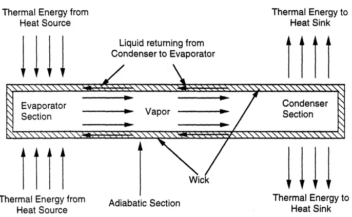
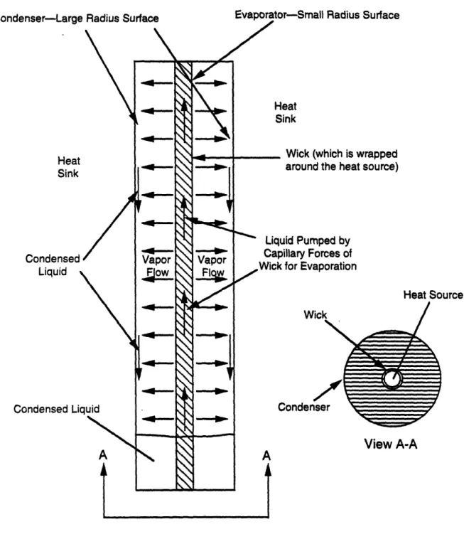
2.5 Axial Heat Pipes5
Perhaps the best known passive temperature control device is the heat pipe (see Figure
2.5). It is comprised of an enclosed container (which is usually cylindrical in shape) which
contains a wick and a working fluid. One end of the cylindrical container is the evaporator section,
the other end is the condenser section. In between the evaporator section and the condenser section
is the adiabatic section. The heat pipe functions as follows.
Thermal energy is introduced at the evaporator section. This thermal energy is absorbed by
the working fluid inside the evaporator section and the fluid is vaporized. This creates an axial
vapor pressure gradient which causes the vapor to flow from the evaporator section to the
condenser section. At the condenser section, the vapor condenses, releasing thermal energy and
converting back to liquid. The liquid is then pumped by the wick, via capillary action, back to the
evaporator section. The temperature range within which the heat pipe functions is determined by
the working fluid. The higher the boiling point of the working fluid, the higher the working
temperature range of the heat pipe. It is thus the selection of the working fluid which determines
when the heat pipe turns on and when it turns off.
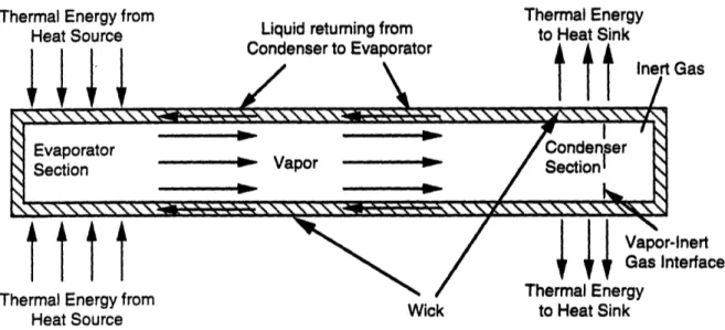
The temperature range over which a heat pipe with a particular fluid functions can be
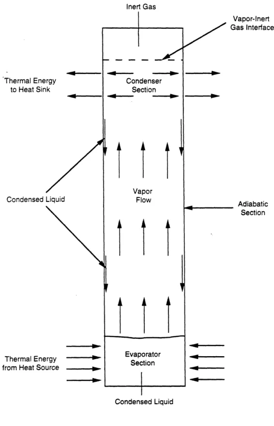
modified in several ways, although virtually all the methods involve utilizing a noncondensable,
inert gas. The simplest method is merely to introduce a noncondensable, inert gas into the heat
pipe in the condenser section with no modification in the physical geometry of the heat pipe.
Visual observations and temperature measurements show that the working fluid vapor and the
noncondensable, inert gas remain, for the most part, segregated, and that a definitive interface
exists between them no matter what the orientation of the heat pipe. There is some diffusion of the
vapor into the inert gas, but it is only a minimal amount. Thus, the active condenser length varies
Thermal Energy from Heat Source
Liquid returning from Condenser to Evaporator
,/
Thermal Energy to Heat Sink
Thermal Energy from
Heat Source
I
Wick Adiabatic Section111
Thermal Energy to Heat SinkFigure 2.5. Axial Heat Pipe
71w \11\z \I rl - 1\1\ I I I I I I
Evaporator
Vapor
CondenserSection
VapSection
~
1 :1
T 7 T
in the heat source. An increase in evaporator temperature causes an increase in vapor pressure of
the working fluid, which causes the gas to compress into a small volume, releasing a larger
amount of active condenser length for heat rejection (see Figure 2.6). Conversely, a drop in
evaporator temperature results in a lower vapor pressure, which allows the gas to expand, shutting
off active condenser surface area (see Figure 2.7). Thus for a given amount of noncondensible,
inert gas and a constant heat-sink temperature, the position of the gas/vapor interface is a function
of the thermal energy being transported by the working fluid vapor. Hence, since the presence of
the gas raises the lower limit at which the temperature of the heat pipe turns on (i.e., becomes
thermally conductive) without altering the upper temperature limit of operation (at which wick
dry-out occurs), suitable positioning of the gas/vapor interface can be used to control, within close
limits, the temperature of the heat source (which is in contact with the evaporator section of the
heat pipe).
However, one major drawback to this type of heat pipe is that the effective length of the
condenser section is reduced with the presence of an inert gas. Indeed, no matter how hot the
evaporator section becomes, a portion of the condenser section is always blocked off by the inert
gas (with the exception of the small amount of vapor that diffuses into the inert gas.) This then
results in a decrease in the rate of thermal energy transport by the heat pipe. One solution put forth
to remedy this problem is to add a rigid wall reservoir downstream of the condenser section (see
Figures 2.8 and 2.9). This reservoir provides a cavity for the inert gas to occupy as the vapor
pressure increases due to the increase in heat source temperature. Hence, at the maximum
operating temperature of the heat pipe, the maximum thermal energy transport rate of the heat pipe
is realized. The reservoir area must be lined with wick material like the rest of the heat pipe to
transport back to the evaporator section any working fluid which diffuses (in vapor form) into the
reservoir area and condenses. This type of heat pipe also provides more precise control of the
heat-source temperature than the gas-loaded heat pipe without a reservoir, since, for the same mass
of gas, the change in compressibility of the gas with respect to temperature is greater with the
larger volume.
Thermal Energy from
Heat Source
I 1I r I
Liquid returning from
Condenser to Evaporator ,/ Thermal Energy to Heat Sink
tnert
Gas 1 1 & 1Thermal Energy from
Heat Source Wick
N
Vapor-InertGas Interface Thermal Energy
to Heat Sink
Figure 2.6. Axial Heat Pipe with Inert Gas in On-Mode
Thermal Energy from
Heat Source
Inert Gas
I
Vapor-inert Gas Interface Thermal Energy from
Heat Source Wick
Figure 2.7. Axial Heat Pipe with Inert Gas in Off-Mode
'%, No --a"- ~I' I
Evaporator "- Condenser
Section Vapor Section
via; ; ;~ I I Evaporator Condenser ~'Section Vapor Section Section````````````L````````````S`ectio`n`` I.,.``````xk```````````~~````
1111
Thermal Energy from Heat Source
llr
Liquid returning from Condenser to Evaporator
Thermal Energy to Heat Sink
I & I
Thermal Energy
from Heat Source Wick
I + r+
Thermal Energy to Heat Sink
Vapor-Inert Gas Interface
Figure 2.8. Axial Heat Pipe with Inert Gas and Rigid-Wall Reservoir in On-Mode.
Rigid-Wall Reservoir is an Extension of the Condenser Section
Thermal Energy from Heat Source
+4Flr
Inert Gas
~~~~~~~ii ii/ i· i..
/Wick
Wick
1ttt
Thermal Energy from Heat Source
Vapor-Inert Gas Interface
Figure 2.9. Axial Heat Pipe with Inert Gas and Rigid-Wall Reservoir in Off-Mode
Inert Gas in
Rigid-Wall Reservoir
Evaporator _ Condenser
Section Vapor Section
26 -/ 7 7 1X, L
\\\\\\'\
\\ \\ I S\\^\S"N\\\\\\\\x\X
Evaporator Condenser
Section Vapor Section
I s
~,,.'..'..'...'x',..'..xSx,',.xSx,~,~',.'..._xS'..~',. "L'xxx'..',:',.X '_ ',.xx'..X'k\,.% ¥xxL xxx. xxx.i
Another variation of this type of heat pipe is a reservoir comprised of bellows. The
bellows allow control of the inert gas volume. They expand, increasing the reservoir's length, as
the vapor pressure increases. (due to the increasing temperature of the heat source) and contract as
the temperature of the heat source decreases (see Figures 2.10 and 2.11). This variation in
reservoir length with the heat source temperature, coupled with the compressibility of the gas,
allows even greater precision in controlling the temperature of the heat source than the heat pipe
with a fixed rigid wall reservoir. The only disadvantage of this kind of heat pipe over a heat pipe
with a fixed-wall reservoir is that the bellows add extra structural complexity to the heat pipe.
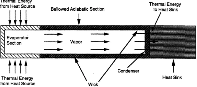
Heat pipes have also been constructed in which the adiabatic section of the heat pipe is
comprised of bellows (see Figures 2.12 and 2.13). For this type of heat pipe, no inert gas or
reservoir is present, and the condenser section is the flat face of the heat pipe opposite the
evaporator section. The outside face of the condenser has a low emissivity. At a predetermined
temperature of the heat source, the adiabatic section expands, bringing the condenser section into
contact with a heat sink. As long as the heat source is at or above this predetermined temperature it
remains in contact with the heat sink. Heat source and heat sink are thermally decoupled when the
source temperature falls below this predetermined temperature, causing contraction of the bellows.
Each of the forms of heat pipe described above are non-feedback heat pipes. They operate
on the principle that the thermal coupling between the heat source and the evaporator section of the
heat pipe is strong. Hence, if the thermal impedance between the heat source and the heat pipe's
evaporator section is large, control of the heat source temperature will, at best, be poor. The
development of feedback-controlled heat pipes has enabled precise temperature control of the heat
source to be obtained. Two forms of feedback control are feasible: active (electrical) and passive
(mechanical).
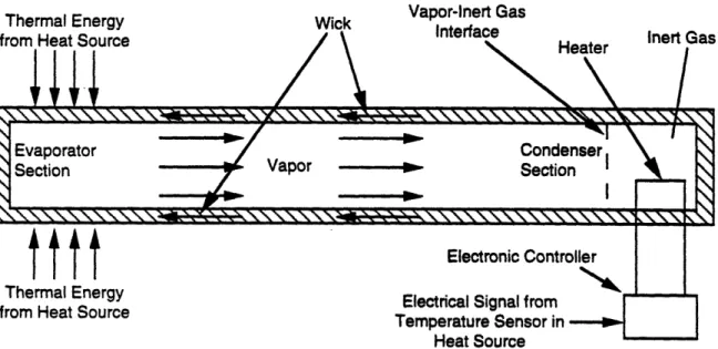
The electric feedback controlled heat pipe consists of a temperature sensor, electronic
controller, and a heat pipe with a heated reservoir containing inert gas (see Figures 2.14 and 2.15).
Internal or external heaters are used to provide thermal energy to the reservoir. Heating the inert
Thermal Energy from Heat Source
l4+
Liquid returning from Condenser to Evaporator
0/\
Thermal Energy to Heat Sink Inert Gas in Bellowed-Wall ReservoirEvaporator Vapor o C Condenser
Section Section
a /I
gtt Thermal Energy from Heat Source
Wick
Vapor-Inert
4+44
I Gas Interface Thermal Energyto Heat Sink
Figure 2.10. Axial Heat Pipe with Inert Gas and Bellowed-Wall Reservoir in On-Mode
Thermal Energy from Heat Source
Evaporator Vapor Condenser
I
Section Section
~xxxxxxxxxxx\xx,_x xxx_-.\ x-x-\,,._q,,
N"
1 11
Thermal Energy from Heat Source
Vapor-Inert
Gas Interface
Wick
Thermal Energy from Heat Source
1/11
I
Bellowed Adiabatic Section
Thermal Energy to Heat Sink / Evaporator Section
tttt
Thermal Energy from Heat SourceCondenser
T
Heat Sink Wick
Figure 2.12. Axial Heat Pipe with Bellowed Adiabatic Section in On-Mode
Thermal Energy from Heat Source
111
Bellowed Adiabatic Section
Condenser--outside surface
has low emissivity
/ Evaporator Vp Section Vapor
>
s
|
I~~~~~~~~~~~~~--ttt
Thermal Energy from Heat SourceHeat Sink
Wick
Figure 2.13. Axial Heat Pipe with Bellowed Adiabatic Section in Off-Mode . . .
- - - -
Thermal Energy from Heat Source
1111
Wick Vapor-Inert GasInterface
~~~~~~~~~~
tttt
Thermal Energy from Heat Source
Electronic Controller
N% r
tlectncal Slgnal rom
Temperature Sensor in
Heat Source
Figure 2.14. Axial Heat Pipe with Inert Gas and Temperature Controlled Rigid-Wall Reservoir. Heater is off and Heat Pipe is in On-Mode.
Thermal Energy from Heat Source
+8+1
Wick Vapor-Inert Gas
Interface Heater Inert Gas
Heate
/
tttt
Thermal Energy from Heat Source
Electronic Controller
- -_.
_.- ..
N 1
tlectrical ignal rom
Temperature Sensor in Heat Source
Figure 2.15. Axial Heat Pipe with Inert Gas and Temperature Controlled Rigid-Wall Reservoir. Heater is on and Heat Pipe is in Off-Mode.
33
eater
Evaporator Condenser
Section Cdeond oVapor Ir
Inert Gas
/
SEvaporator Sectiondenser
Section / Vapor ISection
Eltic.
I
W I~~~,
Z
'52
Z
s S.m
-hence, reducing thermal energy transport from the heat source. Similarly, allowing the gas to cool
increases the amount of condenser surface available to the vapor and, hence, increases thermal
energy transport from the heat source. Thus, by using a temperature sensing device at the heat
source, and connecting this via a controller to the heater at the reservoir, the reservoir temperature
can be regulated so that precise control of the vapor-inert gas interface occurs, maintaining the
desired source temperature within precise bounds.
The mechanical feedback control of a heat pipe involves the use of a bellowed-hollow-wall
reservoir and a sensing bulb located adjacent to the heat source (see Figures 2.16 and 2.17.). The
cavity in the wall of the reservoir contains an auxiliary fluid, usually an incompressible liquid, and
is connected to the sensory bulb by a capillary tube. Variations in the source temperature will
cause a change in the pressure of the auxiliary fluid, resulting in a displacement of the bellows.
This displacement causes the reservoir volume to change and, thus, the location of the vapor-inert
gas interface. By relating the displacement of the bellows and, therefore, the vapor-gas interface in
the heat pipe, to the temperature of the heat source, a feedback controlled system which regulates
the heat-source temperature is obtained.
Comparing the active feedback control (electrical) with the passive feedback control
(mechanical), better temperature control of the heat source is obtained using the active feedback
control system. In the active system, the location of the vapor-inert gas interface can be more
precisely controlled with the heater. However, with the passive feedback control system, there are
fewer components, and they are exposed to less severe conditions (i.e., they do not get hot).
Consequently, there is less likelihood of system failure. Thus, when selecting a temperature
control system, temperature control capability must be weighed against system reliability.
All the control methods discussed above use a vapor/gas interface to vary the heat
condenser area available for heat rejection from the heat pipe. Other techniques involving liquid
inventory control, vapor flow control, and wick modification are also available.
For heat pipes employing liquid inventory control, it can be achieved in two different ways.
One method is to remove and reintroduce the working fluid as needed. Specifically, as the
0) a) o r yu E
I
a E = ° a--ca o E 0 H ) ° o 00
0 i. 0 to 0. c C)3 c m. ci LZI3: t0 *0 C -6 a)pa: a I , I 0 1 CC' C) .0 co 0 o 0E O C o. O ) o .) 0 C.) -0 o, 0) s: 0. 3 t.) ._ a) C
n
0) -gc ) Eworking fluid condenses at the condenser section, it is removed from the heat pipe via an exit port
located at the lowest point of the condenser section (see Figure 2.18). This working fluid is then
recirculated into the heat pipe in discrete quantities by vapor bubble injection under the control of a
heater which monitors the temperature of the heat source. If no fluid is injected into the heat pipe,
the thermal conductance of the heat pipe will decrease as the condensate is removed. If fluid is
injected into the heat pipe, thermal conductance will increase as fluid is supplied to the heat pipe.
Another way of achieving liquid inventory control is to manufacture a heat pipe with a
bendable adiabatic section (see Figure 2.19). The amount of curvature in the bendable adiabatic
section controls how much liquid returns to the evaporator section of the heat pipe. (The exact
physical mechanism is that the static pressure head is increased due to the curvature by creating a
longer return path from the condenser to the evaporator for the working fluid. The wick is
designed such that the capillary pressure is less than the maximum static pressure head that can be
imposed.) As returning liquid condensate is trapped in the center of the deformed tube, less liquid
is available for evaporation in the evaporator. This results in a low liquid level that saturates only a
portion of the evaporator wick, which yields a high heat pipe thermalimpedance. If the heat pipe
bendable section is deformed so that all the working fluid is completely trapped in the bendable
portion, no liquid is available in the evaporator, and, hence, the heat pipe is completely off (i.e., no
thermal energy is transported from the heat source). An external device linked to a heat source
temperature sensor controls the amount of bend in the heat pipe, and thus the heat transfer rate of
the heat pipe.
Concerning vapor flow control, it can be achieved using an electronic throttle valve located
in the adiabatic section of the heat pipe (see Figure 2.20). A heat source temperature sensor and an
electronic controller adjust the throttle valve aperature to control the flow of vapor through the pipe.
Hence, to decrease the thermal conductance of the heat pipe, the throttle valve aperature is
decreased. Conversely, to increase the heat pipe conductance, the throttle valve aperature is
a) .' c (1) LL -ra
I
a,) w-0) a) c w LLJ a, H © Oo-o 0u
e: 0 o-_ ._*l c .N ._ -. C) u x o .;p "o a) lo to 3 So 3- 0) E0 a7:
IU 0 a) H: U, 0) a, a) ._o .2C.) u 0 Ca . L-3 .0 39 0 c0 O: C ) on
=
mi )
- E a - 0 - a Co m E ' > 0) 0 / %--o _ o _r_/ , W CE C :nY U tV I. a) 0 S--0 -a cn 0 Cl) o E ""-t
c., C.)6
._) c E , 2 cC Ev . uJ a CI-Lastly, heat pipe control can be achieved by wick modification. Thus far, two different
ways of wick modification have achieved successful results. One method involves using a wick
material which shrinks as its temperature decreases and expands as its temperature increases. Half
the axial length- of the heat pipe, from the evaporator section to the midpoint of the adiabatic
section, utilizes the expanding/contracting wick material. The other axial half of the heat pipe has
wick material which maintains a constant axial length (see Figure 2.21). Thus, as the heat source
cools off, the expanding/contracting wick material contracts, creating a discontinuity in the wick
return path from the condenser to the evaporator section for the working fluid and, hence, turning
the heat pipe off. Conversely, as the heat source becomes too hot, the wick material expands
completing the wick return path for the working fluids and, hence, turning the heat pipe on. This
expanding/contracting wick material has been developed by Hitachi.
The other method of achieving heat pipe control by wick modification also involves using
two different wick materials which are separated to turn off the heat pipe, and brought back into
contact with one another to turn on the heat pipe. However, the method of creating and removing
the discontinuity in the pumping path of the liquid is different. Specifically, the wick material
lining the heat pipe from the evaporator section to the midpoint of the adiabatic section is
comprised of magnetic material, and the other axial half of the heat pipe is lined with nonmagnetic
wick material (see Figure 2.22). An electromagnet is positioned at the point of contact between the
two different wick materials (i.e., at the adiabatic section midpoint.) The electromagnet is
interfaced with an electronic controller and a temperature sensing unit situated at the heat source.
Hence, when the heat source becomes too hot, the electromagnet is activated and moved, bringing
into contact at the adiabatic section midpoint the magnetic wick with the nonmagnetic wick.
Conversely, when the heat source is at or below its proper temperature, the electromagnetic is used
to created a discontinuity at the interfacing point of the two wicks, turning off the heat pipe.
Thus, the heat pipes discussed above represent the major types of axial heat pipes in
existence today. They are thermal switches that can be used over a very wide temperature range,
from low, cryogenic temperatures (starting from 1K), to molten metal temperatures
e _ _____a
r
-C~- _____ cZ a . -16 J
5
0 C q1 ca, Q)SI--~on
. c ci 0 Q)2-
C
- I) CC SL E · ._>1 (D c r m _______ C E 0)0
--W-
=
cI
Et1t
E W t-c C LU I-v ._ C E C oz
2 0 CI w m Cu u ._ ._u ._o CZI ._9a., et u x 3 1. C C) 0 )3
D _-2 c cn E a-o
WLzE
0 m 03 en E -2 w O.04----·
rC0---
.04----3,000K). Needless to say, they have found innumerable applications. Indeed, so successful has
been this concept of thermal energy transport by vapor convection of latent heat, that variations of
the axial heat pipe concept have arisen.
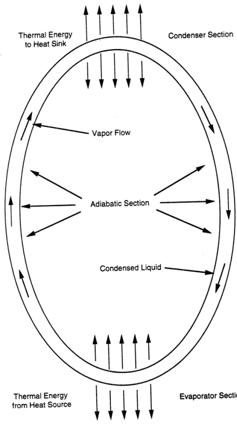
2.6 Radial Heat Pipe6
One variation that has proven successful is the radial heat pipe. It is similar to the axial heat
pipe in that it is comprised of a container, a wick, and a working fluid. However, its
cross-sectional configuration is annular, not circular and its direction of heat transfer is radial, not axial
(see Figure 2.23). The evaporator section is usually the small radius surface of the annulus,
although it can be the larger radius surface as well. Whichever surface it is, the other surface
comprises the condenser section of the radial heat pipe. A wick lines the evaporator section. (If
the evaporation section is the smaller-radius surface of the annulus, and the radial heat pipe will not
be operating in a directly vertical, position, then care must be taken to ensure that the wick extends
far enough radially at some circumferential point to contact and absorb the condensate.) As with
the axial heat pipe, thermal energy is absorbed at the evaporation section and released at the
condenser section. However, as mentioned above, the direction of vapor travel (and hence heat
transfer) is radial, not axial.
2.7 Other Types of Heat Pipes5
Other types of heat pipes are electro-hydrodynamic heat pipes, magnetohydrodynamic heat
pipes, and osmotic heat pipes. These devices also operate on the evaporation/condensation
principle, with the difference arising in the method of condensate return. Electrohydrodynamic
heat pipes use electrostatic volume forces to return the condensate to the evaporator section;
magnetohydrodynamic heat pipes use magnetic volume forces, and osmotic heat pipes use
Evaporator-Small Radius Surface Heat Sink Condensed Liquid Condensed Li eat ;ink
Wick (which is wrapped around the heat source)
uid Pumped by fillary Forces of for Evaporation Heat Source ;ond View A-A
Figure 2.23. Radial Heat Pipe r~nneiancar-I armp Rnriimfitilrfano_§ ._ww .__ _lI yW
2.8 Thermal Svphon,8,7 9
Another variation of the heat pipe concept is the thermal syphon. There are two different
kinds of thermal syphons. One is basically an axial heat pipe without a wick (Figure 2.24), while
the other is a loop without a wick (Figure 2.25). For both types of thermal syphons, like the heat
pipes, the section between the evaporator and condenser is insulated. However, unlike the heat
pipes, since no wick is present, the condenser section must be at a higher elevation than the
evaporator section to return the working fluid from the condenser to the evaporator. Thermal
syphons would be used instead of heat pipes in situations where the working fluid chosen is
reactive with all wick materials available.
A third variation of the heat pipe concepts discussed earlier is the controllable thermal
syphon. This device is similar to the axial-like thermal syphon described above, except that an
noncondensible, inert gas is also present in the device (see Figure 2.26). Like the gas buffered heat
pipes discussed earlier, the inert gas prevents any heat transfer by the thermal syphon until the
vapor pressure of the working fluid is high enough to push the gas/vapor interface into the
condenser region, allowing exposure of the working fluid vapor to the condenser walls. Suitable
initial positioning of the gas/vapor interface yields the desired temperature control of the heat
source. It should be noted that this gas-buffered thermal syphon is also known in the heat transfer
field as a high conductance vapor thermal switch.
2.9 Bistable Passive Thermal Switch1 0
Another kind of thermal switch discovered in the literature survey is the bistable passive
thermal switch. The bistable passive thermal switch can be visualized as a metallic cylindrical shell
with two pipes running axially through it and linked to an accumulator (see Figure 2.27). One of
the pipes runs axially along the bottom of the shell, while the other runs axially along the top of the
shell. The lower pipe has hot fluid or gas flowing through it that acquired its thermal energy from
a heat source. The upper pipe has cold fluid or gas flowing through it that leads to a heat sink such
Thermal E to Heat , Condensed Li Thermal Eni from Heat Sc armal Energy Heat Sink Adiabatic Section Thermal Energy om Heat Source Condensed Liquid
Condenser Section
Thermal Energy from Heat Source
Figure 2.25. Loop Thermal Syphon
Inert Gas
Thermal Energy
to Heat Sink
Condensed Liquid
Thermal Energy from Heat Source
Vapor-Inert
-.*
Rae -. -nt -·I---- ~ B-- Condenser Section Vapor Flow II
I
Evaporator Section Condensed LiquidFigure 2.26. Thermal Syphon with Inert Gas
'4 Adiabatic Section 1 _ I '000 ." *- JCI III vI 1.t W 40---- - Oa---- 09----1-0
Cylindrical Shell Completely Filled Na Con\ I'l Off Mode Accumulator On Mode
Figure 2.27. Bistable Passive Thermal Switch Without Air in the Cylindrical Shell
lter
>tbc
Accumulator
water. Thus, by controlling the shell pressure, the bistable passive thermal switch can be switched
on or off. In the off mode the water in the shell is not boiling and transfers only a minimal amount
of thermal energy from the hot pipe to the cold pipe via natural circulation. However, during the
on mode, the water in the shell boils on the lower pipe (which, as mentioned above, is carrying
fluid heated by a heat source), displaces excess water into the accumulator, and condenses steam
on the upper pipe (which is carrying cold fluid leading to a heat sink). Heat transfer analysis as
well as experimental data indicate two orders of magnitude difference in the heat transfer rate of the
thermal switch from its on mode to its off mode.
A variation of the above thermal switch is the inclusion of air in the shell (see Figure 2.28).
Specifically, the shell is only partially filled with water with the remaining volume filled with air.
Thus, the cold pipe is not submerged in water. This results in a higher thermal resistance in the off
mode than the previous design because of the high thermal resistance of the air space. Also, a
smaller accumulator can be used. However, the presence of noncondensibles also increases
thermal resistance in the on mode. Hence, which thermal switch design one should choose is
determined by off-mode heat loss allowance and on-mode heat transfer requirements.
2.10 Temperature-Initiated Passive Cooling System1 1
The last type of thermal switch discovered in the literature survey is the
Temperature-Initiated Passive Cooling System (TIPACS). Shown in Figure 2.29, it was conceived and
developed at Oak Ridge National Laboratory and consists of a heat-transfer system (HTS) and a
temperature-control system (TCS). The following, partially taken from a paper written by the
inventors of the device, C.W. Forsberg and J.C. Conklin, gives a description of the principles of
operation of the device as well as its physical characteristics.
As mentioned above, TIPACS consists of two subsystems: a heat-transfer system (HTS)
and a temperature-control system (TCS). The HTS is a single-phase, sealed, natural-circulation
system that uses a heat-transfer fluid operating just above its vapor-liquid critical point. (The
nulator ;onvection Currents Off Mode Condense nulator On Mode
Figure 2.28. Bistable Passive Thermal Switch With Air in the Cylindrical Shell Natu
LAJ wz Iw W O , I t Q - L.
cz
-W z I-W < I Az w-z
0oFw
w c c O 0: 0 E .M O U CT, cu '0 .) la. L. E 0I a.) cu C) 30-i4 I I iI
I u I, 4 Q I C c) /M ! -I IIrl
I I I I I I I 0414* I I I I I I...liquid phase no longer exists and only a supercritical-phase exists.) Thermal energy generated by
the heat source is cooled by the internal TIPACS heat exchanger. The warm, lower-density
supercritical fluid inside the internal heat exchanger flows upward to an air-cooled external heat
exchanger. The supercritical fluid is cooled as its heat is transferred to the environment through the
external heat exchanger, and the cooler, higher-density fluid flows downward back to the internal
heat exchanger.
The TCS is the insulated piping and apparatus above the heat exchangers. It is a passive
device that blocks the flow of fluid if the heat source temperature drops below the vapor-liquid
critical point, and allows the flow of fluid if the heat source temperature is above the critical
temperature of the working fluid and above the heat sink temperature. It accomplishes this via its
piping geometry. Specifically, below the critical-point temperature the fluid in the system is partly
liquid and partly gas, with gas-liquid interfaces in the insulated piping above the heat exchangers
(i.e., in the TCS). Thus, it is this gas zone in the TCS at the top of TIPACS that prevents the liquid
from flowing around the natural-circulation heat transfer loop. However, as the temperature
approaches the critical point, (1) the liquid expands to fill the vapor space, (2) the two-phase
system then converts to a single-phase supercritical system, (3) the vapor lock is eliminated, and
(4), if the heat source temperature is above the heat sink temperature, the single-phase HTS starts
up. The HTS will not start up if the heat sink temperature exceeds the heat source temperature
because the external heat exchanger is at a higher elevation than the internal heat exchanger. (In
this situation, hot, low-density fluid fills the TCS, while colder, higher-density fluid settles to the
bottom of the HTS, creating a dynamically stable fluid configuration. Hence, no fluid circulation
occurs.)
Note that HTS performance is maximized when (a) the fluid pressure is just above the
fluid's critical pressure and (b) the operating temperature range from hot to cold is just above the
fluid's critical temperature. This phenomenon is a direct result of the thermodynamic and
transport properties of fluids near their critical points. (Four physical properties primarily