HAL Id: hal-01646203
https://hal.archives-ouvertes.fr/hal-01646203
Submitted on 3 Jan 2019
HAL is a multi-disciplinary open access
archive for the deposit and dissemination of
sci-entific research documents, whether they are
pub-lished or not. The documents may come from
teaching and research institutions in France or
abroad, or from public or private research centers.
L’archive ouverte pluridisciplinaire HAL, est
destinée au dépôt et à la diffusion de documents
scientifiques de niveau recherche, publiés ou non,
émanant des établissements d’enseignement et de
recherche français ou étrangers, des laboratoires
publics ou privés.
Ronan German, Ali Sari, Olivier Briat, Jean-Michel Vinassa, Pascal Venet
To cite this version:
Ronan German, Ali Sari, Olivier Briat, Jean-Michel Vinassa, Pascal Venet. Impact of Voltage Resets
on Supercapacitors Aging. IEEE Transactions on Industrial Electronics, Institute of Electrical and
Electronics Engineers, 2016, 63 (12), pp.7703 - 7711. �10.1109/TIE.2016.2594786�. �hal-01646203�
Abstract— Compared to Li-ion batteries, supercapacitors (SCs) boast longer lifespan, higher power density, and wider operational temperature range. Nevertheless, SCs are expensive (almost 40 times more expensive per Wh than Li-ion batteries).
SCs ageing is critical. Two types of ageing tests are usually performed. Floating ageing tests apply constant constraints (voltage and temperature), and cycling ageing tests apply multiple charges and discharges.
We focus our study on floating ageing (corresponding for instance to parking mode for electrical vehicles (95% of the time) or uninterruptible power supplies (UPSs) when they are not solicited (quite all the time)). All results in literature conclude that voltage level is an acceleration factor for supercapacitor ageing. According to literature, it would be interesting to discharge totally SCs when they are not in active use (i.e. when the UPSs or vehicles are turned off) to improve their lifespan.
Contrary to literature forecasts (i.e. lower voltage increases lifespan of supercapacitor) the results obtained in this article by alternating voltage resets (0 V, 60°C) and floating ageing (2.8 V, 60 °C) show that discharging even very few times the supercapacitors shortens their lifespan drastically. Physical interpretations are presented to explain ageing increase with voltage resets.
Index Terms— Supercapacitors, Electrochemical Double Layer Capacitors, Ultracapacitors, voltage reset, deep discharge, ageing.
I. INTRODUCTION
NERGY storage systems (ESSs) are becoming more and more important in automotive industry because of legislative pressure on personal vehicles, airplanes fuel consumption and greenhouse gases emissions. Capacitors,
Manuscript received January 25, 2016; revised April 20, 2016 and June 2, 2016; accepted June 18, 2016. This work was supported in part by the French National Agency for Research (ANR).
R. German, A. Sari and P. Venet are with the University of Lyon, Université Lyon 1, laboratoire Ampère UMR CNRS 5005, F-69622, Villeurbanne Cedex, France (e-mail : [email protected] for A. Sari and P. Venet and [email protected] for R. German).
O. Briat and J.-M. Vinassa are with the Univ. Bordeaux, IMS, UMR
5218 CNRS, F-33400, Talence, France (e-mail :
supercapacitors and batteries are the most common ESSs used nowadays. Supercapacitors (SCs) [1][2], also called Electrochemical Double Layer Capacitors [3][4] or ultracapacitors [5], can deliver higher power than batteries in a wider temperature range [1]. The energy storage mechanism of SCs is based on the double layer effect and does not have chemical transformations like batteries. Consequently the cyclability and the power density of SCs is better than batteries [6]. This makes SCs an attractive ESS for security applications (such as energy storage device for opening the emergency doors of Airbus A380) or peak power smoothing [7] [8]. SCs can also be used for tramway [9] [10] and electrical traction systems such as hybrid or electric vehicles (HEVs) [12]. They can be used as a single ESS or in combination with other ESSs [13] like batteries [14] or fuel cells [15].
For any ESS, ageing has to be taken into account for integration. Currently ESSs ageing is studied with two different approaches. The first approach consists in performing accelerated ageing tests with various constraints [16][17] which can be close to the real use of ESSs [17]. The goals of this approach are to identify the main impact factors on ESSs ageing, to give physical meaning to ageing mechanisms [18] and to build ageing laws from experiments [19]. In such approach a maximum of offline tests are performed to get detailed information. The second approach is more focused on fault detection, adaptive estimators [20] [21] and data driven methods such as neural networks [22]. Tests are focused on one key measure linked to the state of health (SOH) of ESSs. Such approach aims to improve the battery management system (BMS) functions (SOH estimation…). We can notice that this second approach can also use the first approach as a learning database [22]. For the second approach simplicity and calculation time are preferred to a detailed analysis of ageing processes.
This paper is focused on the first approach. The selected ESS will be SCs. The aim is to show the ageing impact of periodically setting the voltage down to the lower limit (0 V for a SC). According to existing literature [23] [24] [25], lowering the voltage will increase the lifetime of SCs. The contribution of this work is to show by accelerated ageing tests that periodically fully discharging the SCs is increasing the ageing rate. Physical interpretations are also given. Periodic characterizations are performed with electrochemical
Impact of Voltage Resets on
Supercapacitors Ageing
Ronan German, Ali Sari, Member, IEEE, Olivier Briat, Jean-Michel Vinassa, Member, IEEE,
Pascal Venet, Member, IEEE.
impedance spectroscopy (EIS) technique. EIS is widely used as a nondestructive control method in laboratories to study SC ageing and allows observation and understanding of the evolution of the state of health of SCs [26]. In this article we test with EIS 3000F SCs from 3 different manufacturers built with the most widespread technology (carbon/carbon electrodes and organic acetonitrile/TEABF4 electrolyte [27])
to have a representative sample of commercial SCs.
As the lifespan of SCs is relatively long under normal use conditions (10 years of lifespan at 25°C, 2.7 V for the tested components [27]), accelerated ageing tests are required to get results in a reasonable delay. Two types of accelerated ageing tests are widely used in literature: the first type (cycling ageing test) consists in a succession of charging and discharging at high current rate. The second type (floating ageing) is performed at fixed voltage and temperature.
In this paper, floating ageing of SCs is taken as the reference test. To test if the SCs lifespan can be improved by setting their voltage to zero during HEV parking phase (which corresponds to a total discharge of the SCs when the HEV is parked), we will perform three tests. Firstly, we test the effect of floating ageing on 9 SCs, and then through 2 different experimental tests apply voltage resets on a new batch of 10 SCs. The next section presents the bases for understanding SCs ageing, which provides a background to introduce experimental protocol in section III and a basis for interpretation of experimental results in section IV.
II. SCS AGEING IN LITERATURE A. Tested SCs constitution and performances
Fig. 1 presents the physical principle behind double layer SCs. SCs is mainly composed of two porous electrodes immersed in a liquid electrolyte. The interface between electrodes and electrolyte is the key zone in which energy is stored by double layer effect (one ionic charge facing one electronic opposite charge) and maximized by the porosity of electrodes. The two electrodes are prevented from electrical short circuit by a perforated membrane called separator, which allows ions to circulate in the electrolyte. Collectors connect electrodes and external circuit.
Nowadays, the most prevalent electrolyte/electrode technology for high capacitance SCs uses Acetonitrile (ACN) as electrolyte solvent and tetraethylammonium tetrafluoroborate ET4NBF4 (also called TEABF4) as ionic salt.
ACN appears to be the best compromise between high conductivity, high relative dielectric constant (εR=37) and low
freezing point (around -40 °C) [27] although it is classified as hazardous and flammable. ET4NBF4 crystallization
temperature is also very low and permits SC to function normally for temperatures between -30°C and 65 °C [27]). The electrodes are built with a porous material to maximize the contact surface between electrode and electrolyte.
‐
+
‐
‐
‐
C ollec tor E lec tr od e + ∆USC C ollec tor El ec tr od e-‐
+
Separator+
‐
Solvated anions and cations+
+
+
Fig. 1 Physical principle for energy storage in SCs [26].
TABLEI
ELECTRIC CHARACTERISTICS OF DIFFERENT MANUFACTURER
ACETONITRILE/ACTIVE CARBON COMMERCIAL 3000FSCS.
Electrode Activated Carbon
Electrolyte Acetonitrile
Capacitance 3000 F
Manufacturer A, B, C
Equivalent Series Resistance ESR (mΩ) 0.20< ESR< 0.29
Nominal voltage UN (V) 2.7< UN< 2.8
Limit impulse current <1s (A) ≈2000A
Max operating temperature Tmax (°C) 60<Tmax< 65
Cell Weigth M (g) 510<M<650 Mass energy WM (kJ/kg) 17.8< WM<21.5 10-2 10-1 100 101 102 0 1 2 3 frequency (Hz) C ap ac ita nc e (k F) LF HF Constant capacitance zone
Fig. 2 Evolution of capacitance of SC with frequency [26].
Activated carbon [28], which is relatively abundant and cheap to produce, (it can be produced from nutshells [29]), is used to build highly porous electrodes (the contact surface between electrode and electrolyte is around 2000 m² per gram of activated carbon [28]). All the tested SCs are manufactured with the same technology and have similar performances as shown in Table I.
B. SCs particularities concerning energy storage
As there is no dielectric film, the distance (d) between ions and opposite sign electric charges is very short. At very low frequency (LF) SC electrodes can be considered as flat electrodes, because ions storage time constant in the electrode porosity is much smaller than the electric signal period. Then at LF the expression of SC electrode capacitance is given by (1). R 0 dl S C d (1)
where ε0 is the dielectric permittivity of the vacuum. By
combining the short distance between ions and opposite sign electric charges with the high energy storage surface developed by activated carbon, SCs are able to develop capacitance up to 3000F for a mass of 0.6 kg [30].
+
+
+
+
+
Free Zone+
6 6 Electrolyte Pa ck ag ing le ng the ning T 4 1‐
‐
‐
‐
‐
USCSolid reaction products Surface functional groups Gaseous reaction products
‐
+
+ ‐
Electric positive/ negative chargesIonic positive/ negative charges
1 : Solids blocking porosity 2 : Gas in free zone 3 : Adsorbed gas in porosity 4 : Gas stored in separator 5 : Electrode cracking 6 : Partial collectors rupture
Electrode Col le ct or
‐
5‐
Pressure 2 1‐
‐ ‐
+
+
+
+
+
1 1 3Fig. 3 Causes and impacts of SC ageing and energy storage with double layer effect [26].
To get the maximum porous storage surface the pores are nanometer scale. As a consequence of the very narrow pores, the penetration of ions into the electrode pores is highly dependent on the frequency of the incoming electrical charges [31]. The higher the frequency is, the more difficult it is for ions to enter deeply in the electrode porosity. Consequently, the capacitance behavior of SC can be divided into two frequencies zones (see Fig. 2). The low frequency (LF) zone corresponds to frequencies in which ions are occupying the entire accessible interface surface between ions and electrolyte leading to a maximum constant capacitance. For higher frequencies (HF), the capacitance decreases (see Fig. 2) because the ions penetrate less deeply in the electrode porosity with increasing frequency leading to storage surface decrease. That means that SCs are only usable at low frequency contrary to film capacitors [32].
C. Ageing mechanisms for SCs
The operation to get a porous structure out of carbon is called activation. Most of the time corrosive activation species are used to create the porosity during carbonization [33]. After carbonization, electrodes are washed to remove activation species. However, no washing process is perfect. Thus, there are still some remaining species on the activated carbon electrodes [24] as depicted in Fig. 3. These species are called functional groups. Functional groups are highly reactive with electrolyte under the nominal constraints (voltage USC and
temperature T) of the SC. The zones where the ageing takes place are linked to the formation of the double layer.
As a matter of fact in the double layer zone the electric field gradient is maximum (because the opposite sign ion/ electric charges are very close in this zone) which creates the electrochemical ageing reactions between electrolyte and electrode functional groups.
The operation to get a porous structure out of carbon is called activation. Most of the time corrosive activation species are used to create the porosity during carbonization [33]. After carbonization, electrodes are washed to remove activation species. However, no washing process is perfect. Thus, there are still some remaining species on the activated carbon electrodes [24] as depicted in Fig. 3. These species are
called functional groups. Functional groups are highly reactive with electrolyte under the nominal constraints (voltage USC and temperature T) of the SC [24]. The zones
where the ageing takes place are linked to the formation of the double layer. As a matter of fact in the double layer zone the electric field gradient is maximum (because the opposite sign ion/ electric charges are very close in this zone) which creates the electrochemical ageing reactions between electrolyte and electrode functional groups. The reactions produce both solid and gaseous reaction products [24]. The solids products block the porosity of electrodes slowly (zone 1 of Fig. 3) and reduce the contact surface between electrode and electrolyte [34]. As a consequence, the SC capacitance decreases with time. The gas products have multiple possible destinations and impacts on SC ageing. When they are thermally agitated, they can reach the free zone (zone 2 of Fig. 3) and contribute to SC internal pressure increase. The gas products can also be adsorbed on electrode surface (zone 3 of Fig. 3) and consequently reduce the contact surface between electrode and electrolyte [24] (capacitance decreases). As those gases are adsorbed, they don’t participate to the SC internal pressure increase (the phenomenon of pressure is associated with the thermal agitation of gas which is characteristic of free gas, whereas adsorption corresponds to a static state). The gas products can also accumulate in the separator and block the circulation of ionic charges (zone 4 of Fig. 3).
The gases liberated in the electrolyte free zone (see zone 2 of Fig. 3) increase the internal pressure of SC, causing electrode cracks (zone 5 of Fig. 3) and SC packaging elongation), which damages the collectors (zone 6 of Fig. 3). The results of the ageing phenomena described above are reflected in the evolution of the capacitance (dependent on the contact surface between electrode and electrolyte) and the Equivalent Series Resistance (ESR is dependent on contacts and charges movement). Thus impedance of the SC is a good indicator of SC ageing [26]. Fig. 4 presents the evolution of SC impedance (ZSC) with time for 2.8 V, 60 °C floating
ageing constraints. The increase of ESR is visible with the increase of ZSC real part and the decrease of capacitance with
0.2 0.25 0.3 0.35 0.4 0 2 4 6 Real(Z SC)(m) -Im (Z SC )(m ) 0h 941h 1924h
Fig. 4 Evolution of SC impedance with ageing represented in a Nyquist plot.
II. EXPERIMENTAL PROTOCOL
During ageing tests the SCs are periodically tested by electrochemical impedance spectroscopy (EIS). Capacitance and resistance are extracted from SC impedance spectrum at 100 mHz as this frequency (f) is located in the constant capacitance zone as shown in Fig. 2. The SC capacitance at 100 mHz (C100mHz) and the SC resistance at 100 mHz
(R100mHz) are calculated by using the following expressions.
mHz 100 f mHz 100 ) SC Z Im( f 2 1 C (2) mHz 100 f SC mHz 100 Re(Z ) R (3)
C100mHz represents the energy that the SC is able to store in
LF and R100mHz represents a sum of different resistive effects
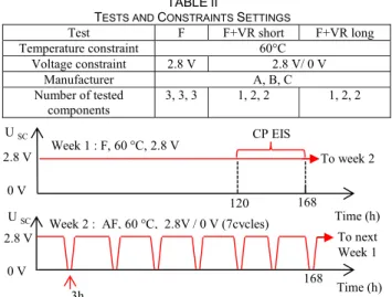
such as the conduction of electrodes, the quality of contacts between collector and electrodes, the conductivity of ions through the separator (see Fig. 3) and the difficulty for ions to penetrate into the pores. In order to investigate the impact of periodical voltage reset on SCs ageing, three accelerated ageing tests have been carried out on components from 3 manufacturers (called A, B and C because of confidentiality policy of our industrial partners) as presented in Table II. The first reset test (presented in Fig. 5) studies the impact of short and frequent voltage reset on SC ageing. The floating constraints (60°C, 2.8 V) are applied during one week (week 1) and a series of 3 hours of voltage reset by day is applied during the next week (week 2). The sequence is then repeated for 40 weeks (9 months). We call this test F+VR short. To avoid any high current effect, the charging and discharging are made at very low current for the tested SCs (1.5 A for 130 ARMS designed components [30]). The second reset test
(presented in Fig. 6) studies the effect of long voltage resets. The floating constraints (60 °C, 2.8 V) are applied during 5 weeks and then the voltage is reset for 1 week (week 6). The sequence is repeated for 40 weeks (9 months). We call this test F + VR long. The current applied for charging and discharging (1.5 A) is the same than for F + VR short test. The results of the two tests are then compared with the reference floating ageing (F) test at 60°C, 2.8 V (performed during 7 months). Table II presents the number of SCs tested by manufacturer and by ageing test. Overall, 19 high capacitance components are tested (doing more test is difficult because of price and long ageing time).
TABLEII
TESTS AND CONSTRAINTS SETTINGS
Test F F+VR short F+VR long
Temperature constraint 60°C Voltage constraint 2.8 V 2.8 V/ 0 V Manufacturer A, B, C Number of tested components 3, 3, 3 1, 2, 2 1, 2, 2 Week 1 : F, 60 °C, 2.8 V Time (h) 168 2.8 V 120 CP EIS
Week 2 : AF, 60 °C, 2.8V / 0 V (7cycles)
Time (h) 168 2.8 V U SC U SC 0 V 0 V To week 2 To next Week 1 3h
Fig. 5 Evolution of SC voltage during the floating and short voltage reset test
(F+ VR short). 5 Weeks : F, 60°C, 2.8 V Time (h) 840 2.8 V CP E IS Week 6 : 60°C, 0V Time (h) 2.8 V To week 6 U SC 0V CP E IS To next 5 Weeks : F, 60°C, 2.8 V CP E IS 168 0V
Fig. 6 Evolution of SC voltage during the floating and long voltage reset test (F + VR long). 0 2000 4000 6000 8000 100 150 200 T ime (h) R 100 m H z (% ) 0 2000 4000 6000 8000 70 80 90 100 T ime (h) C 100 m H z (% ) SC 1 SC 2 SC 3 F : 60 °C, 2,8 V Man. A
Fig. 7 Example of the reproducibility of ageing of chosen SCs for Man. A during F test.
The number of components for the tests could appear small but experimental results shows us that chosen SCs are very reproducible in the same ageing conditions as you can see for manufacturer A in Fig. 7. From Fig. 7, it can be observed that dispersion on resistance for manufacturer A is always lower than 1% and dispersion on capacitance is always lower than 2%. For other manufacturers, B and C, small dispersions are also recorded (<3% for C100mHz and
C100mHz at any ageing time). Thus, for our study, representing
floating ageing results with averaged results leads to a maximum uncertainty of +/- 1.5 % which is approximately the thickness of the drawing line in Fig. 8.
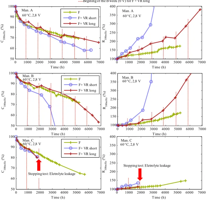
0 1000 2000 3000 4000 5000 6000 7000 100 150 200 250 300 350 400 T ime (h) R 10 0m H z (% ) 0 1000 2000 3000 4000 5000 6000 7000 50 60 70 80 90 100 T ime (h) C10 0m H z (% ) F F+ VR short F+ VR long 0 1000 2000 3000 4000 5000 6000 7000 50 60 70 80 90 100 T ime (h) C 10 0m H z (% ) F F+ VR short F+ VR long 0 1000 2000 3000 4000 5000 6000 7000 100 150 200 250 300 350 400 T ime (h) R 10 0m H z (% ) 60 °C, 2,8 V 60 °C, 2,8 V 60 °C, 2,8 V 60 °C, 2,8 V Man. A Man. A Man. C Man. C
Begining of the B week (0 V) for F + VR long
Stopping test: Eletrolyte leakage Stopping test: Eletrolyte leakage
0 1000 2000 3000 4000 5000 6000 7000 50 60 70 80 90 100 T ime (h) C10 0m H z (% ) F F+ VR short F+ VR long 0 1000 2000 3000 4000 5000 6000 7000 100 150 200 250 300 350 400 T ime (h) R 10 0m H z (% ) 60 °C, 2,8 V 60 °C, 2,8 V Man. B Man. B
Fig. 8 Evolution of C100mHz and R100mHz with and without voltage reset.
All the average floating ageing results are presented by manufacturer in Fig. 8. The results obtained for F+VR (long and short) are the same for dispersion at the beginning of the ageing test. For advanced ageing, the results are more dispersed but still acceptable (less than +/- 10% for R100mHz
and less than +/- 5 % for capacitance) for averaging. III. EXPERIMENTAL RESULTS AND INTERPRETATION
Fig. 8 presents the results of the three ageing tests on C100mHz and R100mHz. All the test results are averaged (that is
not a problem because of component reproducibility as shown in Fig. 7). The starts of the 0 V weeks for F+ VR long tests are marked by vertical dotted lines. The first effect of voltage reset is overpressure. It is clearly visible in Table III showing as example the volume increase of supercapacitors and the mass loss between the beginning and the end of the test for floating and floating + voltage resets short constraints.
TABLEIII
COMPARISON BETWEEN AVERAGE MASS LOSS AND VOLUME INCREASE OF
SCS DURING FLOATING AND FLOATING +VOLTAGE RESETS SHORT TESTS
SCs mass loss (%) SCs volume increase (%)
Test F F + VR short F F + VR short
Man. A -0.2 -1.0 +3.1 +3.7
Man. B -0.4 -1.2 +2.8 +3.8
Man. C -0.2 -4.3 +0.2 +6.4
SCs volume is increasing in both cases showing an increase of the pressure. For a defined level of pressure, mechanical safeties on the SCs body allow to release overpressure by electrolyte leakage (explaining the mass loss). Other cases of increase of resistance with pressure related electrolyte leakage can also be found in literature [18].
We can clearly notice in table III that the voltage resets lead to a higher SC deformation and a higher electrolyte
release confirming the higher pressure when voltage resets occur. As depicted in Fig. 3 the increase of SC internal pressure can only be associated with free gases (the adsorbed gasses do not contribute to pressure increase as they are in a state similar to liquid state). Thus, we can deduce that there is a great impact of voltage resets on the gases released in free zone.
Two factors can explain such a phenomenon. For instance the production of gas can be increased by voltage resets and/or the voltage resets can liberate the adsorbed gases and push them into the free zone. From the figures of R100mHz, firstly we
can also see that the increase of internal pressure is correlated to the increase of R100mHz with time. This can be explained
based on the discussion on Fig. 3. The gases liberated out of the porosity can go into the separator and in the electrolyte free zone. When gases are stored into the separator they slow down the movement of ionic charges and when gases are in the electrolyte free zone they make the pressure increase damaging the quality of connections. Thus, liberated gas lead to the high degradation rate of R100mHz.Secondly we can see
that degradation of R100mHz is more drastic in short and
frequent voltage reset than in long voltage reset. This tends to show that the duration of voltage reset is not a determinant factor for SCs ESR ageing rate, but the total number of voltage resets is a more prominent ageing factor. The more often the voltage resets are, the more the gases produced in the porosity are liberated and can accumulate in the separator and the electrolyte free zone. Again, the SCs deformations and electrolyte leakage observed in Table III confirm this overpressure implied by voltage resets. The production of gas can be increased by voltage resets, and/or the voltage resets can liberate the adsorbed gases and push them into the free zone.
For the F + VR short test capacitance decrease is significantly faster than for floating test. As capacitance is dependent on the contact surface between electrodes and electrolyte, it can be deduced that the more often the voltage resets are, the faster the porosity blockage develops (voltage resets also increase the solids production in the pores). In other words, the reactions between surface functional groups and electrolyte are aggravated by frequent voltage resets.
As those reactions produce both solids and gases [24], we can conclude that the gas and solid decomposition products are enhanced by voltage resets.
Table IV presents a comparison between the sizes of solvated electrolyte ions and different commercial activated carbon of the Pica Company [28] (named PICA I, II, III) cited as examples. The ions and solvent of tested SCs is the same ions/solvent couple that is used in manufacturer A, B and C components. However, there is no chance to know if PICA I, PICA II and PICA III are the activated carbon used by the manufacturer A, B or C, as the SCs manufactures do not communicate on their components suppliers. Anyway, those activated carbons (cited as examples) are representative of the activated carbon which can be used in the tested supercapacitors because the median pore diameter are close to the diameter of solvated ions used. The tight fit between solvated ions and median pore diameter is a key point for SC manufacturers to store the maximum energy [35].
TABLEIV
SIZE COMPARISON OF SOLVATED IONS IN SCS ELECTROLYTE [36] AND
EXAMPLES OF COMMERCIAL ACTIVATED CARBON POROSITY [28] Median solvated anion
diameter (nm)
1.30 (for ET4N+ in ACN )
Median solvated anion
diameter (nm) 1.16 (for BF4
- in ACN)
Example of commercial activated carbon
Pica I Pica II PICA III
Median pore diameter (nm) 2.32 1.96 1.08
+
++
‐ ‐ ‐ ‐ ‐ ‐ ‐ ‐ ‐ ‐ ‐ + + ++
+
+
+
+
+
+
+
‐ ‐ ‐ ‐ ‐ ‐ ‐ + + + + + + ‐ ‐ + + ++
‐ ‐+
+
+
‐ ‐ ‐ ‐ ‐+
+
+
+
+
F n°1 Voltage Reset F n°2 High electric field ageingzone Gas molecules
‐ + Ions
Fig. 9 Interpretation of the effect of voltage resets on one electrode of the SC.
We must also take into account that the activated carbon porosity is dispersed. Median pore diameter means that 50 % of pores have bigger diameter and 50% have a smaller one. That means that the porosity can go from sub-nanometer to few nanometers for a 1 nm median pore size with a Gaussian distribution. Some other activations techniques such as Carbide Derived Carbon (CDC) allow to obtain very tight pore diameter distribution [36] but they are too expensive to be widely commercialized. It is also important to take into account that pores slightly inferior to the solvated ions can nevertheless store them by removing a part of the solvation layer [37]. The energy stored into those “nanopores” is higher than in other pores because the double layer is thinner (because of the removal of one part of the solvation layer) [35][37]. Thus, although PICA III has a smaller diameter than solvated ions it could be an interesting choice for manufacturers. Thus, for any commercial activated carbon dedicated to SCs ions are very tightly fitted into the pores as represented in Fig. 9.
Fig. 9 presents an interpretation of SCs over-ageing with voltage resets. The size of the pores (diameter of aperture) for commercial SCs electrodes made of activated carbon is very close to the size of the electrolyte ions for the reasons presented in the previous paragraph. That means that the ions are very tightly fitted into the pores. Thus the repartition of ions in electrolyte may slightly differ between two successive fully charged states because of random ions “traffic jams” which block a part of porosity as shown in Fig. 9.
At first the SC is charged and maintained at constant voltage for the first floating period (F n°1). The ions are organized in a particular way into the pores but do not occupy the whole porosity because some ions are blocking the access to the bottom of the pores. The zones where ions face opposite sign charges have the highest electrical field gradient. Thus the surface groups of these zones are particularly affected by ageing. The zones of porosity which are not accessible to the ions are not affected by ageing. The produced gases are adsorbed between the ions on the electrode surface. If there is no voltage loss (i.e permanent floating ageing), the repartition of the charges stays the same and some zones of the porosity are protected from ageing. During voltage resets, a part of the ions are expelled out of the porosity dragging with them the adsorbed gas molecules.
These expelled gases then accumulate in the separator or in the electrolyte free zone of the component, as explained previously for the phenomenon of the increase of internal pressure and R100mHz of the SCs with voltage resets. When the
SCs are charged again (F n°2), the repartition of charges has changed, exposing new zones to ageing. Those new zones are very reactive because they are rich in functional groups as they were not subjected to floating ageing before. This leads to new local high speed ageing zones. The more frequent the voltage resets are, the more new high speed ageing zones are created, and the more solid and gas produced as a result of the reaction. The former deposits on the pore surface and decreases SC capacitance whereas the latter is expelled out of the pores during voltage resets and increases SC resistance. Thus, though some literature predict that a lower voltage produces lower ESS ageing (SCs [16] [23] or batteries [38]), our experimental results and interpretations show that voltage reset (lowering periodically the voltage to 0V) is actually an acceleration factor for SCs floating ageing. To understand the contrary to literature prediction, we need to understand the applicability of Eyring law, which is generally cited for SC floating ageing. This law is often used for predicting SC lifetime (the lifetime criterion of SCs can be for example -20 % capacitance loss) as a function of voltage (USC(t)),
temperature (T(t)) and RMS current (ISC(t)) [19]. For floating
ageing, RMS current is not taken into account, because its value is close to 0. This law can be expressed with equation 4.
SC SC0 0 Time SC Time 0 0 U ( t ) U T ( t ) T t ΔUSC ΔT Usc Tsc 0 Life (U (t), T(t)) t Life (U , T ) AF AF dt
(4)Where the lifetime (USC0, T0) is the measured lifetime for a
floating ageing experiment at constant USC0 SC voltage and T0
temperature. Acceleration factors with temperature (AFT) and
with voltage (AFUsc) are given for fixed temperature and
voltage deltas (ΔT and ΔUSC). Literature estimates an
acceleration factor with voltage AFUSC = 2 for a + 200 mV
voltage increase (ΔUSC) and an acceleration factor with
temperature AFT = 2 for a + 10 °C temperature increase (ΔT)
if the voltage (USC) and temperature (TSC) are close to U0 and
T0 and if U0 and T0 are close to SC voltage and temperature
nominal conditions [27] [39] (else AFUSC and AFTSC can
slightly vary). Thus, we can assume that, according to Eyring Law, a 0V period should lengthen the lifetime of SCs and do some predictions.
If we consider that AFT and AFUSC are roughly constant, it
means that spending time at 0 V reduces the ageing rate by a factor of 16000 compared to 2.8 V floating ageing. Then, during the period spent at 0 V, the SC ageing is “frozen”. During F+VR short test, the average time ratio spent at 2.8 V is 22.5 h per 24 h (94%), and for the F+VR long test this average time ratio is 83% (the rest of the time ageing processes are “frozen”). Then, according to Eyring predictions, ageing rate should be 1.07 times slower for F+VR short test, and 1.2 times slower for F+VR long test compared to F test. To illustrate that our results are contrary to Eyring prediction, we can look at the evolution of R100mHz for
manufacturer A and B shown in Fig. 8. We choose the classical end of life criterion when R100mHz reaches 200 %
compared to the initial value. The time to reach 200 % for R100mHz is called lifetime. Table V presents the experimental
lifetimes and compares them to Eyring law predictions. The Floating ageing test is considered as reference for Eyring Law (this is why the error is zero). For manufacturer A and B the experimental test time to reach 200% for R100mHz have been
obtained by experimental data extrapolation as 200% for R100mHz was not achieved in a reasonable delay. Manufacturer
C results are not presented because there are not enough data points. We can immediately notice by looking at the errors on predicted lifetime that Eyring law is not applicable to our ageing tests which imply different ageing mechanisms.
TABLEV
ERROR ON LIFETIME CAUSED BY EYRING LAW APPLICATION ON THE
EXPERIMENTAL AGEING TESTS
F F + VR long F+VR short Manufacturer A B A B A B Experimental lifetime(h) ≈ 7000 ≈ 6700 3800 4000 1500 2100 Predicted lifetime with Eyring law (h) 7000 6700 8400 8000 7900 7500 Error (%) 0 0 120 100 430 260
Thus, our study has highlighted that Eyring law is only applicable for comparing two ageing test which have the same mechanisms, voltage reset implies new ageing mechanisms compared to floating ageing, as proven by the experimental results and presented in the physical interpretations. These results lead to new engineering considerations. For instance, in contrary to the belief before, in order to increase the SCs lifetime used in hybrid or electric vehicles (HEVs) it is important to not discharge the SCs when the vehicle is not in use (i.e. parked and switched off).
IV. CONCLUSION
This article deals about the best management of the SCs state of charge when the systems to supply are turned off (a personal HEV or an uninterruptible power supply (UPS) under maintenance for instance) in order to improve their lifespan. According to the literature, the ageing of SCs is affected by the temperature and the voltage. Then presumably setting the voltage to zero periodically during parking phases could
improve the lifespan as the voltage is lowered. Experiments are setup to test such hypothesis from literature.
Two modes of ageing are commonly applied to SCs in literature. The floating ageing is based on constant temperature and voltage constraints. The cycling ageing is based on succession of charges and discharges. In real applications floating ageing corresponds to parking mode for HEVs (95 % of time) or when UPSs don’t have to compensate a power network failure.
Three different ageing tests are performed (floating (F), floating + long voltage resets (F+VR long), floating + short voltage resets (F+VR short)). The floating ageing tests are used as reference (9 SCs from three manufacturers tested). Then the voltage resets tests are performed on 10 SCs from 3 different manufacturers.
The impact of the voltage resets is very surprising as it leads to a significant over-ageing of the SCs compared to floating ageing tests even if the global voltage of SC is lower. Thus voltage resets should not be used, for example by SC integrators in HEVs or in airplanes in order to increase the SCs lifespan.
The voltage reset effect is explained and interpreted. The voltage resets disrupts the charges organization in the pores and at each recharge, the reorganization of the charges in the pores creates new ageing zones rich in reactive surface groups. The high rate reactions produce a lot of solids and gases which contribute to SC capacitance decrease and ESR increase. Moreover the adsorbed gases are desorbed and driven out the porosity. This also increases the supercapacitor ESR.
The conclusion of this work is that the complete discharge of supercapacitors is harmful to their lifetime and that the cumulated number of voltage resets is more impacting than the time spent in reset (F + VR long). This implies new perspectives for researches in order to improve the lifetime prediction for ESSs. Alternative ageing laws based on the evolution of capacitance and resistance through time [16] (and not the time appearance of one particular event like 20% capacitance loss or +100 % for resistance) can be tried in order to quantify more precisely the impact of voltage resets on ageing. Some studies can also be performed to find optimal ratio between floating ageing voltage and lower voltage step (concerning time and lower limit voltage for example). Partial discharges (instead of 0V voltage resets) will be studied in our next research works.
ACKNOWLEDGMENT
These researches have been funded by the French national agency for research (ANR) under the Supercal project. The Supercal project deals with the floating ageing of the supercapacitors in the context of electrical vehicles. It groups some academic partners (Laboratoire Ampère (Lyon), IFSTTAR (Versailles) and IMS (Bordeaux)) and industrial partners from automotive and energy storage domains (Blue solutions, PSA Peugeot-Citroën and Valeo).
REFERENCES
[1] Y. Parvini, J. Siegel, A. Stefanopoulou, and A. Vahidi, “Supercapacitor Electrical and Thermal Modeling, Identification, and Validation for a Wide
Range of Temperature and Power Applications,” IEEE Trans. Ind. Electron., vol. 63, no. 3, pp. 1574–1585, Oct. 2015.
[2] D. Torregrossa, M. Bahramipanah, E. Namor, R. Cherkaoui, and M. Paolone, “Improvement of Dynamic Modeling of Supercapacitor by Residual Charge Effect Estimation,” IEEE Trans. Ind. Electron., vol. 61, no. 3, pp. 1345–1354, Mar. 2014.
[3] L. Zubieta and R. Bonert, “Characterization of Double-Layer Capacitors for Power Electronics Applications,” IEEE Trans. Ind. Appl., vol. 36, no. 01, pp. 199–205, Feb. 2000.
[4] H. Matsumoto and Y. Neba, “A Boost Driver With an Improved Charge-Pump Circuit,” IEEE Trans. Ind. Electron., vol. 61, no. 7, pp. 3178–3191, Jul. 2014.
[5] B. Hredzak, V. G. Agelidis, and G. D. Demetriades, “A Low Complexity Control System for a Hybrid DC Power Source Based on Ultracapacitor/ Lead Acid Battery Configuration,” IEEE Trans. Power Electron., vol. 29, no. 6, pp. 2882–2891, Jun. 2014.
[6] F. Ongaro, S. Saggini, and P. Mattavelli, “Li-Ion Battery-Supercapacitor Hybrid Storage System for a Long Lifetime, Photovoltaic-Based Wireless Sensor Network,” IEEE Trans. Power Electron. , vol. 27, no. 9, pp. 3944 – 3952, Sep. 2012.
[7] J. Pegueroles-Queralt, F. D. Bianchi, and O. Gomis-Bellmunt, “A Power Smoothing System Based on Supercapacitors for Renewable Distributed Generation,” IEEE Trans. Ind. Electron., vol. 62, no. 1, pp. 343–350, Jan. 2015.
[8] O. Abdel-baqi, A. Nasiri, and P. Miller, “Dynamic Performance Improvement and Peak Power Limiting Using Ultracapacitor Storage System for Hydraulic Mining Shovels,” IEEE Trans. Ind. Electron., vol. 62, no. 5, pp. 3173–3181, May 2015.
[9] J. P. Torreglosa, P. Garcia, L. M. Fernandez, and F. Jurado, “Predictive Control for the Energy Management of a Fuel-Cell/ Battery/ Supercapacitor Tramway,” IEEE Trans. Ind. Inform., vol. 10, no. 1, pp. 276–285, Feb. 2014. [10] J. Talla, L. Streit, Z. Peroutka, and P. Drabek, “Position-Based T-S Fuzzy Power Management for Tram With Energy Storage System,” IEEE
Trans. Ind. Electron., vol. 62, no. 5, pp. 3061–3071, May 2015.
[11] W. Wang, M. Cheng, Y. Wang, B. Zhang, Y. Zhu, S. Ding, and W. Chen, “A Novel Energy Management Strategy of Onboard Supercapacitor for Subway Applications With Permanent-Magnet Traction System,” IEEE
Trans. Veh. Technol., vol. 63, no. 6, pp. 2578–2588, Jul. 2014.
[12] S. Dusmez, A. Hasanzadeh, and A. Khaligh, “Loss analysis of non-isolated bidirectional DC/DC converters for hybrid energy storage system in EVs,” IEEE 23rd International Symposium on Ind. Electron. (ISIE), pp. 543– 549, Jun. 2014.
[13] Q. Xie, Y. Kim, Y. Wang, J. Kim, N. Chang, and M. Pedram, “Principles and Efficient Implementation of Charge Replacement in Hybrid Electrical Energy Storage Systems,” IEEE Trans. Power Electron., vol. 29, no. 11, pp. 6110–6123, Nov. 2014.
[14] P. Dai, S. Cauet, and P. Coirault, “Perturbation rejection control strategy of batteries/supercapacitors hybrid power sources for hybrid electric vehicles,” IEEE 40th Annual Conference on Indus. Electron. IECON 2014, pp. 4358–4364, Nov. 2014.
[15] S. Njoya Motapon, L.-A. Dessaint, and K. Al-Haddad, “A Comparative Study of Energy Management Schemes for a Fuel-Cell Hybrid Emergency Power System of More-Electric Aircraft,” IEEE Trans. Ind. Electron., vol. 61, no. 3, pp. 1320–1334, Mar. 2014.
[16] M. Uno and K. Tanaka, “Accelerated Charge, Discharge Cycling Test and Cycle Life Prediction Model for Supercapacitors in Alternative Battery Applications,” IEEE Trans .Ind. Electron, vol. 59, no. 12, pp. 4704 –4712, Dec. 2012.
[17] R. German, O. Briat, A. Sari, P. Venet, M. Ayadi, Y. Zitouni, and J. M. Vinassa, “Impact of high frequency current ripple on supercapacitors ageing through floating ageing tests,” Microelectron. Reliab., vol. 53, no. 9–11, pp. 1643–1647, Sep. 2013.
[18] R. Kotz, P. W. Ruch, and D. Cericola, “Aging and failure mode of electrochemical double layer capacitors during accelerated constant load tests,” J. Power Sources, vol. 195, no. 3, pp. 923 – 928, Feb. 2010.
[19] P. Kreczanik, P. Venet, A. Hijazi, and G. Clerc, “Study of Supercapacitor Aging and Lifetime Estimation According to Voltage, Temperature, and RMS Current,” IEEE Trans. Ind. Electron., vol. 61, no. 9, pp. 4895–4902, Sep. 2014.
[20] A. El Mejdoubi, A. Oukaour, H. Chaoui, H. Gualous, J. Sabor, and Y. Slamani, “State-of-Charge and State-of-Health Lithium-ion Batteries Diagnosis According to Surface Temperature Variation,” IEEE Trans. Ind.
[21] A. Lievre, A. Sari, P. Venet, A. Hijazi, M. Ouattara-Brigaudet, and S. Pelissier, “Practical Online Estimation of Lithium-Ion Batteries Apparent Series Resistance for Mild Hybrid Vehicles,” IEEE Trans. Veh. Technol., vol. 65, no. 6, pp. 4505–4511, Jun. 2016.
[22] A. Soualhi, R. German, A. Sari, R. Hubert, P. Venet, J. M. Vinassa, O. Briat, and G. Clerc, “Supercapacitors Ageing Prediction by Neural Networks,” IEEE Annual Conference of the IEEE Industrial Electronics
Society (IECON) 2013 the 39th, Vienna 10-13 Nov., Nov. 2013.
[23] O. Bohlen, J. Kowal, and D. U. Sauer, “Ageing behaviour of electrochemical double layer capacitors,” J. Power Sources, vol. 172, no. 1, pp. 468–475, Oct. 2007.
[24] P. Azais, L. Duclaux, P. Florian, and D. Massiot, “Causes of supercapacitors ageing in organic electrolyte,” J. Power Sources, vol. 171, pp. 1046–1053, Sep. 2007.
[25] H. E. Brouji, O. Briat, J. M. Vinassa, and N. Bertrand, E. Woirgard, “Impact of calendar life and cycling ageing on supercapacitor performance,”
IEEE Trans. Veh. Technol., vol. 58, pp. 3917–3929, Jul. 2009.
[26] R. German, P. Venet, A. Sari, O. Briat, and J.-M. Vinassa, “Improved Supercapacitor Floating Ageing Interpretation Through Multipore Impedance Model Parameters Evolution,” IEEE Trans. Power Electron., vol. 29, no. 7, pp. 3669–3678, Jul. 2014.
[27] M. technologies, Product Guide Maxwell Technologies BOOSTCAP
Ultracapacitors. 2009.
[28] J. Gamby, P. L. Taberna, P. Simon, J. F. Fauvarque, and M. Chesneau, “Studies and characterisations of various activated carbons used for carbon/carbon supercapacitors”, J. Power Sources, vol. 101, no. 1, pp. 109 – 116, Oct. 2001.
[29] C. A. Toles, W. E. Marshall, and M. M. Johns, “Surface functional groups on acid-activated nutshell carbons,” Carbon, vol. 37, no. 8, pp. 1207 – 1214, Jan. 1999.
[30] Maxwell technology, "K2 series ultracapacitors datasheet, Document number: 1015370.3," Maxwell technology, Jan. 2009.
[31] R. D. Levie, “Electrochemical response of porous and rough electrodes, Advances in electrochemistry and Electrochemical Engineering”, Wiley
Intersci., vol. 6, pp. 329–397, Jan. 1967.
[32] M. Makdessi, A. Sari, P. Venet, P. Bevilacqua, and C. Joubert, “Accelerated Ageing of Metallized Film Capacitors under High Ripple Currents Combined with a DC Voltage”, IEEE Trans. Power Electron., vol. 30, no. 5, pp. 2435–2444, May. 2015.
[33] J. Chen, Feng Liu, Ruyi Ruan, and Zhi Li, “Preparation of high surface area activated carbon by chemical activation using waste PET,” IEEE
International Conference on Remote Sensing, Environment and Transportation Engineering (RSETE), 2011, pp. 6995 - 6998, Jun. 2011.
[34] R. German, A. Sari, P. Venet, M. Ayadi, O. Briat, and J. M. Vinassa, “Prediction of supercapacitors floating ageing with surface electrode interface based ageing law,” Microelectron. Reliab., vol. 54, no. 9–10, pp. 1813–1817, Sep. 2014.
[35] P. Simon and Y. Gogotsi, “Charge storage mechanism in nanoporous carbons and its consequence for electrical double layer capacitors,” Phil Trans
R Soc, vol. 368 n. 1923, pp. 3457–3467, Jun. 2010.
[36] R. Lin, P. Taberna, J. Chmiola, D. Guay, Y. Gogotsi, and P. Simon, “Microelectrode Study of Pore Size, Ion Size, and Solvent Effects on the Charge/Discharge Behavior of Microporous Carbons for Electrical Double-Layer Capacitors,” J Electrochem Soc, vol. 156, pp. 7–12, Oct. 2008. [37] J. Chmiola, G. Yushin, Y. Gogotsi, C. Portet, P. Simon, and P. L. Taberna, “Anomalous Increase in Carbon Capacitance at Pore Sizes Less Than 1 Nanometer,” Science, vol. 313, no. 5794, pp. 1760–1763, Sep. 2006. [38] M. Ecker, J. B. Gerschler, J. Vogel, Stefan Kabitz, F. Hust, P. Dechent, and D. U. Sauer, “Development of a lifetime prediction model for lithium-ion batteries based on extended accelerated aging test data,” J. Power Sources, vol. 215, pp. 248 – 257, Oct. 2012.
[39] R. German, A. Sari, P. Venet, M. Ayadi, O. Briat, and J. M. Vinassa, “Prediction of supercapacitors floating ageing with surface electrode interface based ageing law”, Microelectron. Reliab.,vol. 54, no. 9-10, Sept. 2014.
Ronan German was born in Roanne, France, in
1986. He received the PHD degree from Lyon 1 university in 2013 under a joint supervision with Bordeaux 1 University. From 2013 to 2015 he made two years as an Assistant Professor at the University of Lyon. Since September 2015 he became an Associate Professor at university of Lille in the Laboratory of Electrical Engineering and Power electronics (L2EP). His current
research interests include management of energy storage systems in the context of hybrid electric vehicles.
Ali Sari (M’08) is Associate Professor at the
University of Lyon, University Claude Bernard Lyon 1, since 2010. He received the M.S. degrees in electrical engineering in 2006 and Ph.D. degrees, for his work on “Design of a mobile generator set with a Stirling engine and linear alternator”, from the University of Franche-Comté in Belfort, France, in 2009. In Laboratory AMPERE, his current research topics concerns ageing, reliability, diagnosis, maintainability and sustainability of energy storage systems (batteries, supercapacitors and capacitors). His research areas relate also development of balancing, monitoring and management systems for energy storage systems. Since 2015, he is the head of electrical engineering and industrial informatics department of IUT Lyon 1.
Olivier Briat received his PhD degree in
electronics from the University of Bordeaux 1, France, in 2002. From 2003 to 2004, he had a post-doctoral position at INRETS, the French Research Institute for Transportation and Safety, in the Transport and Environment Laboratory (LTE), Bron, France. Since 2004, he is an Associate Professor in the “Power” team of the IMS Laboratory (UMR 5218 CNRS), Talence, France. Its research activities concern the reliability of energy storage elements and systems and their association with power electronics, especially for hybrid and electric vehicles.
Jean-Michel Vinassa (M’10) received the Ph.D.
degree in electrical engineering from the Institut National Polytechnique de Toulouse, France, in 1994. He joined the University of Bordeaux 1, Talence, France, as an Associate Professor in 1995. Since 2011, he has been a Full Professor at Bordeaux Institute of Technology (INP) in
Enseirb-Matmeca graduate school of
engineering where he teaches power converters and energy management. He is team leader in the Reliability Group of IMS Laboratory (UMR 5218 CNRS), Bordeaux, France. His research interests include energy storage devices and systems, electro-thermal characterization, state-of-health assessment and aging modeling, interaction with power and management electronics in transport and stationary applications.
Pascal Venet (M’08) was born in Aix-Les-Bains,
France, in 1965. He received the Ph.D. degree in electrical engineering in 1993 from the Lyon 1 University, France. After postdoctoral positions, he joined the Lyon 1 University as Associate Professor from 1995 to 2009.
Since 2009, he has been a Full Professor of Electrical Engineering at the Lyon 1 University. He has developed his research activity in an Electrical Engineering Laboratory (AMPERE). He is responsible for the team "Secure Systems and Energy" of the laboratory.
His current research interests include characterization, modeling, fault diagnostics, reliability and ageing of energy storage systems such as batteries, supercapacitors and capacitors.
![Fig. 1 Physical principle for energy storage in SCs [26].](https://thumb-eu.123doks.com/thumbv2/123doknet/14447932.518091/3.892.446.795.363.669/fig-physical-principle-energy-storage-scs.webp)
![Fig. 3 Causes and impacts of SC ageing and energy storage with double layer effect [26].](https://thumb-eu.123doks.com/thumbv2/123doknet/14447932.518091/4.892.151.724.124.407/causes-impacts-ageing-energy-storage-double-layer-effect.webp)
![Table IV presents a comparison between the sizes of solvated electrolyte ions and different commercial activated carbon of the Pica Company [28] (named PICA I, II, III) cited as examples](https://thumb-eu.123doks.com/thumbv2/123doknet/14447932.518091/7.892.451.821.162.606/presents-comparison-solvated-electrolyte-different-commercial-activated-company.webp)
