• Aucun résultat trouvé

Simulation of the acoustics of coupled rooms by numerical resolution of a diffusion equation

N/A
N/A
Protected

Academic year: 2021

Partager "Simulation of the acoustics of coupled rooms by numerical resolution of a diffusion equation"

Copied!
4
0
0

Texte intégral

(1)

Simulation of the acoustics of coupled rooms

by numerical resolution of a diffusion equation

Vincent Valeau

a

, Judica¨el Picaut

b

, Anas Sakout

a

and Alexis Billon

a a

LEPTAB, Universit´e de La Rochelle, Pˆole Siences et Technologies

Av. M. Cr´epeau, 17042 La Rochelle Cedex 01 - France

vvaleau@univ-lr.fr

b

LCPC, Route de Bouaye, BP 4129

44341 Bouguenais Cedex - France

judicael.picaut@lcpc.fr

Abstract

Over the last few years, some studies showed that the acoustic energy density in closed or semi-closed spaces may be the solution of a diffusion equation. This the-ory allows non-uniform repartition of energy, and is espe-cially relevant in room acoustics for long rooms or com-plex spaces such as networks of rooms. In this work, the three-dimensional diffusion equation is solved directly by using a finite-element solver. This approach is used to simulate the acoustics of coupled rooms in terms of spa-tial variations of intensity levels and sound decay. The obtained results match satisfactorily with a model based on the classical statistical theory of room acoustics, but it allows to perform a finer spatial description of the acous-tics of coupled rooms.

1. Introduction

Development of diffuse sound field models in architec-tural acoustics has attracted considerable developments since Sabine’s pioneer works, and has given rise to many analytical and numerical solutions. Among these mod-els, the diffusion model [1] takes into account the non-uniform repartition and decay of the sound energy in a room. Recent studies have shown that this analytical model is especially relevant in architectural acoustics for simple configurations such as long enclosures [2]. For more complex spaces, a numerical approach of the dif-fusion model has also been investigated using a finite element model (FEM) [3], leading to results in agree-ment with the analytical approach, both in the station-ary and in the time vstation-arying state. Among these complex spaces, the coupled rooms have long been studied in ar-chitectural acoustics [4], since it represents many inter-ests for acousticians and architects (theatres coupled to the auditorium, churches with chapels, mezzanines and half-open offices for example). However, one may re-mark that the sound distribution and the energy decay in coupled rooms are still difficult to predict with a good

accuracy, particularly for weak coupling. On the other hand, the diffusion model seems well adapted to coupled rooms, since it allows to distribute the sound energy ev-erywhere in both enclosures, regardless the shapes of the enclosures, the source and the receiver locations, and the aperture size. Thus, in this paper we present a numeri-cal application of the diffusion model to coupled room. The analytical model and its numerical implementation will be presented in the next section. Then, numerical simulations will be detailed in sections 3 and 4, both in stationary and impulse states, and compared to a model of coupled rooms developed in the context of statistical theory of room acoustics.

2. Diffusion model and resolution

In a recent paper [1], a model was proposed to simu-late the sound fields in rooms with diffusively reflecting boundaries. It was shown that the energy flow per unit surface J(r, t) in a direction n and at location r in the room, may be described by a diffusion gradient equation:

J(r, t) = −Dgrad(w(r, t)) (1) where w(r, t) is the acoustic energy density and D is a diffusion coefficient which can be written as D = λc3, c being the sound velocity and λ the mean free path of the room (equal to 4V /S, V being the room volume and S the total area of the surfaces of the room). The energy density in the room, outside the direct field, is then de-scribed by a diffusion equation:

D∆w = ∂w

∂t. (2)

The absorption of acoustic energy at boundaries is taken into account by an exchange coefficient h. For a bound-ary with absorption coefficient α, it can be shown [2] that the energy flow J through this surface verifies:

J = −D∂w

∂n = hw, (3)

(2)

with h = 4 . The symbol∂n denotes the normal deriva-tive to the boundary.

As explained in the introduction section, the diffusion equation (2) is solved numerically by means of a FEM solver [3]. The room volume is modelized by a media with a given diffusion coefficient (see Fig. 1) and meshed with Lagrange linear elements. The walls absorption is taken into account as a Fourier-type boundary conditions as written in equation (3). Each wall can be character-ized by a specific exchange coefficient h, i.e. a specific absorption coefficient.

Figure 1: Diagram of the principle of the numerical

ap-proach.

3. Simulation of stationary response of

coupled rooms

Let us consider two rooms (further noted 1 and 2), of respective volumes V1 and V2, separated by an aperture

which area is S12(Fig. 2). A source providing a

station-ary acoustic energy is located in room 1. The problem adressed in this section aims at estimating the spatial dis-tribution of acoustic energy in each room.

3.1. Statistical theory model

The classical statistical analysis theory for reverberant rooms can provide estimates of the difference between the acoustic energies located in the two coupled rooms. It distinguishes between the mean energy densities E1and

E2 equally distributed in the respective rooms 1 (source

room) and 2. This analysis is then not able to describe the graduate change of energy at the coupling area, but pro-vides coarse estimates than can provide reference values for validating the results issued from the diffusion model. In the context of this theory, it can be shown that the ratio between E2and E1can be simply written as [4]:

E2

E1 =

S12

S12+ A2 = k,

(4) or equivalently, in terms of intensity levels:

LI1− LI2= −10 log(k). (5)

The term A2 represents the absorption area of the

surfaces of room 2. The term k is usually called the

Figure 2: Diagram of two coupled rooms.

coupling factor from room 2 to room 1, and depends both on the absorption coefficients of all the surfaces of room 2 and on the coupling area. When the coupling factor gets small with respect to 1 (S12¿ A2), the drop-off of

energy density entering room 2 is enhanced.

3.2. Results and discussion

The physical problem investigated here concerns the excitation of coupled rooms with a stationary source. Hence, the stationary diffusion equation:

D∆w = 0, (6)

corresponding to the equation (2) without the time-dependent term, is solved numerically in a three-dimensional medium which shape represents the volume defined by the two coupled rooms. For each room, the diffusion coefficient is calculated by using the mean free path λ equal to the one of the individual room. This in-volves the assumption that the mean free path of each room is not significantly influenced by the coupling aper-ture, i.e. S12is small with respect to the area of the

sur-faces of the room. The results presented in this study concern only the diffuse sound field and do not take into account the contribution of the direct field.

An example of calculation results is presented for two loosely coupled identical rooms of dimensions (10×10×

3) m3with uniform absorption coefficient α = 0.1. The

coupling surface S12is 6 m2and the coupling factor k is

0.16. A point source is located at point (−2; 0 m) in the

(X, Y ) plane, at 1.5 m height: It retrieves at its location

an intensity level of 60 dB. The spatial distribution of in-tensity level in an horizontal plane at 1 m height, obtained from the numerical resolution of equation (6), is depicted in Fig. 3. As opposed to the statistical theory, the diffu-sion model restitutes spatial variations of the sound level over the rooms. An area of higher level of the diffuse sound field is noticeable around the source location, and the level is rapidly changing around the coupling ara.

To better observe the level variations, Fig. 4 plots the sound level variations along two lines at Y = 0 and

Y = 3 m (top curves), and along two lines in the

(3)

Figure 3: Intensity level map in dB at 1 m height for two

coupled rooms (k=0.16) with uniform absorption α=0.1.

onal direction, at X = 0 and X = 10 m (bottom curves). The following observations holds for all the simulations carried out in this study : two area of sharp variation (top of Fig. 4, Y = 0) of the diffuse sound field are observed, one around the source, and the other one in the vicinity of the coupling area, where occurs the graduate change of energy between the rooms. Conversely the level varia-tion for Y = 3 m is weaker (about 2 dB for each room), with a 4 dB jump at the wall. In the same way, the level exhibits low variations in the Y direction (about 1 dB, see bottom of Fig. 4). For comparison with results given by the statistical theory, which restitutes uniform levels for each room, a difference between two average values of the sound level in the rooms is provided by calculating the level difference between the two curves of the bot-tom of Fig. 4. This difference is about 8 dB for the case considered here. The result given by the statistical theory, calculated from −10 log(k) (equation (5)) with k=0.16, is very close to 8 dB. Both models are then in good agree-ment.

Additive calculations show that the level difference of level between both rooms does not depend on the ab-sorption coefficient of the source room. Some systematic simulations have assessed the agreement of the diffusion model with the statistical theory model, when the follow-ing set of parameters is varied: Neighbourfollow-ing room ab-sorption, volume, and size of the coupling area S12. In

all cases both methods have given very similar results, with differences not exceeding 2 dB.

4. Simulation of sound decay in coupled

rooms

4.1. Statistical theory model

The sound decay is studied for the same general con-figuration than in section 3 (see Fig. 2). By using a

−5 −2.5 −0 2.5 5 7.5 10 12.5 15 44 46 48 50 52 54 56 58 −5 −4 −3 −2 −1 0 1 2 3 4 5 46 48 50 52 54 56 dB dB X (m) Y (m)

Figure 4: Sections of the intensity level map of Fig. 3.

Top: Intensity level in dB for Y = 0 (solid line) and Y = 3 (◦). Bottom: Level in dB for X = 0 (solid line) and X = 10 (◦).

time-varying formulation of sound energy in two coupled rooms within the theory classical statistical analysis [4], it can be shown that the mean energies densities E1and

E2are:

E1 = E11exp(−2δIt) + E21exp(−2δIIt) (7)

E2 = E12exp(−2δIt) + E22exp(−2δIIt), (8)

where the ratios between the initial values Eii(i = 1, 2) of each decay function are functions of the parameters of the coupling. The damping constants δI,II can be writ-ten: δI,II = 1+ δ2) 2 (9) r 1+ δ2)2 4 + κ2δ1δ2.

δi(i = 1, 2) are the damping constants c(S12+ Ai)/8Vi, where Ai is the absorption area of the surfaces of each room i: they correspond to the decays of each room as if they were uncoupled. The term κ is equal to

p

S2

12/((S12+ A1)(S12+ A2): it is the mean coupling

factor. In both rooms, the reverberation ends with the exponential function having the smaller value of δ. For weakly coupled rooms (i.e. κ2 ¿ 1), the damping con-stants δI,IIare very close to δ1,2.

4.2. Two identically damped rooms

The diffusion equation (2) is solved numerically for a point source providing a supply of energy at time t=0. The sound decays can then be retrieved at any location in the room. It is first noticed that, for a given room, the sound decay remains almost identical for any point in this room. Fig. 5 presents the decays obtained for two

(4)

Figure 5: Sound decays in two coupled rooms with

uni-form absorption (α = 0.01). Solid line and ¦ : rooms 1 and 2 with statistical theory, ◦ and + : rooms 1 and 2 with diffusion model.

highly reverberant rooms with uniform absorption coef-ficient (α = 0.01), volumes V1 and V2 of respectively

150 and 100 m3, and with a coupling aperture S12 of

3.75 m2. The mean coupling coefficient is high in this case (κ=0.69). One can see that the decay is described by the lower damping constant for both rooms. The damping constant given by the statistical model (eqs. (7-8)) and the diffusion model are in good agreement. The slight shift between the curves lies in the problem of determining an identical initial energy located in the source room for both models, as the statistical model imposes a uniform initial energy and the diffusion model modelizes a more realistic point source. This question is currently being addressed.

4.3. Highly damped room coupled with a reverberant room

In the case of a room with high absorption coupled with a reverberant room, a phenomenon of “double-decay” can appear in the source room: the reverberation with short decay is first heared, and then the longer reverberation of the neighbouring room appears. This situation is simu-lated with two rooms of volume 125 m3, respective ab-sorption 0.2 and 0.02 for rooms 1 and 2, and a coupling area of 2.5 m2. In this case the damping constants δI,II are close to the damping constants of each room taken in-dividually (κ = 0.17). Fig. 6 shows the obtained decays for each room and both models. The double-decay in room 1 appears clearly, the longer reverberation of room 2 appearing clearly after t = 0.2 s. The tendency is very similarly restituted by both models. A slight difference lies in the damping constant in room 2: the estimated de-cay is slightly faster with diffusion theory. Moreover the difference of levels in both rooms at a given time is about 3 dB lower for the diffusion model. The decay at the

cou-Figure 6: Sound decays in two coupled rooms with

ab-sorption (α=0 .2 and 0.02). Solid line and ¦ : rooms 1 and 2 with statistical theory, ◦ and + : rooms 1 and 2 with diffusion model, •: decay at coupling aperture .

pling area, as given by the diffusion model, is also plot-ted, to show that the graduate change in decay behaviour between both rooms can be investigated, as opposed to the statistical theory which provides identical decays all over each room.

5. Conclusions

The numerical resolution of a diffusion equation has been used to predict the acoustics of coupled rooms, in terms of stationary response and sound decays. The obtained results match satisfactorily with a model based on the classical statistical theory. The advantage of the pre-sented method is that it is able to provide a finer descrip-tion of the spatial variadescrip-tion of intensity level and sound decay. Experimental measurements are being conducted to validate the predictions of the diffusion model.

6. References

[1] J. Picaut, L. Simon and J.-D. Polack, “A mathemati-cal model of diffuse sound field based on a diffusion equation”, Acustica, 83:614–621, 1997.

[2] J. Picaut, L. Simon and J.-D. Polack, “Sound field in long rooms with diffusively reflecting boundaries”, Applied Acoustics, 56:217–240, 1999.

[3] V. Valeau, A. Sakout, F. Li and J. Picaut, “Solving the diffusion equation with a FEM solver: calcula-tion of diffuse sound field in acoustics ”, First Pan-American/Iberian Meeting on Acoustics, J. Acoust. Soc. Am. 112, 2396, December 2002.

[4] L. Cremer and H.A. M¨uller, Principles and applica-tions of room acoustics, Volume 1, Applied Science Publishers, London, 1978.

Figure

Figure 1: Diagram of the principle of the numerical ap- ap-proach.
Figure 3: Intensity level map in dB at 1 m height for two coupled rooms (k=0.16) with uniform absorption α=0.1.
Figure 5: Sound decays in two coupled rooms with uni- uni-form absorption (α = 0.01). Solid line and ¦ : rooms 1 and 2 with statistical theory, ◦ and + : rooms 1 and 2 with diffusion model.

Références

Documents relatifs

Since the PIC/MCC calculation can only track short time scale electric field instabilities because of the limited calculation time, we can conclude that Bohm diffusion is mainly

S’il s’agit de passer de l’orbite ext´ erieure ` a l’orbite int´ erieure, il suffit d’appliquer un d´ ecr´ ement de vitesse ∆v B au point B (i.e. d’utiliser des

In the second part the ( n + 1)-phase model is finally used to determine the overall diffusion of chlorides in concrete where the first phase is the aggregate, the second one

Unité de recherche INRIA Rennes : IRISA, Campus universitaire de Beaulieu - 35042 Rennes Cedex (France) Unité de recherche INRIA Rhône-Alpes : 655, avenue de l’Europe - 38334

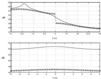
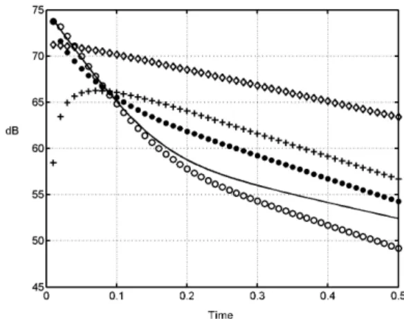
Such coupled room impulse responses can be synthesized using a recently proposed sound energy decay model based on a diffusion equation and adapted to coupled spaces.. This

The use of real data of the studied operating room (geometry, volume, extracted and blown air flow, temperature and hygrometry) will allow the determination of

We study the asymptotic behavior of random simply generated noncrossing planar trees in the space of compact subsets of the unit disk, equipped with the Hausdorff distance..

Using the harm value, defined by equation 7 for each road user, an action could be chosen in a dilemma situation. Since most ethical theories are created for personal forms of