HAL Id: hal-01282203
https://hal.archives-ouvertes.fr/hal-01282203
Submitted on 3 Mar 2016
HAL is a multi-disciplinary open access
archive for the deposit and dissemination of
sci-entific research documents, whether they are
pub-lished or not. The documents may come from
teaching and research institutions in France or
abroad, or from public or private research centers.
L’archive ouverte pluridisciplinaire HAL, est
destinée au dépôt et à la diffusion de documents
scientifiques de niveau recherche, publiés ou non,
émanant des établissements d’enseignement et de
recherche français ou étrangers, des laboratoires
publics ou privés.
Safety Trigger Conditions for Critical Autonomous
Systems
Amina Mekki-Mokhtar, Jean-Paul Blanquart, Jérémie Guiochet, David
Powell, Matthieu Roy
To cite this version:
Amina Mekki-Mokhtar, Jean-Paul Blanquart, Jérémie Guiochet, David Powell, Matthieu Roy.
Safety Trigger Conditions for Critical Autonomous Systems. The 18th IEEE Pacific Rim
Inter-national Symposium on Dependable Computing (PRDC 2012), Nov 2012, Niigata, Japan. 10p.,
�10.1109/PRDC.2012.22�. �hal-01282203�
Safety Trigger Conditions for Critical Autonomous Systems
Amina MEKKI-MOKHTAR∗†, Jean-Paul BLANQUART‡, J´er´emie GUIOCHET∗†, David POWELL∗† and Matthieu ROY∗†
∗ CNRS, LAAS, 7 Avenue du colonel Roche, F-31400 Toulouse, France
† Univ de Toulouse, LAAS, F-31400 Toulouse, France
{amekkim|guiochet|dpowell|roy}@laas.fr
‡ EADS Astrium, 31 rue des cosmonautes, 31402 Toulouse, France
jean-paul.blanquart@astrium.eads.net
Abstract—A systematic process for eliciting safety trigger conditions is presented. Starting from a risk analysis of the monitored system, critical transitions to catastrophic system states are identified and handled in order to specify safety margins on them. The conditions for existence of such safety margins are given and an alternative solution is proposed if no safety margin can be defined. The proposed process is illustrated on a robotic rollator.
Keywords-Safety, Dependability, Autonomous Critical Sys-tems, Safety Rules, Safety Constraints, On-line Monitoring, Safety Monitoring.
I. INTRODUCTION
Autonomous systems have to cope with various execution environments while guaranteeing safety, and in particular when they interact with humans, as is the case for robotic systems. These systems are often critical since their failure can lead to human injury or even death, or large financial losses. However, such systems are difficult to validate due to their high complexity and the fact that they operate within complex, variable and uncertain environments in which it is difficult to predict all possible system behaviors. Therefore, there has been considerable interest in making such systems safe [1], [2].
Safety can be defined in absolute terms as “the absence of catastrophic consequences on the user(s) and the envi-ronment” [3]. However, the notion of “zero risk” is utopian since systems can and do fail during execution. The IEC 61508 standard recognizes this and defines safety as “the absence of unacceptable risk” [4].
To obtain systems that fulfill their mission or avoid catastrophic failures, despite the presence of faults, a com-bination of several methods can be used [3], which are: fault prevention, fault tolerance, fault removal and fault forecasting. In the context of safety, a popular form of fault tolerance is safety monitoring through which the functional system is continuously monitored and forced to a safe state should some anomalous behavior be detected. Safety monitors appear in the literature under many different terms, such as: safety manager [5], autonomous safety system [6],
checker [7], guardian agent [8], safety bag [9], or diverse
monitor[4]. The latter IEC 61508 standard [4], distinguishes
two monitoring approaches: “(1) the monitor and the mon-itored function in the same computer, with some guarantee of independence between them; and (2) the monitor and the
monitored function in separate computers.”In the latter case,
the monitor is called a diverse monitor1, whose aim is to
“protect against residual specification and implementation faults in software which adversely affect safety”. For this very reason, we are particularly interested in the latter type of external safety monitor.
Thus, a safety monitor observes the behavior of the functional system and aims to ensure that it respects a set of safety constraints. It must be able to identify system states in which it can trigger remedial actions to prevent the occurrence of hazardous situations, i.e., situations in which people, property or the environment are exposed to one or more hazards [10].
In this paper, we introduce the concept of warning states, in which associated remedial actions, or safety actions, can be taken. The set of warning states represents the safety margin between nominal safe states and catastrophic states, i.e., those corresponding to hazardous situations.
The method for defining such warning states is not a trivial task. The method must be able to propose an alternative solution if a safety margin cannot be defined to handle a given safety constraint. However, to the best of our knowledge, there has been little research on this issue.
In this paper, we present a systematic process to elicit the set of warning states. The process can be summarized as follows: first, we extract sufficient conditions to avoid hazardous situations (we refer to these as safety conditions) using environmental quantities (we refer to these as safety-relevant variables) from a list a major risks resulting from a HAZOP/UML risk analysis. Second, for each safety con-dition, we propose a methodology to refine it and define, if possible, a safety margin on each safety-relevant variable, and thereby, the set of warning states. If a safety margin
can-1In the 1st edition of IEC61508 (1998), such a monitor was called a
“safety bag”, a term coined by early work on diverse monitors in the context of railway control [9].
not be defined for a particular variable, the safety condition must be enforced by some other mechanism (e.g., a physical interlock). Finally, if safety margins and safety actions have been defined, we verify the consistency of safety actions that can be carried out simultaneously.
The remainder of the paper is organized as follows: Sec-tion II discusses previous work related to runtime verifica-tion and safety monitoring. Secverifica-tion III presents terms used in our approach and gives some precise definitions. Section IV gives a brief overview of HAZOP/UML risk analysis, details the safety margin elicitation step and presents some initial results on safety action consistency checking. In Section V, we apply this process to a robotic rollator and finally, Section VI presents conclusions and future work.
II. RELATED WORK
Two of the important aspects of autonomous systems are: their ability to make decisions, and the uncertain en-vironment in which they operate, portending unexpected behaviors that, if nothing is done, could cause catastrophic damage. The need to make decisions autonomously in an uncertain environment gives rise to software that is often complex and error prone. Such software is difficult to verify exhaustively since the state space is potentially huge and cannot be defined in advance.
Runtime verificationappears as complementary method to
offline verification by theorem proving or model checking since some information about environment behavior may not be known before system deployment. Moreover, runtime verification is not concerned by the state explosion problem since only finite executions are checked. The IEEE defines runtime verification as: “the discipline of computer science that deals with the study, development, and application of those verification techniques that allow checking whether a run of a system under scrutiny satisfies or violates a
given correctness property” [11]. There have been several
interesting surveys and analyses of such approaches [12], [13], [14]. The authors highlight the appropriateness of runtime verification for safety-critical systems.
Checking whether an execution meets a correctness prop-erty is typically performed using a component called a monitor. The topic of our interest is safety monitors, which are monitors checking constraints that aim to guarantee the avoidance of catastrophic failures. Monitors have been widely discussed in the literature. As in the IEC 61508 definition presented in section I, the authors generally dis-tinguish two types of monitors:
• Non-independentmonitors, also called intrusive [15] or
in-line [13] monitors, such as those presented in [14],
[16], [17], [18]. These works aim to deal with real-time challenges like time sampling and the synchronization between the monitor and the monitored system. For example, in order to avoid code instrumentation (which would require re-certification) [14] considers Copilot, a
stream language for runtime verification by monitoring a set of global variables of the monitored system de-signed to achieve functionality (i.e., the monitor cannot change the monitored system’s behavior, unless the latter has violated its specification), certifiability, and timing isolation. Copilot-generated monitors can be in-tegrated with the observed program without modifying its functionality or real-time guarantees.
• Independent monitors, also called non-intrusive [15],
out-line[13] or diverse [4] monitors, have been widely
addressed. The application domains are various and include space [19], [6], robotics [7], healthcare [8], and railways [9]. These works address architectural issues like the safety monitor observation and reaction levels, the expression of the safety constraints in an adequate language, the verification of these constraints, and the definition of recovery actions.
As defined by the IEEE standard [11], monitoring requires some properties to be checked. In order to be checked by a monitor, the properties need to be expressed in an appropriate formalism. Early work has been done by Pnueli and Mana, who studied the language for specifying prop-erties of reactive systems [20]. They proposed an extension of ordinary predicate logic with a set of special temporal operators. Many variants of temporal logics have been developed in order to specify properties of real-time systems that can be checked by on-line monitoring. See for example, the comparative study by Alur and Henzinger [21], [22].
Despite numerous research works related to runtime ver-ification of systems in general and safety monitoring in particular, the problem of elicitation of the properties to be monitored has not been specifically addressed, to the best of our knowledge. Indeed, Leucker and Schallhart [12] cite the generation of monitors from high-level specifications as one of the key problems that needs to be addressed in runtime verification. In the previously cited works on safety monitoring [6], [7], [9], [19], [2], the properties to be checked were obtained from standards and/or from domain knowledge expertise, which can be problematic in terms of completeness. To address this issue, we propose in this paper a systematic process for eliciting the properties to be checked starting from a HAZOP/UML risk analysis. We refer to these properties as safety trigger conditions since, when such a condition is detected (i.e., the system has entered a warning state), the aim is to trigger appropriate safety actions to remedy the situation.
III. BASELINE AND CONCEPTS
A. Definitions
In the literature surveyed in Section II, various meanings are associated with terms such as: safety constraints, safety rules, safety requirements, safety properties, etc. In our previous work [23], we proposed some precise definitions
of these terms in order to base the proposed methodology on a firm conceptual foundation. We recall these definitions here together with some illustrative examples.
Safety Requirement. A safety requirement is general high-level specification of what it means for a system to be safe.
Example: “the robot must not cause the patient to fall”.
Safety condition. A safety condition is a sufficient condition to avoid a hazardous situation.
Example: “the robot is stationary and not used by a patient”.
Safety invariant (SI). A safety invariant is a necessary safety condition, i.e., the violation of a safety invariant is intolerable in that it implies an unacceptable risk of the violation of a high-level safety requirement.
Example: “the robot speed shall not exceed 3 m/s” (where 3 m/s is the speed beyond which harm is considered to be inevitable). Safety action. A safety action is an activity carried out explicitly to bring the system to a safe state.
Example : “apply emergency brake”.
Safety trigger condition (STC). A safety trigger condition is a condition that, when asserted, triggers a safety action.
Example: “the robot speed is greater than2 m/s”.
Safety margin. A safety margin is the “distance” between a safety trigger condition and the negation of a safety invariant.
Example: in the examples above, the safety margin between the safety trigger condition (the robot
speed is greater than2 m/s) and the negation
of the safety invariant (i.e., the robot speed is
greater than3 m/s) can be expressed in terms
of the difference of speed characterizing each
condition (i.e., here, 1 m/s).
Safety rule. A safety rule defines a way of behaving in response to a hazardous situation. A safety rule can be operationalized as an if-then rule:
Safety rule , if [safety trigger condition] then [safety
action].
Example: “if the robot speed is greater than2 m/s
then apply emergency brake.”
Figure 1 provides an illustration of the main concepts in terms of a partition of the possible states of the monitored system into safe, warning and catastrophic states. A safety trigger condition must be asserted when the system passes
from a safe state (e.g., xs on Figure 1) to a warning state
(e.g., xw). If the system is in a warning state, then the safety
monitor must trigger a safety action to bring the monitored system toward a safe state. The set of warning states specifies the safety margin. If the safety monitor fails to bring the system back into a safe state, it may reach a catastrophic
state (e.g., xc). The figure also illustrates the purpose of a
Figure labels (hide in final version)
SI(x) (1) SI(x) (2) ST C(x) (3) ST C(x) (4) SI(x)^ ST C(x) (5) SI(x)^ ST C(x) (6) (7) 3
Figure labels (hide in final version)
SI(x) (1) SI(x) (2) ST C(x) (3) ST C(x) (4) SI(x)^ ST C(x) (5) SI(x)^ ST C(x) (6) (7) 3
Figure labels (hide in final version)
SI(x) (1) SI(x) (2) ST C(x) (3) ST C(x) (4) SI(x)^ ST C(x) (5) SI(x)^ ST C(x) (6) (7) 3 Warning states Catastrophic states Safe states
Path to be aborted by safety action triggered by safety monitor
Path to be removed by a safety interlock (safety action) xs xc xw
Figure 1. Illustration of main concepts
safety interlock: the removal of paths that could lead the system from a safe state to a catastrophic state, without passing by an intermediate warning state.
Therefore, we can define a safety monitor versus a safety interlock as follows:
Safety monitor. A safety monitor is a mechanism that seeks to prevent undesired system states from being reached by
detecting unsafe system states and triggering appropriate
actionsto bring the system back to a safe state.
Safety interlock. A safety interlock is a mechanism that seeks to prevent undesired system states from being reached by inhibiting events that could cause such states to be reached from the current system state.
B. Safety invariants and safety trigger conditions
We formally define the previous terms in order to be able to determine the conditions under which an STC defines a valid safety margin.
Let x∈ X be the tuple of safety-relevant variables, x =
hx1, x2, ..., xni, such that X represents the set of discernible
system states.
A safety invariant is a predicate SI : X → B such that
SI is true in non-catastrophic states.
With respect to a safety invariant SI(x), the set of
catastrophic states,Xcata, of the monitored system is thus:
Xcata= {x ∈ X | SI(x)}
A safety monitor observes the tuple of safety-relevant variables and evaluates the system state by means of a safety
trigger conditionST C : X → B that evaluates to true when
the safety monitor judges that the system is not in a safe state. Thus, the set of safe states, as judged by the safety monitor, is defined by:
Obviously, we require that safe states not be catastrophic
states, i.e.,Xsafe ∩ Xcata= ∅, whence:
∀x ∈ X : SI(x) ∨ ST C(x) (1)
States that are neither safe nor catastrophic constitute a subset of system states in which the safety monitor can (and should) trigger a safety action aiming to prevent the monitored system from reaching a catastrophic state and bring it back to a safe state. We call this subset, the set of warning states. It is defined by:
Xwarn= {x ∈ X | SI(x) ∧ ST C(x)}
Considering now the possible transitions between system states, to implement a safety monitor we require every path from a safe state to a catastrophic state to pass through at least one warning state. To formalize this requirement, let
us consider a safe state xs and a catastrophic state xc, and
define a path from xs to xc as a functionπ:
π [0, 1] → X 0 7→ xs 1 7→ xc
such thatπ is a continuous function on continuous variables
and monotonous on discrete variables (π follows transitions
on discrete variables). We define Π(xs, xc) = {π| π is
a path from xs to xc} to be the set of all such paths.
The requirement that every path from a safe state to a catastrophic state passes though at least one warning state can thus be expressed as:
∀xs, xc, ST C(xs), SI(xc), (2)
∀π ∈ Π(xs, xc) : ∃ t, xw= π(t), ST C(xw) ∧ SI(xw)
Note that this constraint imposes that no state adjacent to a catastrophic state can be a safe state. If that were not the case, a safety interlock would be required to remove the corresponding transition.
With respect to a safety invariantSI(x), a safety trigger
condition must satisfy both constraints (1) and (2), which leads to the following definition:
Definition 1 (Safety Trigger Condition). A safety trigger
condition is a predicate ST C : X → B such that ST C is
false in safe states, true in catastrophic states, and transitions to true before reaching a catastrophic state on any path to the latter from a safe state. Formally:
∀xc, SI(xc) : ST C(xc)
∧ [∀xs, ST C(xs), ∀π ∈ Π(xs, xc) :
∃ t, xw= π(t), ST C(xw) ∧ SI(xw)]
IV. THE PROPOSED METHODOLOGY
In this section, we first briefly describe the starting point of our process – the definition of safety conditions based on the results of a risk analysis – and then detail how the requirements for safety monitors and safety interlocks can be derived from them.
A. Extraction of safety conditions
The starting point of our method is a HAZOP/UML risk analysis. This approach, presented in [24], is based on a description of the system using UML and an adaptation of the risk analysis technique HAZOP. HAZOP is a collabora-tive method, where each element of the system is analyzed considering possible deviations. Each deviation results from the application of a HAZOP guideword to an attribute of a UML model (this is noted in the “deviation” column of a HAZOP table, where each line corresponds to a deviation). Two further columns give the effect of the deviation in the context of the use case and in the real world.
We can extract three safety conditions from each line of a HAZOP table by negating the expressions obtained in the columns: Deviation, Use Case Effect, Real World Effect. Each safety condition is handled separately.
B. Safety margin and interlock elicitation process
If the safety condition is expressed using observable safety-relevant variables, we first consider that the safety condition is not only sufficient but necessary, i.e., it corre-sponds to a safety invariant.
A global safety invariantSI is expressed in its conjunctive
normal form, i.e.,SI = SI1∧. . .∧SIm, and each elementary
safety invariant SIi is expressed as a disjunction: SIi =
SIi(a)∨ SIi(b). . .. We refer the terms of the disjunction,
SIi(a), SIi(b), etc., as “atoms”. A similar suffix notation
is used for corresponding safety trigger conditions, e.g.,
ST Ci(a).
The disjunctive expression for SIi is then handled as
follows (we simplify the notation by usinga, b, etc. to denote
SIi(a),SIi(b), etc.):
1) Build the graph corresponding to the expression:
SIi = a ∨ b ∨ . . . such that nodes are defined by
minterms over the atomsa, b, . . . , and transitions are
labelled by the value of the atom that changes. For
instance, in Figure 2, the safety invariant is:SI≡ a∨b
which leads to 4 nodes and the associated transitions. For simplification, we limit the analysis to transitions inducing only one atom change, e.g., the transition
from the node ¯ab (which stands for ¯a ∧ b) to graph
node ¯a¯b that is labelled by ¯b. This step results in
a model which is similar to a “region automata” (used in temporal automata), i.e., each node defines a set of system states that satisfy a condition (for instance, region 1 is the set of system states that
of Section III-A, we can calculate the sets of
non-catastrophic regions and catastrophic regions.
2) We are concerned by the transitions between a
non-catastrophic region and a catastrophic region. We
call such a transition a critical transition (e.g., the
transitions with dotted circles around b and a in
Fig-ure 2), and the corresponding non-catastrophic region, a critical region; for example in Figure 2, regions (2) and (3) are critical regions. We analyze each critical transition separately to determine if a critical region can be split into a safe region and a warning region.
a b SI= a ! b ab ab ab ab ① ② ④ ③ a a b b
Figure 2. Region graph example
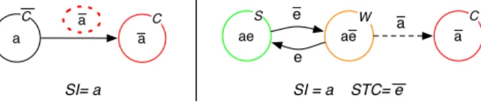
Based on Definition 1, a necessary condition for the existence of warning regions is the possibility to partition the non-catastrophic region into non-empty sub-regions. Con-sider the example of Figure 3 (C, S and W refer respectively to Catastrophic, Safe and Warning regions) corresponding
to the very simple case of SI = a. If a is defined by
a≡ (v < vmax), where v is a safety-relevant variable, then a
partition is possible and can be expressed as:{{x ∈ X | v ≤
vmax− β}, {x ∈ X | vmax− β < v < vmax}} (for some
β ∈]0, vmax[). Conversely, if a is defined by a ≡ (v = 0),
then a partition of {x ∈ X | (v = 0)} into two non-empty
sub-regions is not possible.
For similar cases, i.e., with atoms that are functions of one continuous variable, the previous necessary condition can be generalized as follows:
Condition 1 (Existence of a warning region). Let X be a
critical region defined by p∧ q (where p is an atom and q
is any conjunction of other atoms, including the trivial case q = true), with a critical transition labeled by p. A warning
region exists if and only if there exists a partition ofX, with
two partsX1= {x|p ∧ q ∧ e} and X2= {x|p ∧ q ∧ e} such
that e⇒ p.
Moreover, if such a partition exists, e, X1, and X2 are
possible candidates forST C, XsafeandXwarnrespectively.
Notice that, besides its simplicity, such a condition is valid for atoms which are function of continuous or dis-crete variables. For the previous example, the partition is
defined by e = (v < vmax− β), which actually implies
a = (v < vmax), as required.
For critical transition atoms that are functions of several variables, the condition is more complex, and is out of scope of this paper.
Figure 3 illustrates the partitioning in the simple case
where p∧ q = a. The critical region {x ∈ X|a} is
partitioned into two sub-regions: {x ∈ X|a ∧ e} ∈ Xsafe
and{x ∈ X | a ∧ ¯e} ∈ Xwarn. In this graph, in case of
violation ofe, the system enters the warning region, ae, and
thus triggers a safety action. The precise definition ofe, and
thus the safety margin, has to be carried out in collaboration with domain experts to guarantee that the safety action can
bring the system back into the safe region. The transitiona
to the catastrophic state labeled withC, is then considered
improbable (presented here with a dotted line).
If there exists a critical region with no possible partition, or if the proposed partition and its safety trigger condition are not validated by domain experts, two alternative solutions can be envisaged:
1) the definition of a safety interlock to prohibit the transition towards the catastrophic region,
2) the relaxation of the safety condition in order to allow a temporary violation; the inclusion of time as a supplementary safety-relevant variable must of course be accompanied by a re-assessment of the risks by safety and domain experts.
In this paper, we only consider the former solution (i.e., the introduction of a safety interlock if a safety margin cannot be defined).
In the following section, we propose a simple method for calculation of safety margins in the case of continuous variables. a a SI= a ae ae a a e e SI = a STC= e C S W C a C
Figure 3. The region graph before and after the safety margin elicitation
C. Special case of continuous variables
We consider here the case where safety invariants and safety trigger conditions are defined as a inequality relations on one or more continuous safety-relevant variables, that is:
SI(x) = (f (x) < 0) (3)
ST C(x) = (g(x)≥ 0) (4)
wheref, g : X → R.
In this rather common case, it is possible to reformulate the constraints (1) and (2), and Definition 1, in terms of functions over x.
Constraint (1) becomes:
∀x ∈ X : (f(x) < 0) ∨ (g(x) ≥ 0)
Noting that, given (3) and (4), we have SI(x) =
(f(x) ≥ 0) and ST C(x) = (g(x) < 0), we can rewrite constraint (2) as:
∀xs, xc, (g(xs) < 0), (f(xc) ≥ 0), ∀π ∈ Π(xs, xc) :
∃ t, xw= π(t), (g(xw) ≥ 0) ∧ (f(xw) < 0) (5)
Similarly, we can rewrite definition 1 as follows: Definition 2. When a safety invariant and a corresponding safety trigger condition are defined in terms of inequal-ities on functions of continuous safety-relevant variables:
SI(x) = (f (x) < 0) and ST C(x) = (g(x) ≥ 0), the
functiong(x) must satisfy:
∀xc, (f (xc) ≥ 0) : (g(xc) ≥ 0)
∧ [∀xs, (g(xs) < 0), ∀π ∈ Π(xs, xc) :
∃ t, xw= π(t),
(g(xw) ≥ 0) ∧ (f(xw) < 0)]
A particularly simple way to define a well-behaved safety trigger function is:
g(x) = f (x) + θ (6)
for some constantθ.
The safety margin defined must be sufficient to allow a recovery. This means that, depending on the physical constraints of the system (the maximum deceleration for instance), the safety margin must be defined such that the safety action has enough time to achieve its effect. Additionally, the safety margin should not be too restrictive, i.e., it must be defined such that the system can fulfill its mission. The safety margin definition is clearly a critical step since it requires a compromise to be reached between the system’s safety and availability. Therefore, the safety margin definition requires the collaboration of safety experts and domain experts.
D. Ensuring consistency of safety actions
It is important to check the consistency of the safety actions that can be carried out simultaneously. We give some preliminary ideas about how that can be facilitated using our approach.
To specify the safety actions within the resulting graph, we propose to model the system behavior using a Mealy machine, which is a particular type of finite state machine with outputs specified on transitions. This allows us to specify, for a particular transition that asserts a safety trigger condition, the corresponding safety action.
Remember that a global safety invariant SI is expressed as
a conjunction:SI = SI1∧· · ·∧SIm. When all the termsSIi
have been processed and the corresponding safety margins or safety interlocks specified, the corresponding graphs can be composed by taking their cartesian product. The resulting graph allows identification of transitions that trigger a safety action while another safety action is being carried out, and which are thus potential causes of inconsistency.
We give some preliminary results on safety action consis-tency checking in the case study below.
V. APPLICATION TO AMULTIMODALINTERACTIVE
ROBOT
In this section, the robotic rollator case study is used to validate the proposed methodology.
A. Target system
The MIRAS (Multimodal Interactive Robot for Assistance in Strolling) project aims to develop a semi-autonomous assistive robot for standing up and walking, designed to be used in elderly care centers by people suffering from gait and orientation problems (see Figure 4). The objective is to let these patients become more autonomous, by helping them to stand and sit, and walk around. The robot also includes functionality to monitor the physical and physiological state of the patient, and an ability to autonomously move to the patient’s position when summoned.
Figure 4. Prototype of MIRAS robotic assistant
B. Elicitation of safety margins
We consider the risk analysis of the use case management of strolling. From each line of the corresponding HAZOP deviation table, we can extract three safety conditions (see Figure 5), by negating the deviations obtained in the three concerned columns. Let us consider the first deviation: “the handles are not at the right height for strolling”.
The corresponding safety condition is: handles must be at the right height for strolling, where the “right height” is
The handles must be at the
right height for strolling The patient must not stroll in a bad position
The patient must not fall or have problems due to
posture
Deviation Use Case Effect Real World Effect
The handles are not at the
right height for strolling The patient strolls in a bad position problems due to postureThe patient falls or has
Safety conditions
Figure 5. Extraction of safety conditions from the HAZOP/UML table
defined by experts as an intervalI = [h min, h max]. Let
x= hh, vi be the vector of safety-relevant variables where
h∈ R+is the height of the handles of the robotic stroller and
v∈ R+ is the speed of the robot. Since these two variables
are indeed monitored in the considered system, we can formalize the previous safety condition as the required safety
invariant: SI(x) = ((v = 0)∨ (h ∈ I)), or equivalently,
SI(x) = a∨ b, where a = (v = 0) and b = (h ∈ I). Since
the safety invariant is expressed using a disjunction, the left part of Figure 6 illustrates the corresponding region graph. The two critical transitions are highlighted on the left part
of Figure 6: (v > 0) and (h /∈ I) on edges going to the
catastrophic region. v=0 h!I v>0 h!I v=0 h"I v>0 h"I C C C C v>0 v=0 h"I h!I v>0 h"I v=0 h!I v>0 h!I' v=0 h"I v>0 h"I v>0 h!I\I' S S S W C X v>0 h"I h!I h"I h"I' / Emergency stop h!I' v=0 v>0 # h"I' / Emergency stop v=0 v>0 # h!I' ① ② ④ ③ (A) (B) (D) (C) (E) Interlock
Figure 6. Processing of the safety condition: “handles must be at the “right height” for strolling”
1) Let us try to define a safety margin to insert a warning
region on the critical transition (v > 0) (left-part of
Figure 6 with a dotted circle). In this case, it is not possible to define a partition of the associated critical
region, defined by the atom (v = 0). Since (v = 0)
defines a single point, it is not possible to define an
atom e function of v, such that {x|(v = 0) ∧ e} and
{x|(v = 0) ∧ e} are different regions (Condition 1). Thus, no safety margin can be defined. Since the partition is not possible, an interlock needs to be
implemented to prohibit the critical transition(v > 0)
when v = 0 and h /∈ I. A simple one, with
agreement with domain experts, could be a physical blocking device engaged in the wheels that can only
be unblocked whenh∈ I.
2) Let us try to define a safety margin to insert a
warning region for the critical transition (h /∈ I).
In this case, it is possible to create a partition of
the region defined by (h ∈ I) and thereby define
a safety margin. An obvious solution is to define a
sub interval I0 included in I, leading to two parts
{x|h ∈ I0
} and {x|h ∈ I \ I0
}. But we show here that our approach is generic using the method presented in Section IV-C. The considered atom is:
SI(b)= (h ∈ I) = ((h > hmin) ∧ (h < hmax)).
Since h is a continuous variable, we can express the
safety invariant as an inequality:SI(b)(x) = (fb(x) <
0), where: fb(x) = max(hmin− h, h − hmax).
From (6), we can define gb(x) as follows: gb(x) =
fb(x)+hθ= max((hmin+hθ)−h, h−(hmax−hθ)),
which corresponds to a safety trigger condition
defined via (4) as: ST C(b)(x) = (h /∈ I0), where
I0= [h
min+ hθ, hmax− hθ].
The right part of Figure 6 illustrates the resulting graph. Region (2) of the left graph has been split on the right graph into two regions labelled (B) and (C). The transition leading to region (2) has been decomposed into two transitions: one leading to region (B) and the other to region (C). Similarly, the transition leaving region (2) has been decomposed into two corresponding transitions back to (A).
If the handle height h leaves the interval I0 while
the robot is strolling (transition from (B) to (C)), we trigger a safety action Emergency stop to stop the robot. This safety action consists of hard braking and thus impacts the velocity rather than the handle height. Indeed, we cannot act directly on the handle height since forcing the handles to put them at the correct height implies an additional means of actuation to override the (possibly faulty) nominal actuator. An
Emergency stopis also triggered should the robot start
to stroll while h is not in the interval I0 (transition
from (A) to (C)). V<Vmax-V! Vmax-V!"V<Vmax V#Vmax V# Vmax-V! / Braking V # Vmax v=0 h!I 0<v<Vmax-V! h!I' 0<v<Vmax-V! h!I\I' 0<v<Vmax-V! h"I v=0 h"I Vmax-V!"v<Vmax
h!I' Vmax-Vh!I\I'!"v<Vmax Vmax-Vh"I!"v"Vmax
v>Vmax
h!I' v>Vmaxh!I\I' V>Vmax
h"I v>0 V#Vmax V#Vmax h"I h!I' Vmax-V!"V / Emergency Stop V<Vmax-V! h"I h!I' h"I h!I v=0 h!I v>0 h!I' X Vmax-V!"v / Emergency Stop V<Vmax-V! V< Vmax-V!
v=0
h!I
v>0
h"I
v=0
h"I
v>0
h!I'
v>0 # h!I' v=0 v>0X h"Iv>0
h!I\I'
h!I' h"I' / brakes h"I' v>0 / brakes h"I h!I v=0 h"I' / brakes h"I' / brakes ① ② ③ h"I' v>0 / brakes v=0 Vmax-V!" v & h!I' / Emergency Stopv<Vmax-V! & h"I' / Brakes
S W C
Figure 8. Processing of the safety condition: the robot speed must always be less thanvmax
V<Vmax-V! Vmax-V!"V<Vmax V#Vmax V# Vmax-V! / Braking V # Vmax v=0 h!I 0<v<Vmax-V! h!I' 0<v<Vmax-V! h!I\I' 0<v<Vmax-V! h"I v=0 h"I Vmax-V!"v<Vmax h!I' Vmax-V!"v<Vmax h!I\I' Vmax-V!"v"Vmax h"I v>Vmax
h!I' v>Vmaxh!I\I' V>Vmaxh"I v>0 V#Vmax V#Vmax h"I h!I' Vmax-V!"V / Braking V<Vmax-V! h"I h!I' h"I h!I v=0 h!I v>0 h!I'
X
Vmax-V!"v / Braking V<Vmax-V! V< Vmax-V!v=0
h!I
v>0
h"I
v=0
h"I
v>0
h!I'
v>0 # h!I'v=0
v>0
X
h"I
v>0
h!I\I'
h!I'
h"I' /
brakes h"I' v>0 / brakesh"I
h!I
v=0 h"I' /Emergency Stop h"I' / Emergency Stop ① ② ③ h"I' v>0 / brakes v=0 S W C Interlock S S S W W W C C C C CFigure 7. The system region graph under the two safety invariants
C. Graph composition for consistency verification of safety actions
We now consider a second safety condition: the robot
speed must always be less thanvmax. We handle this safety
condition, as in the previous example, by introducing a
margin Vθ. The new warning state will trigger Braking if
the speed is near Vmax. Figure 8 illustrates the resulting
graph.
The overall safety invariant is SI(x) = ((v < vmax) ∧
((v = 0) ∨ (h ∈ I))), i.e., a conjunction of two elementary safety variants. Figure 7 illustrates the composition of the previous graphs, which highlights that:
• There is no transition that triggers two safety actions
simultaneously.
• The transition from warning region 1 to warning
re-gion 3 triggers a safety action Braking while another safety action Emergency Stop has already been trig-gered. This does not represent a case of inconsistency but it should be verified with the system expert whether simultaneous execution of both actions is possible and that it does not cause any damage should it occur. The same thing happens for the transition from warning region 2 to warning region 3: a safety action Emergency
Stop is triggered while another safety action Braking
has already been triggered.
VI. CONCLUSION AND FUTURE WORK
Safety monitoring for runtime verification of critical autonomous system is highly recommended. This on-line technique requires the definition of the safety properties to be checked. However, to the best of our knowledge, there has been no previous work on a systematic method for defining such properties. This paper proposes a solid methodology to elicit safety properties in the form of safety trigger conditions, based on the outputs of a risk assessment process.
The proposed methodology is systematic and enables us to handle each deviation separately and thus deal with system complexity. Once the deviations are handled, the resulting region graphs can be composed to describe the system behavior under the overall safety invariant and thereby allow the consistency of the safety actions to be checked.
We are currently envisaging an implementation within the context of the presented case study. For future work, we can identify several directions, particularly defining formal meth-ods for state graph specification and defining a systematic method for safety action consistency checking. We aim to apply the method to a larger number of examples available on our case study and finally, we plan to develop a prototype safety monitor implementing the generated safety rules and to experiment it on the rehabilitation robot.
ACKNOWLEDGEMENTS
This work was partially supported by the MIRAS Re-search Project, funded under the TecSan (Technologies for Healthcare) program of the French National Research Agency (French ANR) and SAPHARI, Project funded under the 7th Framework Programme of the European Community.
REFERENCES
[1] R. Alami, A. Albu-Schaeffer, A. Bicchi, R. Bischoff, R. Chatila, A. De Luca, A. De Santis, G. Giralt, J. Guiochet, G. Hirzinger, F. Ingrand, V. Lippiello, R. Mattone, D. Powell, S. Sen, B. Siciliano, G. Tonietti, and L. Villani. Safe and dependable physical human-robot interaction in anthropic domains: State of the art and challenges. In Workshop on Physical Human-Robot Interaction in Anthropic Domains, IEEE/RSJ International Conference on Intelligent Robots and Systems, page 15, Beijing, China, 2006. IEEE.
[2] Sami Haddadin, Alin Albu-Sch¨affer, and Gerd Hirzinger. Requirements for safe robots: Measurements, analysis and new insights. International Symposium on Robotics Research, 28(11-12):1507–1527, November 2009.
[3] A. Aviˇzienis, J. C. Laprie, B. Randell, and C. Landwehr. Basic concepts and taxonomy of dependable and secure computing. IEEE Transactions on Dependable and Secure Computing, 1:11–33, 2004.
[4] IEC 61508-7. Functional safety of electrical / electronic
/ programmable electronic safety-related systems - part 7: Overview of techniques and measures. International Organi-zation for StandardiOrgani-zation and International Electrotechnical Commission, 2010.
[5] C. Pace and D. Seward. A safety integrated architecture for an autonomous safety excavator. In International Symposium on Automation and Robotics in Construction, 2000. [6] S. Roderick, B. Roberts, E. Atkins, and D. Akin. The Ranger
robotic satellite servicer and its autonomous software-based safety system. IEEE Intelligent Systems, 19:12–19, 2004. [7] F. Ingrand and F. Py. Online execution control checking for
autonomous systems. In The 7th International Conference on Intelligent Autonomous Systems, Marina del Rey, California, USA, 2002.
[8] J. Fox. Designing Safety into Medical Decisions and Clinical Processes. In International Conference on Computer Safety, Reliability and Security, volume 1, 2001.
[9] P. Klein. The safety-bag expert system in the electronic
railway interlocking system Elektra. Expert Systems with
Applications, 3:499 – 506, 1991.
[10] ISO/IEC-Guide51. Safety aspects - Guidelines for their
inclusion in standards. International Organization for Stan-dardization and International Electrotechnical Commission, 1999.
[11] IEEE Std 1012-2004. IEEE standard for software verification and validation. Institute of Electrical and Electronics Engi-neers IEEE, Revision of IEEE Std 1012-1998, 2005. [12] Martin Leucker and Christian Schallhart. A brief account
of runtime verification. Journal of Logic and Algebraic
Programming, 78(5):293 – 303, 2009.
[13] Alwyn Goodloe and Lee Pike. Monitoring distributed
real-time systems: A survey and future directions . Technical
report, NASA Aviation Safety Program Office, 2010. [14] L. Pike, S. Niller, and N. Wegmann. Runtime verification
for ultra-critical systems. In 2nd International Conference on Runtime Verification, San Francisco, California, USA, 2011.
[15] B.A. Schroeder. On-line monitoring: a tutorial. IEEE
Computer Journal, 28(6):72 –78, jun 1995.
[16] Klaus Havelund. Runtime verification of C programs. In 20th IFIP TC 6/WG 6.1 international conference on Testing of Software and Communicating Systems: 8th International Workshop, TestCom ’08 / FATES ’08, pages 7–22, Berlin, Heidelberg, 2008. Springer-Verlag.
[17] Moonjoo Kim, M. Viswanathan, H. Ben-Abdallah, S. Kannan, I. Lee, and O. Sokolsky. Formally specified monitoring of temporal properties. In Real-Time Systems, 1999. Proceedings of the 11th Euromicro Conference on, pages 114 –122, 1999.
[18] Klaus Havelund and Grigore Roau. An overview of the
runtime verification tool java pathexplorer. Formal Methods in System Design, 24:189–215, 2004.
[19] J.P. Blanquart, S. Fleury, M. Hernerk, and C. Honvault. Software safety supervision on-board autonomous spacecraft. In 2nd European Congress Embedded Real Time Software, 2004.
[20] Z. Manna and A. Pnueli. Temporal Verification of Reactive Systems: Safety. Springer, New York, 1995.
[21] R. Alur and T.A. Henzinger. Real-time logics: complexity and expressiveness. In Logic in Computer Science, 1990. LICS ’90, The Fifth Symposium on Logic in Computer Science, pages 390 –401, jun 1990.
[22] R. Alur and T.A. Henzinger. A really temporal logic. J. ACM, 1994.
[23] Amina Mekki Mokhtar, J´er´emie Guiochet, David Powell, Jean-Paul Blanquart, and Matthieu Roy. Elicitation of ex-ecutable safety rules for critical autonomous systems. In Em-bedded Real Time Software and Systems (ERTS2), Toulouse, France, 2012.
[24] D. Martin-Guillerez, J. Guiochet, D. Powell, and C. Zanon. A UML-based method for risk analysis of human-robot
interactions. In 2nd International Workshop on Software