Publisher’s version / Version de l'éditeur:
Vous avez des questions? Nous pouvons vous aider. Pour communiquer directement avec un auteur, consultez la première page de la revue dans laquelle son article a été publié afin de trouver ses coordonnées. Si vous n’arrivez pas à les repérer, communiquez avec nous à [email protected].
Questions? Contact the NRC Publications Archive team at
[email protected]. If you wish to email the authors directly, please see the first page of the publication for their contact information.
https://publications-cnrc.canada.ca/fra/droits
L’accès à ce site Web et l’utilisation de son contenu sont assujettis aux conditions présentées dans le site
LISEZ CES CONDITIONS ATTENTIVEMENT AVANT D’UTILISER CE SITE WEB.
Canadian Building Digest, 1968-01
READ THESE TERMS AND CONDITIONS CAREFULLY BEFORE USING THIS WEBSITE. https://nrc-publications.canada.ca/eng/copyright
NRC Publications Archive Record / Notice des Archives des publications du CNRC :
https://nrc-publications.canada.ca/eng/view/object/?id=35788dfc-6cf9-48b8-ac89-80ae55b47219
https://publications-cnrc.canada.ca/fra/voir/objet/?id=35788dfc-6cf9-48b8-ac89-80ae55b47219
NRC Publications Archive
Archives des publications du CNRC
For the publisher’s version, please access the DOI link below./ Pour consulter la version de l’éditeur, utilisez le lien DOI ci-dessous.
https://doi.org/10.4224/40000828
Access and use of this website and the material on it are subject to the Terms and Conditions set forth at
Look at joint performance
Canadian Building Digest
Division of Building Research, National Research Council Canada
CBD 97
Look at Joint Performance
Originally published January 1968.G.K. Garden
Please note
This publication is a part of a discontinued series and is archived here as an historical reference. Readers should consult design and regulatory experts for guidance on the applicability of the information to current construction practice.
Joint designs have traditionally been developed through trial and observation on actual buildings, a process that tends to be slow and too expensive when performance is not adequate. Present rapid changes in materials and methods of construction demand that new joint designs be developed and proved quickly. Although performance tests have been of some value in accelerating this process, they have seldom provided adequate proof of final
performance. To meet changing needs, scientifically sound principles, which have been fairly well established in previous Digests, must be followed in designing joints.
In-service performance is always the final proof of any design. Thus, examinations designed to determine why some joints succeed and others fail can be very useful in advancing design capability. The value of such studies, however, is directly related to the ability of the
investigator to appreciate the factors that make for success or failure. This Digest will discuss joints in service on actual buildings in order to draw attention to the main factors influencing their performance and to indicate the value of field investigation.
Traditional Joints
Shingled walls are normally accepted as walls that do not leak. Ignored or forgotten because of their unquestionable success are the myriad of joints present. Analysis shows that in these joints the four forces that can act to drive water inward are adequately controlled (CBD 40). Shingles are overlapped in such a manner that raindrops cannot enter the wall by their own kinetic energy and gravity draws them down the exterior surface. The rather large vertical joints between shingles allow pressure equalization of the space between them and the air barrier, preventing the development of the inward air pressure drop that is instrumental in most cases of rain penetration. Although some capillary passages exist, the net force acting on the water in them is outward.
Joints in solid walls of unit masonry, where the elimination of all leakage openings is
attempted, have been generally unsatisfactory in preventing rain penetration. This is clearly shown by the many attempts to improve their performance through the use of overhanging eaves, cornices, belt courses, stucco and even weatherboard siding. When the face wythe of a masonry wall has been separated from the rest of the wall by a drained cavity, a better
performance has been normal. Because all forces acting to drive water inward through the face wythe of a traditional cavity wall are not adequately controlled, however, some water does pass
through it. To prevent wetting of the inner wythe, bridges across the cavity must be avoided, the cavity must be adequately drained, and the base must usually be flashed.
Recently Designed Joints
Study No. 1. On the Atlantic coast where rain is frequently accompanied by high winds, a large
building suffered severe but localized rain penetration of the cavity masonry walls. Examination showed that water that penetrated the face wythe could not drain through the small weep holes because of an inward air flow. The flashing at the base of the wall bad been omitted and the water drained to the interior. After some discussion, the owners were encouraged to open vertical joints in the bottom course of the face brick, to caulk the joint between the inner wythe and the bearing surface (at the inside), and to replace bricks in the face wythe at frequent intervals with brick-sized louvres. In the three years since this work was done, despite many driving rain storms, no rain penetration has been reported. With the larger weep holes and caulking, the water can drain outward more easily than inward; and louvres provide greater freedom for air to enter the cavity, thereby reducing the inward air pressure drop at the wetted plane. The amount of water that actually passes through the outer wythe has been reduced, and drainage to the exterior is not hindered by an inward air flow.
Study No. 2. Both shingled and cavity walls are construction systems in which joints are not
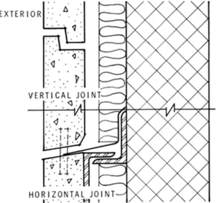
continuous from outside to inside. This feature can be used to advantage in designing with contemporary materials and methods of construction, an approach that was employed in the design of the walls of a large concert hall. The masonry back-up walls were insulated on their outer surface and large precast concrete facing elements were used as the exterior finish. As they were aware of the rain screen or two-stage weatherstripped principle (CBD 40), the designers specified that all joints in the precast concrete cladding should be left open. The horizontal joints were sloped toward the exterior and the vertical joints were half-lapped, but a 1/2-in. wide clear space was maintained between all panels (Figure 1). In the four years this building has been in service there has been no indication of rain penetration, nor even of partial penetration of the open joints.
Figure 1. Joints between concrete cladding panels.
It should be mentioned that the cavity was not left continuous around the building or
could normally develop from wind pressure variations over the building surfaces the cavity was blocked vertically at approximately 4-ft centres for 20 ft from each corner and horizontally at panel supports.
Study No. 3. Through-wall joints are employed in many contemporary buildings, and a number
of studies of individual cases have been made. A particularly interesting and informative experience was gained during construction of a tall building in Eastern Canada. During
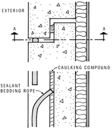
installation of the precast concrete wall panels, a bead of caulking compound was placed in the half-lapped joints (Figure 2). The fact that it did not provide an airtight seal was not considered important because a bead of elastomeric sealant was to be installed at the outside face of the joint. The installation of this sealant, however, had to be delayed because of cold weather, and only the sealant bedding rope was placed in the joint. Because the delay was expected to be more than six months the sealant bedding rope was installed with the upper end of each length turned inward to flash the joint space, incidentally leaving a 2- to 3-in. gap at frequent
intervals. No rain penetration was noticed during the delay. Only after installation of the elastomeric sealant at the outside of the joint was leakage observed, and after a few months it became a serious problem.
SECTION A-A
Figure 2. Vertical joint between concrete wall panels. Note: Although rain penetration can be controlled in the joints, the use of this wall design is not recommended (CBDs 98and94)
Study of the situation that existed during the delay indicated that although the caulking had not provided a complete air seal, it was considerably more airtight than that provided by the
sealant bedding rope. The air pressure on both sides of the sealant bedding rope could equalize and the air pressure difference required to move water past it could not develop (CBD 96). When the elastomeric sealant was finally installed, however, it was far more airtight than the caulking bead, with the result that the air pressure difference between inside and outside the building was borne by it. With both air and water leakage resisted at the same point, rain penetration occurred at even minor failures of the seal. As the outer seal was better than the
inner seal, any water that entered the joint could only drain to the building interior. The same conditions and performance were experienced at the window joints.
Study No. 4. A humidified building had severe condensation on the window frames and
adjacent wall areas. The exterior walls were constructed of precast concrete panels, with insulation and a light finish applied to the interior. While examining this problem in January, a little more than a year after the building had been completed, the building superintendent complained that the wall joints were leaking again. The joints between the concrete panels had been resealed at the outside during the previous summer because of rain penetration. The complaint appeared ridiculous, however, because there had been no rain for several months. Examination showed that condensate had accumulated as frost in the joints and because of a temperature rise was melting and draining to the interior.
Several factors contributed to the development of this problem. The basic wall design was rather poor with respect to thermal and moisture considerations (CBD 48, CBD 50,CBD 93). In accordance with common practice, the interior finish had been omitted behind the air conditioning induction units and above the suspended ceiling. This allowed the humid air in the building to move by convection through the cold joint space where it contacted cold outer materials (CBD 23,CBD 72). If the seal in the joint had been located at the interior, the severity of this problem could have been reduced.
Study No. 5. When icicles larger than a man's arm were falling from a point several hundred
feet above the ground, a very busy street had to be cordoned off. Examination revealed that the wall design followed the common practice of sealing a curtain wall against rain penetration at the exterior surface. This seal had been considered capable of preventing air leakage and therefore no attempt had been made to provide a seal at the interior. It had been realized, however, that rain penetration frequently occurred in curtain walls sealed at the exterior and an intricate drainage system had been incorporated within the wall, with openings to permit water to flow back to the exterior.
During cold weather the convective interchange of moist air from inside the building with cold spaces in the wall, plus the outward air flow through drainage holes (especially at upper floors), resulted in excessive condensation within the wall. An incidental but troublesome problem was the dirt streaking of window glass from the almost constant dripping of water from the drain holes. During extremely cold weather, particularly in the north wall, condensation occurred and accumulated as frost. Following a rise of exterior temperature to about 25°F, the frost within the wall melted and drained to the exterior. Here it froze, producing the large icicles and associated hazards.
Study No. 6. Examination of a metal and glass curtain wall disclosed a complicated combination
of problems that clearly demonstrate the close interdependence of one problem with another. The mullions of the curtain wall grid were attached to the building at each floor, with expansion joints directly above the connections and coinciding with the middle of the spandrels. The transom bars were attached to the mullions and the sealed double glazing units for both windows and spandrels were held in the aluminum grid by structural neoprene gaskets. The seal against rain and air leakage, however, was dependent upon the ability of the glass to hold the gasket tightly against the aluminum mullions and transom bars.
The effects of temperature variations, although allowed for in the mullions, were not
adequately considered in the design of the joints between the various wall elements, nor even in the design of the gasket cross-section. A drop in temperature was reflected in thermal contraction of the various wall components (CBD 56), and resulted in loss of the pressure required to maintain the gasket seals. Because the joint design was dependent upon a perfect seal, which was now lost, both rain penetration and air leakage occurred (CBD 55). The design and performance of the metal parts of the wall were similar to those previously described and contributed further to the wall problems. With rather high air leakage rates, severe
condensation produced large icicles, so that winter use of the building humidification system had to be discontinued (CBD 42).
Expansion accompanying a rise in temperature caused the vertical dimension at the spandrel to reduce. This, combined with the lack of clearance resulted in edge loading of the glass. The temperature rise at the spandrel was extreme because a black-faced thermal insulation was located inward of the space behind the sealed glazing unit. It was calculated that under bright sunshine the temperature at the black surface would approach 250°F and that the air in the sealed glazing unit could reach 180°F. This combination of air expansion in the sealed glazing unit and edge loading due to differential movements resulted in breakage of many panes of glass, despite the use of safety toughened glass.
Conclusion
Trial in service is the final proof of a joint design. Field observations, in addition to disclosing causes of failure, can provide proof of the validity of new design principles and give designers greater confidence and capability in applying them to new work. It should be stressed that the design principles used in the preceding analyses were unrecognized when most of the joints were designed. Hindsight is always easier than foresight, but it should be used to the greatest advantage.