RESEARCH OUTPUTS / RÉSULTATS DE RECHERCHE
Author(s) - Auteur(s) :
Publication date - Date de publication :
Permanent link - Permalien :
Rights / License - Licence de droit d’auteur :
Bibliothèque Universitaire Moretus Plantin
Institutional Repository - Research Portal
Dépôt Institutionnel - Portail de la Recherche
researchportal.unamur.be
University of Namur
Structural and quantitative analysis of nitrided stainless steel coatings deposited by
dc-magnetron sputtering.
Terwagne, Guy; Colaux, Julie; Collins, George; Bodart, Franz
Published in:Thin Solid Films
Publication date:
2000
Document Version
Publisher's PDF, also known as Version of record
Link to publication
Citation for pulished version (HARVARD):
Terwagne, G, Colaux, J, Collins, G & Bodart, F 2000, 'Structural and quantitative analysis of nitrided stainless steel coatings deposited by dc-magnetron sputtering.', Thin Solid Films, vol. 377-378, pp. 441-446.
General rights
Copyright and moral rights for the publications made accessible in the public portal are retained by the authors and/or other copyright owners and it is a condition of accessing publications that users recognise and abide by the legal requirements associated with these rights. • Users may download and print one copy of any publication from the public portal for the purpose of private study or research. • You may not further distribute the material or use it for any profit-making activity or commercial gain
• You may freely distribute the URL identifying the publication in the public portal ?
Take down policy
If you believe that this document breaches copyright please contact us providing details, and we will remove access to the work immediately and investigate your claim.
Structural and quantitative analysis of nitrided stainless steel
coatings deposited by dc-magnetron sputtering
G. Terwagne
a,U, J. Colaux
a, G.A. Collins
b, F. Bodart
aa
Laboratoire d’Analyses par Reactions Nucleaires, Facultes Uni´ ´ ´ ¨ersitaires Notre-Dame de la Paix, 61, rue de Buxelles-B-5000, Namur, Belgium
b
Australian Nuclear Science and Technology Organisation, Lucas Heights PMB 1, Menai, Australia
Abstract
Stainless steel coatings were deposited at a low temperature on low-carbon steel and mono-crystalline silicon substrates by dc-magnetron sputtering in a reactive atmosphere of nitrogen at room temperature. The total mass flow of argon and nitrogen
Ž .
was kept constant 20 sccm for all depositions and the nitrogen mass flow varied between 0 and 10 sccm with increments of 1 sccm, while the argon mass flow was decreased by the same amount. The elemental composition of the coatings and their
Ž .
deposition rate were studied by Rutherford backscattering spectroscopy RBS , by X-ray emission induced by charge particles ŽPIXE , and by nuclear reaction analysis NRA . The nitrogen content was found to increase with increasing mass flow up to a. Ž .
Ž .
saturation value of 40 at.%. A structural analysis by means of conversion electron Mossbauer spectroscopy CEMS and grazing¨
Ž .
incidence X-ray diffraction GXRD was also performed. The results indicated the presence of the so-called S-phase, probably due to nitrogen in solid solution at interstitial sites in the austenite lattice. The lattice expanded as the nitrogen mass flow increased. This phase is particularly interesting for industrial applications because it increased the resistance to wear without compromising the corrosion resistance of the steel.䊚 2000 Elsevier Science B.V. All rights reserved.
Keywords: PVD; Magnetron sputtering; Stainless steel; Nitrogen
1. Introduction
Austenitic stainless steels are well known for their corrosion resistant qualities but their performance is limited by their poor wear resistance. Nitriding of these steels can be performed by several techniques, such as
w x
conventional ion implantation 1᎐6 , pulsed plasma
ni-w x Ž 3.
triding 7 and plasma immersion ion implantation PI w x8 . As long as the treatment temperature is kept below a critical value of approximately 450⬚C, the wear resis-tance can be improved without compromising the cor-rosion performance. At these lower temperatures,
ni-UCorresponding author. Tel.: 54-78; fax:
q32-81-72-54-74.
Ž .
E-mail address: [email protected] G. Terwagne .
trogen remains in solid solution, producing a phase w x that has been variously called the ‘S-phase’ 9 ,
‘ex-w x w x
panded austenite’ 10,11 or ␥ phase 4᎐6 .N
Magnetron sputtering offers new possibilities and more flexibility for producing coatings on various sub-strates at low temperatures. While coatings sputtered from austenitic stainless steel targets at a low
tempera-w x ture usually form a ferritic bcc structure 12 , the addition of nitrogen to the sputtering gas results in a nitrogen-supersaturated fcc phase with improved wear
w x
resistance and higher corrosion resistance 13᎐15 . These coatings, whose properties and structure are similar to the ‘S-phase’ produced by nitriding, can be produced by dc-magnetron sputtering using stainless steel targets ᎏ a more convenient option than using expensive chromium targets to produce CrN coatings.
The purpose of this paper was to present a detailed
0040-6090r00r$ - see front matter 䊚 2000 Elsevier Science B.V. All rights reserved. Ž .
( ) G. Terwagne et al.rThin Solid Films 377᎐378 2000 441᎐446 442
Ž .
analysis elemental and structural composition of
coat-Ž .
ings sputtered from a stainless steel AISI 303 target in nitrogenrargon gas mixtures. Elemental composi-tion analysis was realized by nuclear reaccomposi-tions analysis ŽNRA , X-ray emission induced by charge particles. ŽPIXE. and Rutherford backscattering spectroscopy ŽRBS , whereas structural analysis was performed by. means of conversion electron Mossbauer spectroscopy
¨
ŽCEMS and grazing X-ray diffraction GXRD .. Ž .
2. Sample preparation
The coatings were deposited using an unbalanced dc-magnetron sputtering system placed in a small chamber of 0.05 m3 equipped with a 280-lrs turbo-molecular pump which provided a base pressure of
y5 Ž
10 Pa. A 50-mm diameter AISI-303 composition in wt.% ᎏ Fe: 70%, Cr: 18%, Ni: 9%, Mn: 2%, and
.
Si:1% disk target was placed just above the magnets with a good thermal contact to the holder in order to cool the magnetic material with water during deposi-tion. The source to sample holder distance was 150 mm and a chimney was placed on the top of the target to prevent contamination of the whole chamber. A shut-ter was placed between the top of the chimney and the sample holder in order to avoid deposition during target cleaning for 5 min before each deposition.
Two sets of substrates were used in this study:
Ž .
1. Si 100 wafers to measure the deposition rates and the elemental analysis of the coatings; and
2. low-carbon steel for the elemental and structural analysis.
Substrates were cut into 20=20 mm square coupons and cleaned in an ultrasonic bath with pentane before loading into the chamber. Prior to each deposition, the
Ž .
substrates which were grounded were etched for 2 min in order to remove oxide from the steel surface and to enhance coating adhesion.
Depositions were made at room temperature in the same conditions for both sets of substrates. The mag-netron power was set to 100 W during deposition and the voltage applied to the sputter target was approxi-matelyy400 V. Although the substrate was heated by electron and ion bombardment, the temperature was measured below 100⬚C during deposition with a ther-mocouple placed at the rear of the specimen. The coatings were reactively deposited for 20 min with various ArrN gas mixtures, which gave a thickness of2 approximately 400 nm. The proportion of N2 in the sputter gas was varied by changing the N flow rate2 with a compensating adjustment of the Ar flow rate, such that the total gas flow rate remained constant at 20 sccm. These flows correspond to a total pressure of
0.27 Pa measured with a baratron gauge placed in the deposition chamber.
3. Coating characterization
3.1. Elemental analysis
Nuclear elemental analyses were performed at LARN
¨
with ALTAIS, the new 2-MV Tandetron accelerator. The thickness and composition of the coatings were measured by Rutherford backscattering spectroscopy ŽRBS. and particle-induced X-ray emission ŽPIXE. techniques with 2 MeV incident ␣ particles. These measurements were made on the coatings on silicon substrates to avoid interfering signals from the sub-strate. The scattered particles were detected in a
passi-Ž .
vated implanted planar silicon detector PIPS at 175⬚ relative to the incident beam. By fitting the experimen-tal spectrum, it was possible to obtain the thickness of the coating. The deposition rates were then calculated
Ž .
and are presented in Fig. 1. The Si Li detector placed at 135⬚ relative to incident beam recorded X-rays emit-ted from the sample during RBS measurements. The relative amounts of Cr, Fe, Ni and Mn measured by the PIXE technique are reported in Table 1.
Ž .
Nuclear reaction analysis NRA was used to
mea-14
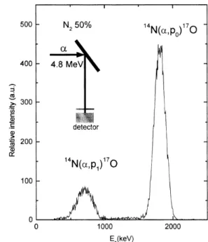
Ž .17 sure the nitrogen concentration using N ␣, p O at 4.8 MeV. A typical particle spectrum is shown in Fig. 2.
Ž .
Although endoenergetic Qsy1.191 MeV , this nu-clear reaction was suitable for nitrogen analysis
be-Ž .
cause it showed a constant cross section 5 mbrsr at 90⬚ for incident energies ranging between 4.6 and 4.8
w x
MeV 16 . A 24.4-m mylar absorber was placed in front of the particle detector to avoid elastic scattered particles in the PIPS detector. The nitrogen concentra-tions are also reported in Table 1.
Table 1
Relative amount of Fe, Cr, Ni and Mn measured for different coatings. Argon and nitrogen flow percentages are relative to the total flux in the deposition chamber
w x w x w x w x w x Ar flow N flow2 Fe Cr Ni Mn N Ž%. Ž%. Žat.%. Žat.%. Žat.%. Žat.%. Žat.%.
100 0 70.4 19.2 8.5 2.0 0.0 95 5 62.0 16.8 7.5 1.8 11.9 90 10 55.2 15.0 6.7 1.6 17.0 85 15 51.5 13.9 6.3 1.5 26.8 80 20 48.0 13.0 5.8 1.4 31.7 75 25 45.3 12.3 5.5 1.3 35.6 70 30 43.3 11.7 5.3 1.3 38.4 65 35 43.3 11.7 5.3 1.3 38.4 60 40 40.8 11.0 5.0 1.2 42.0 55 45 37.8 10.2 4.6 1.1 46.2 50 50 37.6 10.2 4.6 1.1 46.5
Fig. 1. Deposition rates measured by RBS technique on the coatings on silicon substrates as a function of nitrogen flow.
3.2. Structural analysis
Conversion electron Mossbauer
¨
spectroscopy ŽCEMS was used to determine the different phases. formed after deposition of the nitrogen-rich stainless steel coatings on the low carbon steel substrates. As is well known, CEMS is most sensitive to the top 0.1m Žnearly 80% of conversion electrons come from this.
depth , even though there is some contribution to the signal from depths up to ;0.3 m, but with decreasing
w x
efficiency 17 . The Mossbauer measurements were
¨
made at room temperature using a 57Co source in arhodium matrix with an initial activity of 50 mCi. The specimen of interest was placed in gas flow proportio-nal counter where the 7.3-keV conversion electrons resulting from recoilless resonant absorption by 57Fe
Fig. 2. Experimental NRA spectrum measured with 4.8 MeV ␣-par-ticles detected at 90⬚ for a typical stainless steel coating deposited by unbalanced dc-magnetron sputtering on a low carbon steel substrate.
nuclei within the specimen were detected. The velocity of the Mossbauer spectrometer was calibrated by
¨
recording a reference spectrum of an ␣-Fe phase pre-sent in metallic iron. The Mossbauer spectra recorded
¨
on each sample are presented in Fig. 3. On eachŽ .
Mossbauer spectrum Fig. 3b
¨
᎐l we can observe thesextet due to ␣-Fe present in the low carbon steel Žsame sextet as in Fig. 3a . A few ferromagnetic compo-.
Ž . Ž . Ž .
Fig. 3. Mossbauer spectra obtained by CEMS technique on: a metallic¨ ␣-Fe iron; and b ᎐ l stainless steel coating deposited by dc-magnetron
sputtering on a low carbon steel substrate in different flows reactive gas mixing atmosphere of argon and nitrogen. The relative amount of nitrogen is indicated on the left upper corner of each figure.
( ) G. Terwagne et al.rThin Solid Films 377᎐378 2000 441᎐446 444
Ž .
nents were also observed for low N flows2 -25% and a paramagnetic doublet was observed for higher N2
flows.
Grazing incidence XRD patterns were obtained from the coatings on the low carbon steel substrates with a Siemens D500 diffractometer using CoK␣ radiation
˚
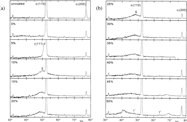
Žs1.789 A with a post-specimen monochromator. acting in the parallel mode. The scans were performed at an incidence angle ␣s1⬚ over Bragg angles from 2s30⬚ to 2s80⬚, counting for 30 s at 0.05⬚ inter-vals. The grazing incidence XRD patterns had a sub-stantial background, particularly at lower Bragg angles. There was also a component from the sample holder. With the broad peaks produced in the sputtered coat-ings, it was difficult to use standard background sub-traction routines. As an alternative, the background was calculated from an uncoated sample and sub-tracted from the scans obtained from the coated sam-ples. The results are shown in Fig. 4a,b.
The small unidentified peaks in the GXRD patterns at 2s31.8⬚, 41.8⬚, 48.1⬚ and 63.8⬚ were present in the diffraction pattern obtained from an empty sample holder, although the last three also corresponded to peaks from Fe O . No additional peaks were visible2 3 from the coating deposited in pure argon. The 5% N2 flow coating had a peak at 2s51.3⬚ which was close
Ž . Ž .
to the position of the 111 ␥-austenite peak 51.05⬚ . At higher a nitrogen content in the gas flow, this peak
w x
was replaced by a broad peak, labeled S 14 in Fig. 4, which moved to lower Bragg angles and broadened as the nitrogen content in the gas flow was increased. At 50% N flow, the peak eventually disappeared although2
a new peak at 2s41⬚ appeared. Another broad peak appeared at 2s68⬚ in the sample deposited with 45% N2 flow which moved up to 2s69⬚ in the sample made with 50% N flow.2
4. Results and discussion
Fig. 5 shows the evolution of nitrogen concentration in the coatings corresponding to different nitrogen flows. The results obtained by NRA and RBS tech-niques showed a remarkable agreement. The total amount of nitrogen was found to be proportional to the nitrogen flow until this reached 25% of the total flow. At higher flow, a maximum nitrogen content of approx-imately 40% was measured. These results were very
w x
similar to those reported by other authors 13,15 . Combining PIXE and RBS analysis, we could observe that the relative iron, chromium and nickel composi-tions of all nitrogen-containing coatings were within the specifications of AISI 303 stainless steel. As the nitrogen content of the coating increased, these ele-ments decreased proportionally, indicating that iron, chromium and nickel atoms were transferred from the target to the sample in constant proportions. This
be-Fig. 4. GXRD spectra observed at␣s1⬚ for the stainless steel coatings deposited by DC-magnetron sputtering on low carbon steel substrates in
Ž . Ž .
Fig. 5. Nitrogen concentrations vs. nitrogen flow measured by NRA and RBS techniques for the stainless steel coatings deposited by dc-magnetron sputtering on low carbon steel substrates in a reactive argon and nitrogen atmosphere.
w x havior has also been reported by Shedden et al. 15 . This was due to the sputter yield amplification effect. The differences in partial sputtering yield for nickel,
Ž
chromium and iron 1.05, 0.96 and 0.87, respectively, w x.
for 400-eV Ar ions 18 resulted in target surface enrichment of the slowest sputtering element. The tar-get quickly reached a steady state condition, even though the target surface chemistry was altered.
We have presented in Fig. 1 the deposition rate as a function of nitrogen flow. Below 25% of N , the depo-2
sition rate remained constant, while it dropped drasti-Ž cally for higher flows. For low nitrogen flow below
.
25% , the constant deposition rate could be related to
Ž .
the nitrogen concentration in the coating Fig. 5 which increased linearly. This means that we operated in a metallic mode of deposition ᎏ the sample, the target and the chimney consumed all nitrogen atoms intro-duced in the chamber. Above 25% nitrogen flow, the AISI-303 target was poisoned with nitrogen and the sputtering yields of target elements were reduced. The deposition rates decreased and the coatings were satu-rated with nitrogen. It seems that this effect was due to a transition between metallic to compound modes of deposition, which was produced when the cathode was polluted with nitrogen.
Mossbauer spectra recorded on the low carbon steel
¨
Ž .
substrate ␣-Fe and stainless steel coatings produced without nitrogen are presented in Fig. 3. A single
Ž .
magnetic internal field was observed on ␣-Fe Fig. 3a while this magnetic field was modified when the near-neighbor atom of iron was an element from AISI 303,
w x
such as chromium or nickel 19 . We can observe in Fig. 3b,c a broad magnetic component which could be decomposed with three different sextets. Hyperfine parameters, such as internal magnetic field, were re-duced for the coating performed in a pure argon
atmo-sphere. The same behavior was also observed for the coatings performed with nitrogen flow below 20% of
Ž .
the total flow Fig. 3c᎐f . When the nitrogen concentra-tion was increased, the internal magnetic field was decreased and the coatings suddenly showed a
para-Ž magnetic behavior for nitrogen flows above 25% Fig.
.
3g᎐l . This effect has also been observed by Bobo et al. w x20 on iron nitride films obtained by argon᎐nitrogen reactive radio-frequency sputtering. At 5% nitrogen
Ž .
flow Fig. 3c , we also observed a single peak at approx-imately zero velocity, which was due to an austenitic ␥-Fe phase. GXRD confirms this result ᎏ a
well-de-Ž .
fined austenitic ␥ 111 peak appeared for the coating
Ž .
with a nitrogen flow of 5% Fig. 4a . For the higher
Ž .
flows of nitrogen 45% and 50% , the Mossbauer spec-
¨
tra showed an asymmetric doublet which was due to the presence of a single peak at velocity 0.12 mmrs. This peak could be related to the GXRD results. Indeed, for high flow of nitrogen, a broad peak, which has not yet been attributed, appeared near an angle of
Ž .
2s68⬚ Fig. 4b .
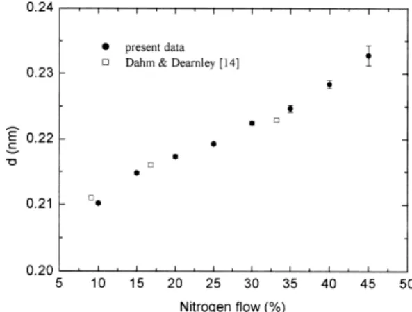
Gaussian peak fitting was used to quantify the
S-Ž .
phase peak in Fig. 4a,b. Although the very large 110 ␣-Fe peak was excluded from the fitting process, its remnant required a second Gaussian to accurately fit the data. The d-spacings calculated from the peak position are plotted in Fig. 6 which shows a steady ‘expansion’ as the nitrogen content in the gas flow was increased, similar to that observed by others. The data
w x
from Dahm and Dearnley 14 are also plotted in Fig. 6 and showed a remarkable similarity to the present data, although the thickness of their coatings were thicker than the present one.
5. Conclusions
Ž .
Nitrided stainless steel coatings AISI-303 cathode deposited at room temperature by dc-magnetron sput-tering on low carbon steel substrates show two modes
Fig. 6. d-Spacings vs. nitrogen flows calculated from fitted peak positions.
( ) G. Terwagne et al.rThin Solid Films 377᎐378 2000 441᎐446 446
of deposition. At low N flows, the metallic regime of2 deposition is predominant and high deposition rates are observed. A nitrogen ‘S-phase’ is formed in the deposited coating and lattice expansion is observed, which confirms the results obtained by Dahm and
w x
Dearnley 14 . The nitrided layers contain a
ferromag-Ž .
netic structure. At higher flows of nitrogen )25% , a compound mode of deposition is observed and the deposition rates decrease rapidly. At these flows, a maximum concentration of approximately 40 at.% of nitrogen was measured in these coatings, which exhib-ited paramagnetic properties. Future investigations will be performed on those samples, as for example, CEMS performed at low temperatures, in order to measure the Curie temperature of the coating.
References
w x1 G. Wagner, T. Louis, R. Leutenecker, U. Gonser, Hyperfine Ž .
interactions 46 1989 501.
w x2 D.L. Williamson, O. Orturk, S. Glich, R. Wei, P.J. Wilbur, Ž .
Nucl. Instr. Methods, B59r60 1991 .
w x3 Th. Briglia, G. Terwagne, F. Bodart, C. Qwaeyhaegens, J. Ž .
D’Haen, L.M. Stals, Surf. Coat. Technol. 80 1996 105.
w x4 D.L. Williamson, J.A. Davies, P.J. Wilbur, Surf. Coat. Technol. Ž .
103᎐104 1998 178.
w x5 R. Wei, Surf. Coat. Technol. 83 1996 218.Ž .
w x6 O. Ozturk, D.L. Williamson, J. Appl. Phys. 77 1995 3839.¨ Ž . w x7 E. Menthe, K.T. Rie, J.W. Schultze, S. Simson, Surf. Coat.
Ž . Technol. 74᎐75 1995 412.
w x8 G.A. Collins, R. Hutchings, J. Tendys, Mater. Sci. Eng. A139 Ž1991 171..
w x9 K. Ichii, K. Fujimura, T. Takase, Technol. Rep. Kansai Univ. 27 Ž1986 135..
w x10 R.G. Vardiman, I.L. Singer, Mater. Lett. 2 1983 150.Ž . w x11 M.P. Fewell, D.R.G. Michell, J.M. Priest, K.T. Short, G.A.
Collins, to be published in Surf. Coat. Technol. w x12 S.D. Dahlgren, Metall. Trans. 1 1970 3095.Ž .
w x13 A. Bourjot, M. Foos, C. Frantz, Surf. Coat. Technol. 43᎐44 Ž1990 533..
w x14 K.L. Dahm, P.A. Dearnley, Surf. Eng. 12 1996 61.Ž .
w x15 B.A. Shedden, F.N. Kaul, M. Samandi, B. Window, Surf. Coat. Ž .
Technol. 97 1997 102. w x16 G. Terwagne, to be published.
w x17 D.L. Williamson, F.M. Kustas, M.S. Misra, J. Appl. Phys. 60 Ž1986 1493..
w x18 Handbook of Vacuum Science and Technology, in: D.M. Hof-Ž .
fman, Eds. , Bawa Singh, John H. Thomas, III, 611. w x19 I. Vincze, I.A. Campbell, J. Phys. F Met. Phys. 3 1973 647.Ž . w x20 J.F. Bobo, H. Chatbi, M. Vergnat, L. Hennet, O. Lenoble, Ph.
Ž . Bauer, M. Piecuch, J. Appl. Phys. 77 1995 5309.