164 pp. 164-178
Shape representation
Corinne LE BUHAN JORDAN *Sushil BHATTACHARJEE *
Frank BOSSEN * Fr6d6ric JORDAN * Touradj EBRAHIMI*
and coding of visual objets in multi-
media applications- an overview
Abstract
Emerging multimedia applications have created the need for new fimctionalities in digital communications. Whereas existing compression standards only deal with the atMio-visual scene at a frame level, it is now neces- sary to handle individual objects separately, thus allo- wing scalable transmission as well as interactive scene recomposition by the receiver. The future MPEG-4 stan- dard aims at providing compression tools addressing these functionalities. Unlike existing frame-based stan- dards, the corresponding coding schemes need to encode shape inforrr~ttion explicitly. This paper reviews existing solutions to the problem of shape representation and coding. Region and contour coding techniques are pre- sented and their performance is discussed, considering coding efficiency and rate-distortion control capability, as well as flexibility to application requirements such as progressive transmission, low-delay coding, and error
robustness.
Key words : Rewiew, Multimedia sercice, Image coding, Geome- trical shape, Edge detection, Information compression, Object oriented method, Standardization, Intraframe coding, ]nterframe coding.
REVUE DES MI~THODES DE REPRI~SENTATION ET DE CODAGE
DE FORMES D'OBJETS VISUELS DANS LES APPLICATIONS MULTIMI~DIA
tgs trame existants, les sch(mas de codage correspondants doivent int@rer l'information de forme. Cet article pr~- sente un certain hombre de sohaions existantes au pro- blOme de la reprgsentation et du codage des formes. Diffd- rentes techniques de codage de formes et de contours sont prgsent@s et leurs performances sont analysdes en consi- d~rant l'efficacit~ du codage et la capacitg de r@ulation d~bit/distortion, ainsi que la flexibilitd vis-gt-vis des besoins de l'application, tels que la transmission progres- sive, le codage it court ddlai, et la rgsistance aux erreurs.
Mots cl6s : Article de synth~se, Service multimedia, Codage image. Forme g~ometrique, D~tection bord, Compression infonnatmn, M~thode orient~e objet, Normalisation. Codage intratrame, Codage intertrame.
Contents
I. Introduction
II. Object shape representation III. Bitmap coding
IV. Intrinsic shape coding V. Chain coding of contours
VI. Geometrical representation methods VII. Temporal prediction
VIII. Performance measure IX. Experimental results
X. General discussion References (46 ref )
R6sum6
Les besoins en matiOre de fonctionalitg orientges objet dans les communications audioviduelIes sont apparus rdcemment avec l'dmergence d'application nouvelles telles que la video confdrence, les viddophones et la vidgo interactive. Alors que les normes de compression exis- tantes traitent la scone audio-visuelle au niveau de la trame, il est maintenant ngcessaire de traiter s@argment les differents objet prdsents, permettant ainsi une trans- mission dchelonnable aussi bien que la recomposition de la sckne par le receveur. La fiaure norme MPEG-4 a pour but de proposer des outils de compression offrant ces nou- velles Jbnctionalitds. Contrairement attx standards orien-
I. INTRODUCTION
The progress in microelectronics and computer tech- nology coupled with the creation of networks with various channel capacities is the basis of an infrastruc- ture for a new era of data processing. Emerging applica- tions such as video conferencing, mobile videophones and multimedia will have a great impact on professional life, education and entertainment.
The digital representation of visual information in its canonical form leads to a huge amount of data. Early work in visual data compression attempted to reduce the amount * Signal Processing Laboratory, Swiss Federal Institute of Technology at Lausanne - EPFL, CH - 1015 Lausanne, Suisse
C. LE BUHAN JORDAN. - SHAPE REPRESENTATION AND CODING OF VISUAL OBJECTS of bits required to present such data. while preserving the
original visual quality as much as possible. Besides trans- torm based methods which use tools for energy compac- tion attemped to achieve this goal object oriented schemes were developed in order to mimic the processing of the human visual system.
More recently, due to the developments in multimedia applications (editing, video games and interactive video, computer generated graphics, etc.) new functionalities such as object manipulation, selective object rendering, different temporal resolution of objects, and so on, are as important as improved compression efficiency. Object oriented coding seems a more natural approach to practi- cal systems as in these applications, the original source material is fl'equently composed of different objects put together in a mosaic form or in a layered fashion.
A major difference between conventional techniques based on energy compaction (such as the well known block based DCT method) and object oriented methods is that in addition to texture (and motion in video), information about the shape of every object has to be encoded and communicated to eventual decoders. Hence, shape coding is a topic of interest in all object oriented techniques. The MPEG-4 standardization activity for multimedia applications has examined various shape coding techniques lbr object oriented coding {36].
In this paper, we discuss major shape coding tech- niques described in literature and review their efficiency for coding of typical objects. The structure of the paper is as follows. Section II outlines the problems tackled by the various shape representation methods used in litterature The major classes of shape coding techniques are also briefly overviewed in this section. Section III describes bitmap-based coding methods, in which shape information is processed as a binary image. Section IV presents two techniques based on an intrinsic shape coding principle, namely, a skeleton-based and a quadtree-based method. Section V describes a popular techniques for shape coding known as 'chain coding' which is based on a contour representation. Variants of the same technique are also described in the same section. By relaxing the losslessness constaint, geometrical representation methods are alterna- tives to chain coding which are also based on contour repesentation but lead to a higher performance in terms of compression efficiency. Section VI presents a number of such geometrical representation methods.
In video coding applications, the temporal correlation between successive instances of the same object may be exploited to enhance the compression efficiency. These techniques are described in section VII. As it is the case in conventional image and video coding, there is no objec- tive measure in order to assess the perceived visual quality of a lossy coded shape. In addition to this problem, the definition of the rate when coding an object in a scene is less obvious when compared to conventional image and video compression. These issues are discussed in section VIII. In section IX, the performance of some of the tech- niques described in this p@er is studied. Conclusions are drawn in section X.
165
II. OBJECT SHAPE REPRESENTATION
The problem of region shape representation has been investigated in the past /'or arbitrary and constrained regions [3,17]. The different representations are closely linked to three major classes of shape representation techniques, namely bitmap, intrinsic and contour based ones. Designed only for compression, bitmap-based techniques apply binary image coding methods, such as those developed for facsimile transmission, to shape images. Intrinsic shape representation methods either decompose the shape into smaller, simpler elements (quadtree-based techniques [17], fractal representation, etc.), or represent it by its skeleton.
FIo. 1.- Different contour representations : (upper-left) 6-connected with crack edges ; (upper-fight) 8-connected ; flower-
left ) 4-connected ; (lower-fight) alternative 4-connected with non-redundant inter-region representation. Diffdrentes reprisentations des contours : (en haut ?: gauche)
6-connectivit~ avec ~, crack edges ~ ; (en haut ?l droite) 8-connectivit~ ; (en bas & gauche) ; 4-connectiviti (en has ?l droite) reprdsentation en 4-connectivit~ sans redondance inter-
r~giovz..
As opposed to the latter region-based methods, contour-based techniques use a transform to convert the object masks into contours, like in the human visual sys- tem. This representation is desirable in applications where a semantic or geometrical description of the shape is used, such as in database applications [34]. For rende- ring, an inverse transform is used to recover the shape. This transformation should preserve inlormation to allow lossless shape coding using contours. When simplifica- tion hypotheses are available, for example if every region is at least two pixels wide, the transformation can often be expressed in a very compact form. Various contour transformations are depicted in Figure 1. There are seve- ral connectivity schemes, which define what relative posi- tions two neighboring contour pixels can take. The two most common schemes are 4-connectivity and 8-connec-
166
tivity. Let i and j be two neighboring contour pixels. In a 4-connected contour, pixel i is either to the north, east, south, or west of pixel j, and in a 8-connected contour it can also be to the north-east, south-east, south-west, or north-west in addition to the previous four directions. Let 0 be the object mask defined as
(1) O~y = I 1 if the pixel located at (x, y) belongs to the [ object, 0 otherwise.
Let N w be the set of pixels neighboring the pixel located at (x,)'i. The contour mask C (A9 is defined as
(2) O3,= / 1 if Ox>, = 1 and 3 (u, v) 9 N such that t Our = 0, 0 otherwise.
For 4-connected contours Nry =
{ (u, v) I max ( l u - x l , Iv-yl = 1} and for 8-connected contours N y =
{(u, t~)l ( l u - x l + I v - Yl = 1}. An alternate connectivity scheme is based on 6-connected contour points. Whereas 4- and 8- connected contour points lie on pixels, 6-connected contour points lie between pixels (crack edges). Although it facilitates handling of thin shape details such as isolated pixels or lines [42], it does not seem to be as popular as 4- and 8- connectivity schemes.
III. BITMAP CODING
Bitmap coding techniques operate on the raw data, without performing any prior transformation. Two such techniques are presented in this section. Both are based on paradigms that have been successfully applied to black and white image coding, and for facsimile appli- cations in particular. The first one is based on run-length encoding and the second on arithmetic coding with conditional probabilities.
III.1. Modified-modified read
(MMR)
The MMR method is based on run-length encoding of a binary image. The image is scanned line by line and the lengths of each black and each white segment are encoded. To improve the efficiency of the method the encoding of the length is optimized by taking into account segment boundaries in the previous line. This algorithm has been successfully applied in the facsimile group 4 standard [25].
An adaptation of this method to shape coding is pro- posed in [46]. Macroblock partitioning is introduced for compatibility with Dot-based texture coding. Further- more a size conversion procedure is proposed to achieve lossy shape coding.
C. LE BUHAN JORDAN. -- SHAPE REPRESENTATION AND CODING OF VISUAL OBJECTS
III.2. Context-based arithmetic encoding
(CAE)
Arithmetic coding [45] is a very efficient entropy coding scheme. Given the probability distribution of symbols in a string, arithmetic encoding can compress the string to a length close to its entropy. The standard application of arithmetic encoding to a binary image is as follows. Pixels of the image are encoded in a predefi- ned scan order, typically raster scan. At each pixel to be coded, the arithmetic encoder is fed the value of the pixel plus a probability distribution. In the case of a binary image, this probability distribution reduces to a single number Po which gives the probability of any pixel being black. The probability of any pixel being white is simply given by 1-Po.
The efficiency of such a representation depends upon the suitability of the probability distrubution that is used. CAE assumes that a high degree of local corre- lation exists in the image. Hence, conditional probabi- lities are introduced. For a given pixel, the probability distribution is conditioned upon the values of the pixels in a local neighborhood [29]. The shape and size of the neighborhood is reprensented by a template (see Fig. 2 for the template used for intra mode coding). The size of the template is typically 10 pixels leading to 1024 different contexts [5]. A context is an integer specifying the value of each pixel within the template. The context is used to access a table contai- ning probability distributions (one for each context). This table is created by a training procedure prior to coding, or in the case of adaptive CAE, it is adapted during the coding procedure as in JBIG [26]. Adaptive CAE is not considered here due to the small size of the images to be coded, which do not allow enough time for proper adaptation.
>(>4>( >( >4>(0
FIG. 2. - 10-pel template used for intra mode coding. The circle represents the current pixel to be coded and the crosses the pixels
belonging to the template.
Voisinage de 10 ~l~ments utilis~ pour le codage intra. Le cercle reprs l'~lement courant ?t coder et les croix les ~I~ments
appartenant au voisinage.
The efficiency of CAE schemes largely depends on the choice of the template. In general, the larger the template, the better, the performance. However, the memory for storage of the probability tables increases exponentially with the size of the template. There is also the risk of over-generalization when using large templates.
In a block-based texture coding environment, the CAE method can be adapted to proceed in a block-based fashion [6].
C. LE B U H A N J O R D A N . - SHAPE REPRESENTATION A N D C O D I N G OF V I S U A L O B J E C T S 167
IV. INTRINSIC SHAPE CODING
Intrinsic shape representation considers the region rather than its boundaries. Such representation methods, also called internal representation methods, were among the first methods to be investigated in the fields of com- puter vision and pattern recognition [3]. In this section, two techniques are presented. They are based on two different approaches to the problem: the first one consists in representing a shape by its skeleton, and the second one is a hybrid block/quadtree decomposition which has been investigated in the framework of the MPEG-4 video compression standardization process.
IV.1. Skeleton decomposition
Skeleton decomposition, also referred to as medial axis transform (MAT) or symmetric axis transform (SAT), has been widely investigated. It consists in describing a full figure by its skeleton. Basically, the skeleton of a shape can be extracted by taking the centres of all maxi- mally inscribed discs. The shape description consists of two parts: the symmetric axis or locus of the centers of these discs and their corresponding radii towards the shape boundary (quench values). Mathematical morpho- logy operators can be used to extract the skeleton and corresponding quench values for any pixel-quantized structural elements (disk, square, cross, etc.) [43]. Since different structural element result in different shape repre- sentations, the element used must be either implicitly known by the decoder or transmitted together with the skeleton and quench values. Shape representation para- meters can be separately encoded by means of run-length coding combined with adaptive arithmetic coding [8].
The cost for transmitting all skeleton points remains too high for practical applications. It is pos- sible to decrease the associated redundancy by introdu- cing a minimal skeleton, which allows the use of dis- connected skeleton points by removing redundant points [33]. Further improvement can be achieved by optimizing the structural element for the shape to be coded. Optimization can be performed at a reasonable cost by means of genetic algorithms [8, 9, 31]. Either the number of skeleton points or the final bitrate after entropy coding may be used as a cost function. It is also possible to maximize the area of the shape resul- ting from the reconstruction by only a few skeleton points. Experiments show a gain of up to 20% in final compression, using such techniques [8].
Skeleton-based shape decomposition is lossless and allows progressive transmission: partial recons- truction is possible from a subset of the transmitted information. Skeleton points with large quench values
are more meaningful than those with smaller values, because they cover a larger image area. Therefore ske- leton points should be transmitted in the decreasing order of their quench values. In practice, the bitstream is divided into different levels of priority, each one corresponding to a subset of quench values. Since the human visual system is sensitive to shape changes as small as one pixel, the method should assign to each progressive level one specific quench value [1, 2 ... k] and all remaining (> k) values to the coarsest level. Entropy coding of the skeleton points is then perfor- med separately for each level, which causes progres- sive transmission to be more expensive than non-pro- gressive transmission. On the other hand, with the proposed quench thresholding, quench information does not need to be transmitted for refinement levels. Experiments on the binary image
girl
using 7 refine- ment levels have shown a moderate increase of about 10% in bitrate compared to non-progressive transmis- sion [8].The method is also stable with regard to transmis- sion errors, since the loss of one skeleton point will only locally influence the shape which can still be reconstructed.
IV.2. Hybrid macroblock / quadtree fl}r binary shape representation
The shape coding method described in [16] is based on a 16 x 16 pixel macroblock partition to facilitate its integration in existing block-based video coding schemes. A block is said to be
uniform inside
if all the pixels in it belong to the region coded, anduniform outside
if all do not. These blocks are sim- ply indicated to the decoder through a simple flag. Each non-uniform block is further recursively split into four square subblocks. The resulting block hie- rarchy is represented in a quadtree. Uniform outside and uniform inside subblocks are tagged as leaves, while non-uniform subblocks are further split. The resulting combinations of outside leaves, inside leaves and split subblocks are described by indices that are entropy coded with Huffman variable length code-words (VLC). In addition, index swapping pro- cedures have been introduced to increase coding effi- ciency [16].Although this technique is instrinsically lossless, filtering the shape before coding can increase compres- sion performance and facilitate rate control. A pre- processing stage is applied to increase the proportion of large uniform blocks which require less bits for coding. One drawback of this approach is the introduc- tion of blocking artifacts along the shape contours. However, these may be reduced by appro- priate post-filtering.
168
V. CHAIN CODING OF CONTOURS
As mentioned in section II, regions may also be represented by their contours. The contour of a region is a connected chain of pixels. In this section, we discuss methods for representing contours by chains of adjacent boundary pixels. Both lossless and lossy representations are discussed.
V.1. Lossless coding
Freeman's chain code [18] may be used to represent contours of regions efficiently. Chain coding is based on the observation that the relative positions of any two adjacent points on a line in a digital image, are restricted to one of eight configurations (four possible configura- tions if 4-connectivity is considered). Thus, from a given point on the line, the transition to the next point can occur in one of eight directions. Each transition from one point to the next is called a link. The chain code for a line is formed by a sequence of links. The chain code
/
representation of a contour is constructed as follows. 1. Select a starting point on the contour. Represent this point by its absolute coordinates in the image.
2. Represent every consecutive point by a link showing the transition needed to go from the current point to the next point on the contour.
3. Stop if the next point is the initial point, or the end of an open contour. In the case of open contours, either a special end symbol may be encoded or the total number of chain symbols may be transmitted prior to the sym- bols.
Such a chain code is referred to as Freeman code. Since every pixel in the contour is represented in the chain code, this method is lossless for encoding contours. Below, we discuss the basic Freeman code and some other schemes derived from it.
V. 1 . 1 . F r e e m a n codes
Freeman codes have been widely accepted as the preferred method for representing contours, as they are highly efficient compared to the naive representation where each point on the countour is represented by a pair of absolute (integer) coordinates. Since a link in a Freeman code represents one of only eight possible directions, a set of eight symbols is sufficient to repre- sent a Freeman-coded contour. The eight directions for the valid transitions may be named East, North-East,
North-West, West, South-West, South, and South-East.
Each of the eight symbols may be represented by a string of 3 bits. Thus, the contour may be encoded in a binary bit-string with 3 bits per link.
C. LE BUHAN JORDAN. -- SHAPE REPRESENTATION AND CODING OF VISUAL OBJECTS
The above Freeman coding scheme is based on the 8- connectivity of contour points. Alternatively, we may choose to represent a contour using 4-connectivity, where only transitions in four directions, namely, East,
North, West, and South are allowed. Thus, a set of four symbols is sufficient to represent contours based on 4-connectivity. This results in a Freeman code costing only 2 bits per link. Ostensibly, this gives us an improve- ment of 33% in coding efficiency. However, empirical results show that Freeman codes using 4-connectivity are, on average, 33% longer than the corresponding 8- connected chains [41]. In fact, 4-connected chains are not efficient to represent diagonal moves, requiring two links where 8-connected chains only use one link. As the geometric resolution of the image increases, 8-connecti- vity becomes more and more efficient compared to 4-connectivity. Hence, 4-connectivity is not commonly used for constructing Freeman codes for contours.
V . 1 . 2 . D i f f e r e n t i a l c o d i n g
Differential chain codes, also proposed by Freeman [19], can offer substantial improvement in encoding effi- ciency, compared to Freeman codes. Our discussion of differential chain codes is based on 8-connectivity. The differential chain code representation for a contour may be constructed based on its Freeman code. Here, each link is replaced by its difference from the preceding link. Mathematically, the Freeman code C of a contour may be considered as an ordered-set of links :
C = { l i } i = 1 , 2 .... N
where l i represents the i-th link in the chain of length N. Let k i = I i - li_ I, for i = 2,3 .... N. We can now define:
k i + 8 if k i < - 3
di= k i - 8 i f k , > 4 k i otherwise
where l i is the i-th link in the differential chain code. (The value of d i is computed modulo 8 for 8-connected chains. Equivalently, the links for the differential chain code corresponding to a 4-connected Freeman code are computed modulo 4.)
Entropy coding may be applied to encode differen- tial chain codes efficiently. The number of symbols required to represent a differentially coded chain is the same as that required for the corresponding Freeman code. However, unlike in the case of Freeman coding, the distribution of the symbols in the differential chain code is not uniform. We can expect the directions repre- sented by two consecutive links in the Freeman code to be similar. Therefore, the difference between the links is generally small. For images with sufficiently fine resolu- tion, most links in the differential chain code have values o f - l , 0, or 1. A suitable entropy based encoding scheme may be developed to exploit this knowledge. A simple Huffman coding scheme can be used, associating a variable length code to different possible symbols. The most likely differential value, 0, will be assigned a
C. LE BUHAN JORDAN, - SHAPE REPRESENTATION AND CODING OF VISUAL OBJECTS 169
single bit codeword and so on [24]. In general, a rate of about 2 bits per link may be expected by using Huftman encoding of differential chain coded contours. Result for this technique are presented in section IX.
V. 1.3. I m p r o v e d e n t r o p y c o d i n g
Several attempts to improve the efficiency of diffe- rential chain codes have been reported in the relevant literature. These methods usually rely on specific know- ledge about the characteristics of the contours (or lines) in question, in order to establish thighter upper-bounds on the entropy of the corresponding differential chain codes. This leads to improved efficiency in entropy- based encoding.
Kaneko and Okudaira [27] proposed an algorithm for coding smooth contours, in which the contour is first divided into a sequence of segments. Within a segment, each link must be in one of the two adjacent directions, thus only requiring one bit per link. The length and the dominant direction of the segment must also be trans- mitted. The smoother the contour, the longer the seg- ments, and hence, the higher the encoding efficiency. For the case of rough contours, the average length of each segment is small. In such cases this method offers about the same efficiency as the method described in section V. 1.2. For example, for a contour where the average segment-length is 3.4 links, the authors quote a coding rate of 2.02 bits per link. However, in another example, where the average segment-length comes to 16.5 links, the coding rate is 1.38 bit per link.
Eden and Kocher [15] have proposed an encoding scheme in the context of 4-connected Freeman coded contours. Their method is based on a first-order analysis of 4-connected contours. They introduce three symbols to represent different combinations of pairs of adjacent links :
left turn,
andstraight ahead.
These three symbols are used to represent the 4-connected contour. The resulting entropy for a contour with N points is N log 2 (3). Note that, expect in the case of very short contours, a right turn is never followed immediately by another right turn. The same can be said for left turns. Using the constraint that consecutive turns of the same type should never occur, Eden and Kocher reduce the bitrate per link from log 2 (3) down to log 2 (1 + V~).Lu and Dunham [32] use Markov models to describe the structure of the chains. The differential chain code is considered as a Markov source, and is encoded using an entropy based encoding scheme. The transition probabi- lities pertinent to the chosen Markov model are compu- ted experimentally. These probability values are used to construct appropriate entropy based encoders. Using a Huffman encoding scheme based on a second-order Markov process, they achieve encoding rates similar to those obtained using the method of Kaneko and Okn- daira, described above. However, the Markov model based scheme is simpler to implement. They show that significantly better encoding rates can be obtained by using an arithmetic encoding scheme [40] based on a
second-order Markov model. On average, this method performs about 25% better than the simple Huffman encoding scheme for differential chain codes.
Extending the latter approach to adaptive, higher order Markov models, chain coded contours can be efficiently compressed using
prediction by partial matching (PPM)
[4, 11]. PPM is a finite-context statistical modeling tech- nique (also referred to as a fixed-order, finite-context Mar- kov model), that blends together several fixed-order context models to predict the next link in the contour. Pre- diction probabilities are computed from frequency counts, which are updated as links are processed. The link that actually occurs is encoded relative to its predicted distri- bution, using arithmetic coding. Although predictions generally get more accurate as more links are processed, they are not guaranteed to do so. This technique can be applied to either Freeman or differential codes. In the results shown in section IX, the former have been used, since it has been empirically found that they yield higher efficiency. Markov-modeled arithmetic coding methods perform well mainly because the probability estimates are very well suited to the data at hand. However, the additio- nal cost of storing, and eventually maintaining the transi- tion tables must also be taken into account.V.2. Lossy schemes
The chain coding methods discussed in section V. 1. are lossless, as the encoded contour can be reconstruc- ted exactly. At the expense of accuracy, some encoding efficiency may be gained by using a lossy chain coding method or by pre-processing the shape to make its contours smoother and consequently facilitate its chain coding.
A lossy chain coding method called
multi-grid chain
code
(MMC) has been recently proposed by Salembier, Marques and Gasull [24,42]. The MMC is based on the so calledhexagonal grid,
or 6-connected crack edge struc- ture as mentioned in section II. By exploiting its specific grid structure, the technique gathers consecutive transi- tions together and exploits the corresponding introduced decoding ambiguity to yield a slightly lossy representa- tion. According to the authors, the loss is negligible and the performance is better than the simplified 4-connec- ted Freeman differential coding (three symbols).Another method for producing a compact chain code description consists in simplifying the chain code so that only one pixel forward moves are allowed [24]. This technique requires 8-connectivity to be used and is not suited to represent shapes with high curvature. It yields a subsequent simplification since only three symbols are needed to represent the corresponding differential code in 8-connectivity.
One way to improve the performance of lossless chain coding schemes without adapting the correspon- ding algorithms consists in pre-processing the shape.
170 C. LE BUHAN JORDAN. -- SHAPE REPRESENTATION AND CODING OF VISUAL OBJECTS
Smooth contours are indeed cheaper to encode. More- over, a pre-filtering step is particularly relevant for noisy masks obtained from an imperfect former segmentation stage. Various filters may be used, such as a median fil- ter, a morphological open-close-close-open filter, or the majority filter introduced in [22].
VI. GEOMETRICAL REPRESENTATION METHODS
Shape boundaries can be approximated by a 2-dimen- sional representation. Compression is achieved by trans- mitting only a set of representative vertices, which are then used to reconstruct the contour via line or spline seg- ments. Geometrical approximation methods are usually lossy, and allow simple distortion control by constraining the geometrical representation accuracy to a maximum allowed error. Several geometrical representation methods exist based on different vertex selection, curve reconstruction and entropy coding approaches. Whereas entropy coding constitutes a relatively independent pro- blem, vertex selection and curve reconstruction are clo- sely linked, vertices being optimally selected with regard to a specific geometrical reconstruction model.
VI.I. Polygonal approximation
rithms, which do not only split but also merge segments, have been developed [1, 38]. A review of polygonal approximation methods is given in [14].
C B
F i g 3. I t e r a t i v e v e r t e x s e l e c t i o n . Sdlection itdrative des sommets.
Efficient schemes encode only the position of the first vertex in absolute coordinates. The subsequent vertices are differentially coded, relative to the previous vertex. To actually improve compression, entropy coding is used. When the maximum allowed error is large, only a few vertices are needed. Their positions are usually not highly correlated, and entropy coding does not improve compression performance. When the maximum error is small, the vertices are numerous, and close to their neighbors. Entropy coding then becomes more efficient. In the limit, when the error is set to zero, polygonal approximation becomes very much like chain coding, and corresponding entropy coding schemes may be used.
Polygonal approximation is the simplest geometrical approximation, where only the positions of the vertices need to be encoded. Since digital images are sampled on a finite grid, a lossless representation can be achieved for any shape, corresponding to the removal of interme- diate contour pixels in contour straight lines: in the worst case where no straight lines exist in the shape boundaries, all contour pixels are polygon vertices. The ploygonal approximation encoding process consists of contour extraction, vertex selection and vertex coding. The decoding process requires vertex decoding followed by a polygon filling procedure [17].
In the context of data compression, the polygonal approximation which has the least number of vertices, and which conforms to a predefined error criterion, is gene- rally considered as the optimum. Different error criteria may be used to measure the approximation quality [39]. A simple, sub-optimal, vertex selection algorithm based on iterative refinement was originally proposed in [13, 37]. The first approximation is given by the main axis of the shape, which is the longest segment between any two contour pixels. This approximation is recursively refined by inserting a new vertex on the contour point which is furthest away from the current approximation. This vertex insertion procedure stops when the distance between the approximated contour and any contour pixel is smaller than a given threshold (Fig. 3). More sophisticated algo-
Vl. 2. Higher order approximations
A higher order geometrical representation can be provided by cubic curves interpolation. To reconstruct the approximated curve between two vertices, two constraints, such as derivatives or control points, are considered in addition to the coordinates of each end- point. The resulting approximation is smoother and is visually more pleasant. However, it is not well suited to represent sharp angles.
VI. 2. 1 Higher order approximation schemes
A contour coding method based on approximation by blending curves was proposed in [44] to achieve rate-distortion optimization for a region-based coding scheme. The number of vertices is constrained by the available rate budget. Vertex positions are calculated in order to minimize the approximation distortion. Any distortion measure may be used. A popular one is the maximum local error defined as the distance between the original contour and the spline. Initially, the corres- ponding vertices are equidistantly distributed along the contour to be approximated. A steepest descent optimi- zation technique, consisting in successively perturbing
C. LE BUHAN JORDAN. - SHAPE REPRESENTATION AND CODING OF VISUAL OBJECTS 17l
each vertex along the eight possible directions, is then applied. For each possible move, the four splines affec- ted by the perturbed vertex are updated, and the corres- ponding error is computed. The position minimizing this error is retained. The algorithm is iterated until the error drops below a predefined threshold.
The algorithm minimizes the error for only one vertex at a time and the final solution is generally suboptimal. Moreover, whereas the algorithm requires a predefined number of vertices, no method is proposed to adapt the number of vertices to shape features. In [44] the contour optimization is carried out for different numbers of ver- tices and the solution minimizing the rate-distortion crite- rion is chosen (rate and distortion being defined in that case with regards to the whole region-based video coding scheme, not only the shape coding module).
Another method uses Hermite curves [17] to approxi- mate the contour [21]. At each vertex the tangent of the reconstructed curve is constrained by the tangent of the original contour. Vertices are recursively selected accor- ding to a scheme similar to the ones used for polygonal approximation. As opposed to the former method that constrains the rate, this method constrains the distortion.
V I . 2. 2. Hybrid polygonal / cubic representation
Polygonal approximation is not suitable for smooth shapes, whereas cubic curve approximation cannot repre- sent sharp edges. Therefore, a hybrid polygonal/cubic approximation is expected to be more efficient [20]. Basi- cally, two approaches are possible: either the polygon / curve switch and the encoding of the corresponding one bit flag are clone at vertex level, or at region level, relying on the assumption that object shapes are likely to be best described either by smooth curves only or distinct angles only, not by a combination of the two. With regard to the curve or polygon only approximations, the latter scheme requires only one additional bit for each region while exploiting the advantages of both techniques. Moreover, both schemes require the implementation of a decision scheme, either at a global or at a local level. In practice, both approximations are considered and the better one is used. However, this raises dependency problems when a local switch is to be applied, since spline and polygonal approximation methods do not share the same vertex selection procedure.
blocks which contain at least one contour pixel. New control blocks are iteratively added until one of the fol- lowing conditions is met: (i) the number of control blocks has reached a predefined maximum; (ii) the total error is lower than a given threshold; (iii) the insertion of new control blocks does not decrease the error any- more. At each iteration, the newly inserted control block is the one that maximizes the error decrease, among block candidates.
When reconstructing the curve, the norm of the tan- gent vector is scaled between the two endpoints. If two successive control vertices are far apart, the tangent constraint is tight, whereas if the vertices are close, the constraint is loose. The maximum curvature of the reconstructed contour can therefore be controlled roughly. For efficient coding, the following algorithm is used. First the number of possible line segments within a control block is reduced using vector quantization [35]. The resulting codebook contains 16 entries, and thus 4 bits are needed to encode the line segment. Then the position of a control block is coded relatively to its pre- decessor. A small number of bits is used to do so. If two blocks are too far apart, an escape code is used, and the absolute position of the next block transmitted. Further compression gains may be achieved by the use of entropy coding.
The accuracy of this method is limited by the size of the bothblock and the codebook. However, some modifi- cations can be undertaken to enhance the quality of the reconstruction. One possibility is to allow two control ver- tices and tangent vectors in a block, and another is to increase the polynomial degree of the reconstructed curve. Similarly a method for representing sharp angles could be used to permit quasi-lossless or lossless re-construction. Also, the control block selection process can be improved by using more powerful optimization techniques such as genetic algorithms, but at the cost of speed.
To a certain extent, this technique enables progres- sive transmission. First only a carefully chosen subset of all control blocks is transmitted, and then each new transmitted block refines the contour.
VII. TEMPORAL PREDICTION
V I . 2 . 3 . Joint block / Hermite curve representation
The novel method proposed here is based on a 8 X 8 pixel block partition and approximates contours using Hermite curves. Only control blocks contain informa-
tion to reconstruct the curve, by defining a vertex and a tangent vector using a line segment. For each control block, this line segment is defined to be the one which matches most accurately the contour within the block.
A greedy algorithm is used to select the control blocks. It starts with a pair of fixed control blocks taken from the list of all possible control blocks, that is, all
Shape coding techniques presented so far do not take advantage of temporal redundancies in the scene. In the framework of video sequence coding, it is important to also reduce temporal redundancy in the bitstream, shapes remaining very similar from frame to frame.
The potential drawback of any temporal prediction scheme is that to decode the k-th frame, the k - 1 pre- vious ones need to be decoded first. A solution to this problem is to code every f-th frame without temporal references. According to the needs of the application, a tradeoff must be found between high compression ratios (largej') and fast random access (smallj'),
172
VII.1. Motion based prediction schemes
C. LE BUHAN JORDAN. -- SHAPE REPRESENTATION AND CODING OF VISUAL OBJECTS
Similar to texture prediction, shape prediction from frame to frame can be achieved by means of motion estimation and compensation techniques. A general motion model would handle shape rotation, scaling and projection. Several shape representation methods inva- riant to scaling and rotation have already been investiga- ted [38]. If such a method is applied for intra-frame shape coding, only motion model parameters need to be transmitted to predict the shape in the next frame,
In practice however, when shape coding is pert'or- med in a complete shape-motion-texture coder, a scheme consistent with that of texture coding may be used to simplify the overall algorithm. The main diffi- culty lies in the dependency between shape, motion and texture coding. Motion and texture coding are expected to be more efficient when using shape data. This is the idea behind second generation coding techniques [28]. Temporal shape coding has been investigated mainly in the framework of region-based coders, where a spatio- temporal segmentation and tracking algorithm extracts a set of regions coherent both spatially and temporally [2,8]. In this case, each region is tracked along the sequence, and can therefore be temporally predicted from its previous instance. Shape prediction error results in a set of error regions for which shape or contours can be encoded by one or several methods, for instance chain or skeletons [8].
In block-based coders adapted to perform object sca- lability, the environment is quite different. The shape to be coded does not necessarily correspond to a uniform region, but rather to a preselected object from the scene, possibly including several subregions. Segmentation is performed semi-automatically based on semantic infor- mation (for instance the number of expected objects, as in [21]), or is available from the image composition stage (blue screening technique). Motion and texture coding remain block-based, but use shape masking to improve their performance on object boundaries [10, 36]. In this case, when lossy shape coding is performed, the reconstructed shape must be available to perform motion estimation (only pixels within the shape in the block will be considered). Shape temporal prediction must then use either former texture-based motion infor- mation, or specific motion vectors that need to be trans- mitted.
Considering the afore mentioned statements, the CAE technique can be straightforwardly extended [6] to the inter mode case to take advantage of the correlation bet- ween two successive masks. Given a motion compensa- ted version of the previous mask, a modified template may include pixels from it, as shown in Figure 4. Simi- lar steps have been applied to improve the MMR method as well [46].
Vertex-based methods can be adapted to provide inter frame coding without too much effort. In a block- based coder, prediction can be performed from the pre-
vious shape, by exploiting available motion information. This motion can be either specifically computed for shape information, thus requiring the corresponding parameters to be encoded, or extrapolated from the tex- ture motoin vectors from the previous frame. Each ver- tex is then motion compensated and the corresponding error with regard to the contour to approximate is com- puted. If the error is lower than the predefined threshold, the vertex is retained, otherwise it is rejected. The retai- ned vertices constitute a rough polygon to which the ite- rative refinement technique presented in section VI is applied. The vertex positions in the old and new lists of vertices are then encoded, for instance by means of a run-length coding method. Inserted vertices may also be encoded using adaptive arithmetic coding [12, 20].
XI"
Fig 4 . 9 - p e l template used for intermode coding. The right side of the template represents pixels from the current mask and the left side pixels from the previous motion compensated mask. The
arc defines the alignment of both masks.
Voisinage de 9 ~Hments utilisd pour le codage inter. La pattie de
dtvite reprdsente les dliments de l'image courante et celle de gauche les ~liments de l 'image pr&~dente apt'ks compensation de
mouvement. L'arc ddfinit l'alignement entre les deux parties.
Another possibility consists in coding the shape pre- diction error as a shape image. However, since the cor- responding regions are expected to be small, the corres- ponding cost may be higher. Thresholding may be used to eliminate meaningless regions. The tolerance error should be adapted to a value different from that used in inna-coding. Similarly to motion/texture coding schemes, in case no matching is possible, for instance when no motion vector resulting in an acceptable pre- diction error can be found the shape is coded in intra mode.
VII.2. Entropy based prediction schemes
An alternative temporal prediction technique which does not use any motion information while remaining lossless may be used at the entropy coding stage. When sophisticated models are used to code the chain code symbols describing the shape, it is possible to exploit the experience gained from a previous flame to entropy code the current frame by maintaining the model from frame to frame, instead of resetting it after each frame.
As an illustration, in the context of chain coding using fixed-order, finite-context Markov models for arithmetic coding (see section V. 1.3), there exists a
C. LE B U H A N J O R D A N . - SHAPE REPRESENTATION A N D C O D I N G OF V I S U A L OBJECTS 173 simple solution to exploit temporal redundancies to
increase compression ratios. Instead of resetting the pro- bability tables before each frame, the same tables can be used throughout the sequence. The cost of the first frame is the same as without exploiting temporal redundancies, but the cost of the subsequent frames decreases rapidly.
V I I I . P E R F O R M A N C E M E A S U R E
Bitrate evaluation for contour coding techniques is often provided in terms of the average number of bits per contour pixel, or per link as mentioned in section V. Such a measure depends on the contour definition, and the chosen connectivity. Comparaison with other, non contour based, techniques is therefore difficult. Further- more, it does not show how many bits are actually neces- sary to encode the shape information of a given region, which may be critical in low bitrate applications. In the applications considered here, shape coding is not the final goal; its bitrate should be considered in the context of a complete shape-motion-texture coding scheme.
As is the case with the texture coding quality mea- sure, a shape distortion measure is not easy to define objectively. The human visual system is very sensitive to edges, and errors in reconstructed shapes are far less acceptable than imperfect textures. If the shape is coded in a lossy fashion, imperfect boundary reconstruction may result in an annoying mixed background/foreground at the object borders. However, this argument is mainly valid for hybrid synthetic/natural image coding, where a perfect object mask can be obtained from computer- based object synthesis. Segmentation of natural images is not as perfect and usually provides noisy masks for which the use of lossy coding may be necessary, for ins- tance by prefiltering the shape before coding.
An objective distortion measure requires the compari- son between the original and reconstructed shapes. The comparison may be based on either the contour informa- tion, or the mismatched area. A contour-based error mea- sure is more natural in contour coding methods, especially those minimizing an error criterion (geometrical represen- tations). The distance from the original curve to the recons- tructed curve needs then to be computed. Since no mathe- matical description of the original curve, quantized to a pixel-based 2D grid, is available, the error must be experi- mentally computed as a pixel-to-pixel distance. This allows an easy definition of the local error, such as the peak absolute deviation between two curves, but does not facilitate a global error measure. On the other hand, the number of mismatched pixels between the original and the reconstructed shape provides a global error measure, possi- bly scaled by the original shape size, but does not provide any local error information [30]. Yet the latter error mea- sure offers the additional advantage that it is valid for any shape or contour representation method, and will therefore be used for performance comparison pro'pose in this paper.
IX. E X P E R I M E N T A L R E S U L T S
Simulations have been performed on a representa- tive subset of MPEG-.4 video test sequences:
9 A k i y o sequence, speaker layer, QCn~ (176 x 144 pixels per frame), 10 Hz. This sequence is a typi- cal video-telephony sequence: smooth and tempo- rally stable head-and-shoulders image.
9 H a l l sequence, right man layer, QCtF, 10 Hz. The region of interest is a man carrying a monitor in a hall way. The man walks towards the camera. The corresponding shape is small with sharp meaning- ful details and some tiny holes.
9 C h i l d r e n sequence, logo layer, QCIV, 10 Hz. This is a logo sequence ("MPEG-4 world"), with translation and scaling. It contains many meaningful details.
9 B r e a m sequence, fish layer, QCrF. 10 Hz. The object of interest is a computer generated swim- ming fish with a smooth shape. Motion is complex (shape deformation).
The following shape coding techniques have been investigated:
9 Context-based arithmetic encoding, as per MPE6-4 verification model version 7.0 [36], that is a macro- block-based implementation including motion esti- mation and compensation.
9 Differential chain code. A simple Huffman coding scheme is used to encode differential 8-connected links. This technique has been applied to original frames (lossless) and morphologically filtered shapes.
9 Chain code with PPM entropy coding. This tech- nique has been applied to original frames (loss- less), morphologically filtered shapes, and quad- tree-rounded shapes. To obtain the best possible results, the order of the Markov model has been fine tuned separately for each simulation.
9 Hybrid macroblock/quadtree representation with different truncation parameters, as defined in the former MPEG-4 verification model version 2.0 [23]. 9 Polygonal approximation with fixed-length
coding. Since no vertex entropy coding was used, further improvement can be obtained by applying differential and arithmetic coding to the vertex coordinates [20].
9 Joint block/Hermite curve approximation. Itera- tion is stopped when a predefined number of control blocks is reached (40 in the presented results). The technique is not applied to H a l l and
C h i l d r e n because the corresponding shapes contain meaningful details smaller than the chosen block size (8 • 8 pixels).
The corresponding rate performances, measured as the averaged number of bits per frame for the sequence, are presented in Tables IV to VIII for different distortion constraints. Shape images are first cropped to their cor-
1 7 4 C. LE B U H A N JORDAN. - SHAPE REPRESENTATION AND CODING OF VISUAL OBJECTS
responding bounding boxes extended to multiples of 16 pixels, as defined by the MPZa-4 verification model [36].
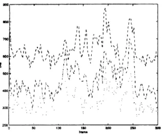
Figure 5 to 11 plot the rate distribution on the ~ream
sequence for each technique. The bitrate values should be compared with the original non-compressed data size (one bit per pixel), as well as with the performance of a simple Lempel-Ziv entropy coding algorithm directly applied to the shape images (Unix compress command). The corresponding measures are provided in Table IX.
t l
I I I I
i I I I I I I I r i
$ g I I ~ i I . I P 9 I / t + r I I I t l I I i $ Iii i l l I ~ i ,~k i #v I~111 i,I 111 I I I ; i , , I~ f ,~
t , ~ ,,,
~,:
~,,,,,,, , ' +~ , , ' i : . , ~ , , t, . . ;. : tr; , 9 ," ' k ~ ~! l " . . i + , 9 +1 1~ "" , . . I "2eA ~ 1 ~Fig 5. c,kE method with temporal prediction, rate performance for lossless and lossy shape representation.
Mdthode CAE avec prediction temporelle, performance en compression pour des reprdsentations sans et avec pertes.
~ 4 + ~ m Ib~h V O P , O~e+eP~l~l+ c h l l ~ c o d ~ g , b i l r a l e
v'A
+
t . . . : ' . , . i # : + ::"iI
"".+
4so " " ! i ~ 0 0 0 5 0 1 0 0 I g O 2 0 0 ~ 3 0 0Fig 7. Differential chain coding, rate performance for lossless and pre-filtered shape representation.
Codage diff~rentiel de cha?nes, performance en comptession pour des representations sans pertes et apr~s pr~fiItrage.
1203
Ortqu'~ fiztt VOP. M a d t o v - ~ t ~ l ~b'~ chm~ ~ " ~ , bi~=le
1 700 eO~ 5CO 4 0 0
f
.... I.ry!:
4
llnme~ VOP, MP E~I-4 Vlil2,0, bk'~lo 'I~IO0 _., I o . ~ " - - " ' z ~ ..LV:: ' / - - ~ . ~ 1 ~ : 4 % 9 -1 1 ~ l " ~ I ,', ~ + - . + ; + i + ~ i " \+ l ~ J
]
2'SO 300Fig 6. Hybrid quadtree/macroblock representation
(MPEG-4 video VM2.0), rate performance for various error thresholds.
Pelformance en compression pour la technique hvbride
arbre quaternaire/macro-bloc (modkle de v~rification MPEG-4 viddo v2.0).
ANN. "I~I~COMMUN., 53, n ~ 5-6, 1998
Fig 8. Markov-modeled intra chain coding, rate performance for lossless and pre-filtered shape representation.
Codage intra de cha~nes par un moddle markovien, performance en compression pour des reprdsentations sans pertes
et aprOs pr~filtrage.
+:I
7 ~ _ L U~
l - - MPEG-.4 VM llt~t, t~'x,,+10~4 S m i t+ 9 9 .' ") . . is 9 +m ' " . , " ... ; ,]'+5 " & " / ' , '. I ( t , + - . . . . I I 2 0 0 ... ~0 1011 150 2 0 0 2 5 0 ~ 0Fig 9. Markov-modeled inter chain coding, rate performance for lossless and pre-filtered shape representation and prediction.
Codage temporel de chafnes par un modOle markovien, pelfonnance en compression pour des reprdsentations sans pertex
et aprks prdfiltrage.
C. LE BUHAN JORDAN. - SHAPE REPRESENTATION AND CODING OF VISUAL OBJECTS
aoo~
lf,~l
Bream ~am VOP, I%t/gon~l e~o,-ox~t~n
B § + 4 - ~" § _ . .+ . " . : " , ~ 4~ # ' . + ~ : " ++ +++ . + .;q ,t. + + A- + + 2 .# - . - . ~ max = 0.5 + + + + i - r I ~ t m U t ~ 1.5 "i i .... ~a, t iff~.~o " "" I _. ~ i i . . . t l I 50 100 150 2OO 2SO 300
Fig 10. Polygonal approximation, rate performance for various error thresholds.
Approximation par polygones, performance en compression pour diff~rents seuils d'erreur.
B ~ s c ' n ~*h VOP, j o ~ bk>c~ a n t t P t ~ t m ~ l x l g " m m ~ l approximation 550 ; , , 500 480 400 350 300 250 2OC . . . . ~ - go ;o io a, , ~
Fig 11. Joint block/Hermite polynomial approximation, rate performance, 40 control blocks.
Approximation conjointe par blocs et courbes de Hermite, performance en compression pour un nombre de blocs de
contrg~le fixd ~ 40.
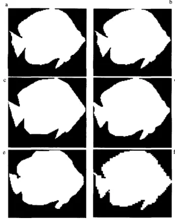
Objective distortion measures are provided for diffe- rent lossy schemes in Table X. The resulting distortion can be visually evaluated for the 102nd frame of the
B r e a m sequence in Figure 12. The morphological filter
appears to allow the most faithful reconstruction. Howe- ver, it is not suited for shapes with small meaningful details, such as Hall and Children. T h e quadtree trunca- tion process results in specific blocking artifacts. Since polygonal approximation splits the contour into straight lines, the reconstructed contour is not smooth. On the other hand, Hermite spline approximation based on control blocks preserves the contour smoothness, but results in a raw approximation of the shape due to its incapability to represent sharp corners (such as the tail of the fish) Although CAE uses a down-sampling / up-
175 sampling scheme for efficient compression, the recons- tructed shape is fairly smooth, thanks to a filter which is applied after up-sampling.
a b
Fig 12. Comparison of the visual distortion yielded by different lossy schemes, Bream sequence, fish layer, frame r 102. (a) original QCIF bounding box (b) MPEG-4 truncation process (c) polygonal approximation, dmcL,= 2.0 (d) morphological filter
(e) joint block/Hermite curve approximation (f) Quadtree truncation process, threshold =1024.
Comparaison de la dislorsion visuelle g~nOrde par diff&ents modes de codage avec pertes, sdquence Bream, image ~e 102. (a) rectangle engIobant original en QCIF (b) mithode d' arron&
MFEG-4 (C) approximation par polygones, dma ~ = 2.0 (d) fiItrage morphologique (e) approximation conjointe par blocs
et courbes de Hermite (f) mdthode d 'arrondi de l "arbre quaternaire, seuil = 1024.
At high threshold values the quadtree pre-processing method may also be exploited by PPM chain coding, which is able to model the specific right turns introdu- ced by the blocking effect. However, this truncation pro- cess is not suited for the 8-connected differential chain code that associates low probabilities to the right angles Since the lossy truncation pre-processing is grid-based, the resulting blocking artifact at the shape boundaries is visually annoying In addition, it is not stable over time, and results in annoying blinking effect in the shape video sequence
Block-based shape coding is generally more expensive than frame-based schemes The lossless compression per- formance of the quadtree method is much lower than the chain coding performance, and the low bitrate obtained for the joint block/Hermite curve approximation method is reached at the cost of a relatively high distortion
176
Table I: MPEG-4 video VM v7.0 p e r f o r m a n c e (CAE method) without temporal predict!on.
Performance du VM MPEG-4 vZO (m~thode CAE) sans prddiction temporelle
rate (bits) Lossless
C. LE BUHAN JORDAN. - SHAPE REPRESENTATION AND CODING OF VISUAL OBJECTS Table VII: Polygonal a p p r o x i m a t i o n performance.
Performance de l'approximation par polygones.
Threshold = 32 [ Threshold = 64 Akiyo 601 518 380 Bream 785 660 494 276 1924 Hall 263 198 1915 1641 Children I
rate (bits) [ Lossless Akiyo 2210 Bream 2639
Hall 725
Children 8220
dist max = 0.5 I dist max = 1.0 dist max = 2.0 [
1221 412 190
1326 530 309
482 256 153
5657 3016 2197
Table II: MPEG-4 video VM v7.0 p e r f o r m a n c e (ChE m e t h o d ) with temporal prediction.
Performance du VM MVeO-4 v7.0 (mdthode CAE) avec prediction temporelle
rate (bits) Lossless Threshold = 32 Threshold = 64
Akiyo 293 194 180
Bream 640 458 337
Hall 241 221 145
Children 561 493 376
Table III : Hybrid quadtree/macroblock (MPEG-4 video VM v2.0) performance.
Performance de la mdthode hydride arbre quaternaire/macro-bloc (VM MPEG-4 V2.0)
rate (bits) Lossless THqt = 32 THqt = 64
Akiyo 1438 1216 714
Bream 1520 1147 675
Hall 425 221 184
Children 3093 2487 1379
Table VIII : Joint b l o c k / H e r m i t e curve representation performance.
Performance de la repr&entation conjointe pat" blocs et conrbes de Hermite.
rate (bits) Akiyo Bream
max control blocks 40 386
379
Table IX: Original and L e m p e l - Z i v c o m p r e s s e d shape b o u n d i n g boxes size.
Tailles des rectangles englobants originaux et compress&" par l'algorithme de Lempel-Ziv.
I r a t e ( b i t s ) [ original bounding box [ LrNIX compressed I Akiyo Bream Hall Children 18437 12484 1627 6607 5300 4783 no gain 5874
Table IV: Differential chain coding performance.
Performance du codage de cha~nes diff&entiel.
rate (bits) Lossless Morphological
Akiyo 679 660
Bream 685 623
Hall 274 217
Children 2390 1660
Table V: M a r k o v - m o d e l e d intra chain performance.
Performance du codage intra de cha~nes avec modkle markovien.
I
rate (bits) Lossless Morphological VM2.0 Thqt= 1024 I
Akiyo 516 450 424 B ream Hall Children 685 300 2255 639 188 1651 591 239 2176
Table VI: M a r k o v - m o d e l e d inter chain coding performance.
Perfolrnance du codage temporel de chafnes avec modkle markovien.
1 rate (bits) Lossless Morphological VM2.0 Tqt = 1024 ]
Akiyo 309 253 209
Bream 485 404 354
Hall 245 122 158
Children 1098 755 1046
Table X: Distortion results for various l o s s y schemes.
Mesures de distorsion pour diff&entes mdthodes avec pertes.
Distortion AKIYO BREAM HALL CHILDREN
Morphological 0.0004 0.0047 0.0588 Quadtree th = 256 0.0038 0.0096 0.0346 Quadtree th = 1024 0.0224 0.0307 0.1465 pol. dist = 0.5 0.0014 0.0035 0.0119 pol. dist = 1.0 0.0072 0.0132 0.0657 pol. dist= 2.0 0.0179 0.0279 0.1433 block/Herrnite 0.0386 0.055 not av.
0.2393 0.075 0.3181 0.0635 0.1881 0.3053 not av.
In the case of polygonal approximation, it should be noted that when the tolerance distance increases the bitrate decreases, but the corresponding gain becomes less important at high error values (flat part of the rate / distortion curve). For the ChiMren logo, the coding cost to represent a lot of short, highly curved contours is so important that the final lossless bitrate is higher than the original shape size. In such a case, the overhead requi- red by a contour representation becomes very important, and also explains the relatively poor performance of chain code methods on such shapes.