HAL Id: tel-01469693
https://tel.archives-ouvertes.fr/tel-01469693
Submitted on 16 Feb 2017HAL is a multi-disciplinary open access archive for the deposit and dissemination of sci-entific research documents, whether they are pub-lished or not. The documents may come from teaching and research institutions in France or abroad, or from public or private research centers.
L’archive ouverte pluridisciplinaire HAL, est destinée au dépôt et à la diffusion de documents scientifiques de niveau recherche, publiés ou non, émanant des établissements d’enseignement et de recherche français ou étrangers, des laboratoires publics ou privés.
Data dissemination protocols and mobility model for
VANETs
Bin Tian
To cite this version:
Bin Tian. Data dissemination protocols and mobility model for VANETs. Other [cs.OH]. Université Blaise Pascal - Clermont-Ferrand II, 2016. English. �NNT : 2016CLF22739�. �tel-01469693�
N° d’ordre : 2739 EDSPIC : 773
UNIVERSITÉ BLAISE PASCAL - CLERMONT ІІ
ÉCOLE DOCTORALE DE
SCIENCES POUR L’INGÉNIEUR DE CLERMONT-FERRAND
Thèse
Présentée parBin TIAN
Pour obtenir le grade deDOCTEUR D’UNIVERSITÉ
Spécialité : INFORMATIQUE
« Protocole de Dissémination de données et Modèle de
Mobilité pour Réseaux Ad hoc Véhiculaires »
Soutenue publiquement le 17 Oct. 2016 devant le jury :Directeur de la thèse : Prof. Kun Mean HOU
Membres du jury :
Mme. Edwige Pissaloux (rapportrice) M. Fabrice Valois (rapporteur)
M. Haiying Zhou (rapporteur) M. Jean-Pierre Chanet (invité) Mme. Jianjin Li (member du jury) M. Alain Quilliot (président du jury) M. Christophe de Vaulx (invité)
N° d’ordre : 2739 EDSPIC :
UNIVERSITÉ BLAISE PASCAL - CLERMONT ІІ
ÉCOLE DOCTORALE DE
SCIENCES POUR L’INGÉNIEUR DE CLERMONT-FERRAND
Thèse
Présentée parBin TIAN
Pour obtenir le grade deDOCTEUR D’UNIVERSITÉ
Spécialité : INFORMATIQUE
Data Dissemination Protocols and Mobility Model for VANETs
Soutenue publiquement le 17 Oct. 2016 devant le jury :
Directeur de la thèse : Prof. Kun Mean HOU
Membres du jury :
Mme. Edwige Pissaloux (rapportrice) M. Fabrice Valois (referee)
M. Haiying Zhou (referee)
M. Jean-Pierre Chanet (guest jury) Mme. Jianjin Li (jury member) M. Alain Quilliot (jury member) M. Kun Mean HOU (supervisor) M. Christophe de Vaulx (guest jury)
This thesis is dedicated to my parents for their love and support.
此文献给我最爱的父母
Acknowledgement I
Acknowledgement
First, I would like to thank my thesis supervisor, Prof. Kun-Mean HOU, for his trust, help, and guidance. I really appreciate it. Every discussion between us means a lot to me while every suggestion from him is valuable to me. Then, I want to thank Prof. Hong Sun of Wuhan University for providing me a chance to start a new research life in France. Next, I very appreciate Prof. Alain Quilliot for his cares and concerns during my studying In LIMOS. For other teachers, thanks Ms. Jianjin Li for her help and cares in normal life and the professional advice in mathematics. Thanks Prof. Haiying Zhou for sharing the valuable suggestion in scientific research to me. For my colleagues, I appreciate Dr. Hongling Shi for his help in work and normal life. He is my friend and tutor at the same time. Thanks Dr. Xunxing Diao for the guide in the beginning of my research and the help in normal life. For my colleague Dr. Yibo Chen who also worked on routing protocol as me, I appreciate his selfless help and cooperation in the beginning of my research. Thanks Mr. Jean Connier for his help in normal life. His positive character lets me feel relaxed and happy in our office. Thanks Dr. Hao Ding for his help in the beginning of my life in France. I also want to thank Dr. Khalid EL GHOLAMI for his help in normal life. Thanks Mr. Peng Zhou for his help and suggestion in normal life and research during the two years of his exchange student. Thanks Dr. Xing Liu for his help in normal life and the cooperation in publication. I also want to thank the master students in Virtual Clermont Project, Philip Dechant, Dongsheng Yan and Xiaojing Yan. Thanks for their cooperation and serious work. Finally, many thanks for other teachers and colleagues, Dr. Philippe Vaslin, Dr. Christophe de Vaulx, Dr. Muhammad YUSRO.
II Abstract
Abstract
In the last two decades, Vehicular Ad hoc Network (VANETs) were developed significantly by both academic institute and industries association, since VANETs originate from traffic safety and are also an important application of Internet of Things / Web of Things (IoT/WoT) for Intelligent Transportation System (ITS), Intelligent Vehicles and Smart Cities. As an essential component of VANETs, Inter-Vehicle Communication (IVC) protocols face many critical challenges, in particular, because they relate to various specific applications. In this thesis, after elaborating on related knowledge of VANETs and state-of-the-art of IVC protocols, we propose a data dissemination protocol for vehicular networking, named TrAD, to disseminate efficiently warning messages from a source to vehicles in a range of interest (ROI). TrAD considers the status of road traffic and network traffic to adapt locally the strategy and the parameters of transmissions in order to optimize the global performance of IVC application. Moreover, a local vehicular cluster classification algorithm is designed to support TrAD to be performed in both highway and urban scenarios. In addition, an illustrative congestion control mechanism is used to avoid channel congestion using a distributed approach. Three state-of-the-art IVC protocols have been compared with TrAD by means of realistic simulations. The performance of all those protocols is evaluated quantitatively in various scenarios by taking into account different real road maps, traffic routes and vehicular densities. Compared with the reference protocols, TrAD gains an outstanding overall performance in terms of packet delivery ratio, number of transmissions and delay. Furthermore, TrAD also can tolerate a reasonable degree of GPS drift while achieving efficient data dissemination. In order to ensure the quality of simulations, we deeply investigated the mobility model of road traffic simulator, and then performed the bidirectionally coupled simulation in which the network simulator and the road traffic simulator can exchange information in real-time. Upon understanding of the mobility model, we obtained a chance to develop a low-cost tram simulator for the local public transportation provider, the T2C (Transports en Commun de l’agglomération Clermontoise). We attempt to design accurate mobility models from different scenarios for the specific type of tram used by T2C. Real world trials are carried out to explore the key parameters required by theoretical deduction for our mobility model. Moreover, the display GUI relies on a video stream, rather than 3D graphics, which can reduce the cost while guaranteeing the quality of service. This project was supported for two years by T2C.
Résumé III
Résumé
Pendant les deux dernières décennies, les technologies de réseaux ad-hoc de véhicules (VANETs : Vehicular Ad-Hoc Networks) ont été développées sous l’impulsion du monde de la recherche comme de l’industrie, étant donnés les liens des VANETs avec la sécurité routière, l’internet des objets (IoT/WoT : Internet of Things/Web of Things) pour les systèmes de transport intelligents (ITS : Intelligent Transportation Systems), les villes intelligentes et les villes vertes. Composant essentiel des VANETs, les protocoles de communication inter-véhicules (IVC : Inter-Vehicle Communication) font face à des défis techniques, en particulier à cause de la diversité des applications dans lesquelles ils sont impliqués. Dans cette thèse, après une présentation des VANETs et de l’état de l’art des IVC, nous proposons un protocole de dissémination de données, TrAD, conçu pour diffuser de manière efficiente des messages d’une source vers les véhicules présents dans la zone d’intérêt (ROI : Range of Interest). TrAD se base sur les états du trafic routier et du trafic réseau pour adapter localement la stratégie et les paramètres de transmission des données afin d’optimiser les performances des applications qui l’utilisent. De plus, un algorithme de classification des clusters locaux de véhicules est conçu pour permettre l’usage de TrAD sur autoroute aussi bien qu’en ville. Pour éviter l’encombrement des canaux de communication, un mécanisme illustratif de contrôle de la congestion reposant sur une approche distribuée est utilisé. Trois protocoles IVC de l’état de l’art ont été comparés à TrAD dans des scénarios réalistes de simulation, basés sur différentes villes réelles, différents trajets et densités véhiculaires. Les performances de TrAD surpassent celles des protocoles de référence en termes de taux de délivrance des paquets (PDR : Packet Delivery Ratio), nombre de transmissions et latence. De plus, nous montrons que TrAD est tolérant, dans une certaine mesure, aux erreurs sur les données GPS. Pour s’assurer de la qualité des simulations, nous avons étudié le modèle de déplacement employé dans le simulateur de trafic, puis couplé ce dernier au simulateur de réseau, afin que les deux s’échangent des informations en temps-réel. Grâce à la compréhension acquise lors de l’analyse du modèle de déplacement, nous avons pu développer un simulateur de conduite de tramway pour la T2C (Transports en Commun de l’agglomération Clermontoise). Des tests menés sur le matériel roulant nous ont permis d’élaborer des modèles de déplacement fidèles correspondants aux diverses situations rencontrées par le tramway. L’affichage de la simulation est assuré par un flux vidéo ajusté plutôt que des images de synthèse, ce qui
IV Résumé
permet de limiter le coût de développement tout en garantissant un certain réalisme dans l’affichage. Ce projet est soutenu par la T2C pour une durée de deux ans.
Key Words V
Key Words
Vehicular Ad hoc Networks (VANETs) ; Inter-Vehicle Communication (IVC) Protocols ; Traffic Adaptive Data Dissemination (TrAD) ; Road Traffic Scenarios ; Bidirectionally Coupled Simulation ; Tram Simulator ;
VI Mots Clés
Mots Clés
Réseaux Ad hoc Véhiculaires; Protocoles de Communication Inter-Véhicules; Trafic Diffusion Adaptive Données; Scénarios de la Circulation Routière; Simulation Bidirectionnellement Couplé; Tram Simulateur;
Contents VII
Contents
Acknowledgement ... I Abstract ... II Résumé ... III Key Words ... V Mots Clés ... VI Contents ... VII List of Figures ... XI List of Tables ... XV Abbreviations ... XVI Introduction ... 1 Chapter 1 Inter-Vehicle Communication (IVC) in Vehicular Ad hoc Networks (VANETs) .. 5Chapter 2 2.1 Introduction ... 5
2.2 Formations of VANETs ... 5
2.2.1 Infrastructure-based Formation ... 6
2.2.2 Ad hoc Formation ... 7
2.3 Wireless Medium Access Technologies and Standards ... 8
2.3.1 Cellular Network ... 8 2.3.2 WiFi ... 10 2.3.3 IEEE 802.11p ... 12 2.3.4 WAVE ... 15 2.3.5 ETSI ITS ... 17 2.3.6 NB-IoT ... 18 2.4 Applications ...19
2.4.1 Traffic Information Systems (TISs) ... 19
2.4.1.1 Centralized TIS ... 20
2.4.1.2 Distributed TIS ... 22
2.4.2 Intersection Collision Warning Systems (ICWSs) ... 23
2.4.3 Platooning ... 24
2.5 Open Research Issues ...25
2.5.1 Heterogeneous Vehicular Networks ... 26
2.5.2 Broadcast Storm Problem ... 27
2.5.3 Network Partition Problem ... 27
2.5.4 Reliability and Delay ... 28
2.5.5 Scalability ... 28
Data Dissemination Protocols in VANETs ... 31
Chapter 3 3.1 Introduction ...31
VIII Contents
3.2 Topology-based Ad hoc Routing ... 31
3.2.1 Pro-active routing ... 32 3.2.1.1 DSDV ... 33 3.2.2 Re-active routing ... 34 3.2.2.1 DSR ... 35 3.2.2.2 AODV ... 36 3.2.2.3 DYMO ... 38
3.3 Position-based Geographic Routing ... 39
3.3.1 GPSR ... 39
3.3.2 GPCR ... 40
3.4 Problems of MANET routing in VANETs and Promising Ideas ... 42
3.5 Geocasting ... 44
3.5.1 ETSI GeoNetworking ... 44
3.5.2 ETSI DENMs ... 46
3.5.3 Geocast Routing Protocols ... 47
3.5.3.1 TO-GO ... 47
3.5.3.2 DV-CAST ... 49
3.5.3.3 UV-CAST ... 50
3.5.3.4 AMD ... 52
3.6 Delay Tolerant Network (DTN) Routing ... 53
3.6.1 VADD ... 54
3.7 Static Beaconing... 55
3.7.1 ETSI CAMs ... 55
3.8 Adaptive Beaconing ... 56
3.8.1 ETSI DCC ... 57
3.9 Routing with Infrastructure ... 59
3.10 Key Techniques ... 60
3.10.1 Broadcast Suppression Technique ... 60
3.10.2 Store-Carry-Forward (SCF) mechanism ... 61
3.10.3 Beaconing ... 61
3.10.4 GPS Drift Tolerance ... 61
Mobility Model and Realistic Road Traffic Scenarios ... 63
Chapter 4 4.1 Introduction ... 63
4.2 Mobility Model ... 63
4.3 Abstract Road Traffic Scenarios ... 65
4.3.1 ManhattanGrid Scenarios ... 66
4.3.2 Spider Scenarios ... 67
4.3.3 Man-Made Scenarios for Closed Circle Road Traffic Simulation ... 67
Contents IX
4.4.1 Convert OpenStreetMap to SUMO Map ... 71
4.4.2 Traffic Routes ... 75
4.5 Bidirectionally Coupled Network and Road Traffic Simulation ...77
4.5.1 Network Simulators ... 77
4.5.2 Bidirectionally Coupled Simulation ... 79
4.5.3 Association Process ... 80
4.5.4 Information Synchronization and Communication... 80
4.5.5 Traffic Control Interface (TraCI) ... 81
TrAD: Traffic Adaptive Data Dissemination Protocol ... 83
Chapter 5 5.1 Introduction ...83
5.2 Related Work ...85
5.2.1 Broadcast Suppression Technique ... 85
5.2.2 Store-Carry-Forward Mechanism ... 86
5.3 Traffic Adaptive Data Dissemination ...87
5.3.1 Broadcast Suppression Technique ... 89
5.3.1.1 Vector-angle-based Cluster Classification Mechanism ... 90
5.3.1.2 Traffic Adaptive Sorting Technique ... 91
5.3.2 Store-Carry-Forward Mechanism ... 94
5.3.2.1 The Selection of SCF-agent ... 95
5.3.2.2 SCF-agent Rebroadcast Constraint Technique ... 96
5.4 Performance Evaluation ...97
5.4.1 Different Urban Maps ... 100
5.4.2 Different Traffic Routes ... 104
5.4.3 Network Density... 106
5.4.3.1 Urban Scenarios ... 106
5.4.3.2 Highway Scenarios ... 107
5.4.4 GPS Drift ... 108
5.5 Conclusion and Future work ...111
Low-cost Tram Simulator based on Specific Mobility Model ... 113
Chapter 6 6.1 Introduction ...113
6.2 State-of-the-art of Tram Simulators and Motivation ...114
6.3 Framework Design of Tram Simulator ...115
6.3.1 Mobility Control Module ... 116
6.3.2 GUI Module ... 117
6.3.3 Operation Console Module ... 118
6.3.4 Fault Injection Module ... 119
6.4 Tram Mobility Model ...120
6.4.1 Acceleration ... 121
X Contents
6.4.3 Sliding Motion ... 124
6.5 Implementation of Mobility Control Module ... 127
6.5.1 Traffic Scenarios ... 128
6.5.2 Acceleration ... 129
6.5.3 Deceleration ... 130
6.5.4 Sliding Motion ... 132
Conclusion and Perspective ... 133
Chapter 7 Reference ... 135
List of Figures XI
List of Figures
Figure 2-1. Infrastructure-based Formation ... 6
Figure 2-2. Ad hoc Formation ... 7
Figure 2-3. Cellular Network ... 9
Figure 2-4. The access procedure of the MAC layer of IEEE 802.11 ... 10
Figure 2-5. Channel Allocation of WAVE (a) and of ETSI ITS (b) ... 12
Figure 2-6. The access procedure of MAC layer of IEEE 802.11p ... 14
Figure 2-7. The flow chart of the backoff procedure in EDCA ... 15
Figure 2-8. Architecture of WAVE ... 16
Figure 2-9. Architecture of ETSI ITS ... 17
Figure 2-10. Centralized TIS ... 20
Figure 2-11. Distributed TIS ... 22
Figure 2-12. Intersection Collision Warning System ... 24
Figure 2-13. Platooning ... 25
Figure 2-14. The classification of IVC applications and access technologies ... 26
Figure 2-15. The scalability of VANETs ... 29
Figure 3-1. Taxonomy of MANET routing ... 32
Figure 3-2. Illustration of pro-active routing protocols ... 33
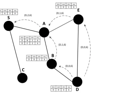
Figure 3-3. Illustration of DSDV operation. The figure shows update messages (destination, distance, sequence number) and routing table entries [destination, next hop, distance, sequence number] related to node D. ... 34
Figure 3-4. Illustration of DSR operation ... 36
Figure 3-5. Illustration of AODV operation ... 37
Figure 3-6. Illustration of DYMO operation ... 38
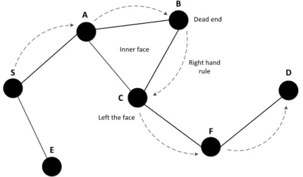
Figure 3-7. Illustration of GPSR operation. Right-hand rule and perimeter routing are employed to overcome dead end problem. ... 39
Figure 3-8. Greedy routing vs. restricted greedy routing in the area of a junction. ... 41
Figure 3-9. Repair strategy: the right-hand rule is used on the level of streets ... 41
Figure 3-10. Forwarding schemes of GeoNetworking ... 45
Figure 3-11. General structure of a DENM ... 46
Figure 3-12. Next-hop predication ... 48
XII List of Figures
Figure 3-14. The distributed gift-wrapping algorithm ... 51
Figure 3-15. The directional sectors of suppression mechanism ... 52
Figure 3-16. Vehicle-Assisted Data Delivery protocol ... 54
Figure 3-17. General structure of a CAM ... 56
Figure 3-18. DCC access state machine ... 58
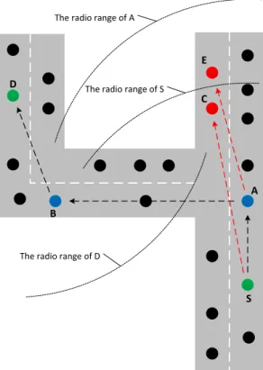
Figure 3-19. Scenarios of RSUs and parked vehicle to connect vehicles that are not in communication range of each other or blocked by building obstacles ... 60
Figure 4-1. The class inheritance of car-following models in SUMO ... 64
Figure 4-2. The architecture of abstract road traffic scenarios... 65
Figure 4-3. ManhattanGrid Scenarios ... 66
Figure 4-4. Spider Scenarios ... 67
Figure 4-5. Man-Made Scenarios ... 68
Figure 4-6. Traffic flows in closed circle traffic simulation ... 69
Figure 4-7. Man-Made network creation ... 69
Figure 4-8. The structure of Man-Made network ... 70
Figure 4-9. Nodes file ... 70
Figure 4-10. Edges file ... 70
Figure 4-11. Type file ... 71
Figure 4-12. Connections file ... 71
Figure 4-13. SUMO road map creation ... 72
Figure 4-14. Road type file ... 72
Figure 4-15. OpenStreetMap and road network of the city center of Clermont-Ferrand ... 73
Figure 4-16. Polygon Creation ... 73
Figure 4-17. Polygon file ... 74
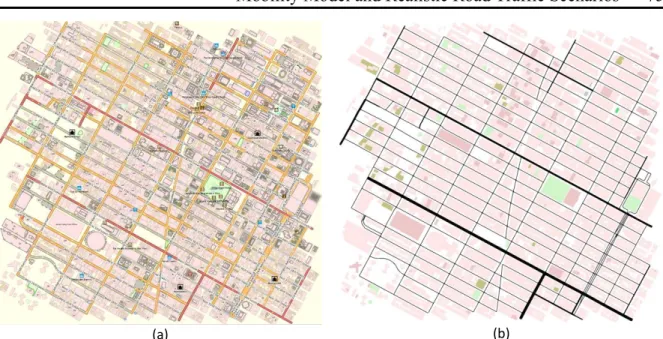
Figure 4-18. OpenStreetMap and SUMO map of the city center of Clermont-Ferrand ... 74
Figure 4-19. OpenStreetMap and SUMO map of Manhattan borough of New York City .. 75
Figure 4-20. OpenStreetMap and SUMO map of A711 Highway of Clermont-Ferrand .... 75
Figure 4-21. Traffic routes in Clermont-Ferrand scenarios ... 76
Figure 4-22. Uniform traffic routes in Manhattan scenarios ... 76
Figure 4-23. Deviated traffic routes in Manhattan scenarios ... 77
Figure 4-24. Illustration of bidirectionally coupled simulation ... 79
Figure 4-25. Sequence chart of association process ... 80
List of Figures XIII Figure 4-27. Sequence chart of information exchanged between OMNeT++ and SUMO . 82
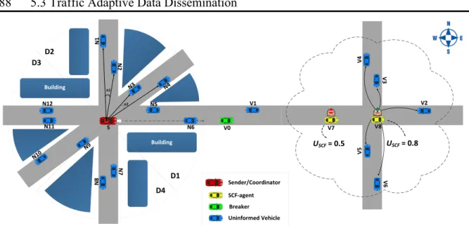
Figure 5-1. Illustration of TrAD protocol. ... 88
Figure 5-2. The operation of TrAD protocol flowchart. ... 89
Figure 5-3. The projection of CBR on the weight and channel status. ... 93
Figure 5-4. The sorting process for priority list. ... 94
Figure 5-5. The identification of Breaker flowchart. ... 95
Figure 5-6. Urban Maps: (a) Manhattan borough in New York City (USA). (b) Clermont-Ferrand (France); Traffic routes are indicated by arrows in urban scenarios; The red start is the source node that periodically broadcasts data messages; The red broken line indicate the boundary of ROI. ... 101
Figure 5-7. Results with a 95% confidence interval in Clermont-Ferrand scenarios: (a) PDR, (b) Number of Transmissions, (c) Delay. ... 102
Figure 5-8. Results with a 95% confidence interval in Manhattan scenarios with the traffic route 1 (uniform): (a) PDR, (b) Number of Transmissions, (c) Delay. ... 102
Figure 5-9. Results with a 95% confidence interval in Manhattan scenarios with the traffic route 2 (deviated): (a) PDR, (b) Number of Transmissions, (c) Delay. ... 102
Figure 5-10. Traffic routes in Manhattan scenarios. (a) Traffic route 1 (uniform). (b) Traffic route 2 (deviated); Traffic routes are indicated by arrows in urban scenarios; The red start is the source node that periodically broadcasts data messages; The red broken line indicate the boundary of ROI. ... 104
Figure 5-11. A711 highway of Clermont-Ferrand, France. ... 107
Figure 5-12. Results with a 95% confidence interval in Highway Scenarios: (a) PDR, (b) Number of Transmissions, (c) Delay. ... 107
Figure 5-13. The impact of GPS drift on TrAD in Manhattan scenarios. ... 109
Figure 5-14. The impact of GPS drift on TrAD in Clermont-Ferrand scenarios. ... 109
Figure 5-15. The data dissemination speed of TrAD, AMD and UV-CAST with perfect GPS. ... 110
Figure 5-16. The data dissemination speed of TrAD, AMD and UV-CAST with 50m GPS drift. ... 110
Figure 5-17. The data dissemination speed of TrAD, AMD and UV-CAST with 100m GPS drift. ... 111
Figure 6-1. The framework of tram simulator ... 115
XIV List of Figures
Figure 6-3. Software of operation console ... 119
Figure 6-4. Hardware of operation console ... 119
Figure 6-5. Force diagram of tram ... 120
Figure 6-6. The measurement data and its fitting line ... 123
Figure 6-7. The structure of brake pedal ... 123
Figure 6-8. Deceleration model with respect to the angle of brake pedal ... 124
Figure 6-9. The relationship between the deceleration and the initial speed in sliding motion ... 127
Figure 6-10. Implementation of traffic scenarios in the tram simulator. (a) OpenStreetMap; (b) Road network; (c) SUMO map. ... 129
Figure 6-11. The flow chart of acceleration ... 130
Figure 6-12. The flow chart of deceleration ... 131
List of Tables XV
List of Tables
Table 2-1. Different generations of cellular networks and respective data rates ... 9
Table 2-2. Access Categories ... 13
Table 2-3. Default EDCA parameter set ... 13
Table 3-1. Different characteristics between MANET and VANET ... 43
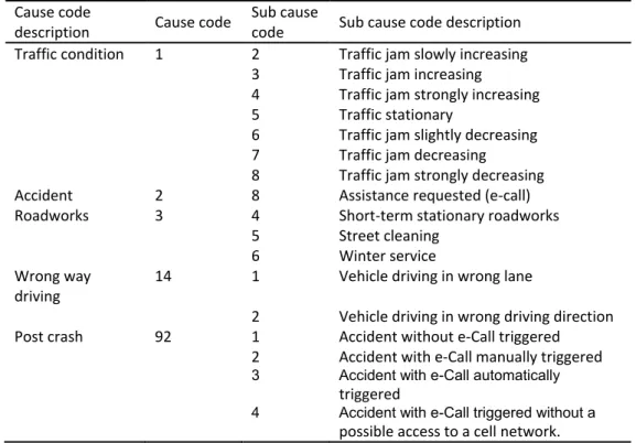
Table 3-2. Selected cause description and cause code assignment for ETSI use case ... 47
Table 3-3. Transmission parameters corresponding to states of ETSI DCC for CCH ... 58
Table 6-4. An overview of simulators and their model libraries ... 77
Table 5-1. Simulation setting ... 99
Table 5-2. Statistics of maps ... 101
Table 6-1. Summary of tram simulators ... 114
Table 6-2. The distance between each tram station of line A ... 116
Table 6-3. Categories of faults ... 120
Table 6-4. The measurement data of acceleration experiment ... 121
Table 6-5. Average acceleration of each experiment ... 121
Table 6-6. The relational expression between the deceleration and the angle of brake pedal of tram “TRANSLOHR STE4” ... 124
XVI Abbreviations
Abbreviations
3GPP: Third Generation Partnership Project 3GPP2: Third Generation Partnership Project 2 AC: Access Category
ACK: Acknowledgment
AIFS: Arbitration Interframe Space
AODV: Ad-hoc On-Demand distance Vector BGP: Border Gateway Protocol
BSM: Basic Safety Message BSS: Basic Service Set CA: Certificate Authority
CAM: Cooperative Awareness Message CCA: Clear Channel Assessment CCH: Control Channel
CDMA: Code-Division Multiple Access CoCar: Cooperative Cars
CoCarX: Cooperative Cars Extended
CSMA/CA: Carrier Sense Multiple Access with Collision Avoidance CTS: Clear to Send
CW: Contention Window
DCC: Decentralized Congestion Control DCF: Distributed Coordination Function
DENM: Decentralized Environment Notification Message DHT: Distributed Harsh Table
DSDV: Destination Sequenced Distance Vector DSR: Dynamic Source Routing
DSRC: Dedicated Short Range Communication DTN: Delay Tolerant Network
DV-CAST: Distributed Vehicular BroadCAST DYMO: Dynamic MANET on demand
DynB: Dynamic Beaconing
Abbreviations XVII EDCA: Enhanced Distributed Channel Access
ETSI: European Telecommunications Standards Institute FCC: Federal Communication Commission (USA) FDMA: Frequency Division Multiple Access FOT: Federal Operational Test
GPRS: General Packet Radio Service GPS: Global Positioning System
GPSR: Greedy Perimeter Stateless Routing
GSM: Global System for Mobility communications GUI: Graphical User Interface
IBSS: Independent Basic Service Set
ICWS: Intersection Collision Warning System IEEE: Institute of Electrical and Electronic Engineers IETF: Internet Engineering Task Force
IFS: Interframe Space
IoT/WoT: Internet of Things / Web of Things IP: Internet Protocol
ITS: Intelligent Transportation System
ITS-G5: Intelligent Transportation System access layer for the 5-GHz band (ETSI) IVC: Inter-Vehicle Communication
LAN: Local Area Network LLC: Logical Link Control LOS: Light of Sight
LTE: Long Term Evolution MAC: Medium Access Control MANET: Mobile Ad-hoc Network MIMO: Multiple Input Multiple Output MNO: Mobile Network Operator MTU: Maximum Transmission Unit OBU: On Board Unit
OCB: Outside the Context of a BSS
OFDM: Orthogonal Frequency Division Multiplexing OLSR: Optimized Link State Routing
XVIII Abbreviations P2P: Peer to Peer
PDR: Packet Delivery Ratio
PeerTIS: Peer-to-peer Traffic Information System PHY: Physical layer
QoS: Quality of Service
QPSK: Quadrature Phase-Shift Keying RF: Radio Frequency
RFC: Request for Comments RIP: Routing Information Protocol ROI: Range of Interest
RREQ: Route Request RREP: Route Reply
RSS: Received Signal Strength RSU: Road Side Unit
RTS: Ready to Send
SAE: Society of Automotive Engineers SCH: Service Channel
SIFS: Short Interframe Space
SOTIS: Self-Organizing Traffic Information System SUMO: Simulation of Urban Mobility
TrAD: Traffic Adaptive Data dissemination protocol TCP: Transmission Control Protocol
TDC: Transmit Data rate Control TDMA: Time Division Multiple Access TIC: Traffic Information Center
TIS: Traffic Information System
TO-GO: Topology-assisted Geo-opportunistic routing TPC: Transmit Power Control
TraCI: Traffic Control Interface (SUMO) TRC: Transmit Rate Control
TTL: Time to Live
TXOP: Transmission Opportunity UDP: User Datagram Protocol
Abbreviations XIX UMB: Urban Multiple Broadcast protocol
UMTS: Universal Mobile Telecommunications System US DOT: US Department of Transportation
UV-CAST: Urban Vehicular BroadCAST V2V: Vehicle to Vehicle
V2I: Vehicle to Infrastructure
V2X: Vehicle to X (pedestrian, bicycle) VANET: Vehicular Ad-hoc Network
Veins: Vehicles in network simulation framework VTL: Virtual Traffic Light
WAVE: Wireless Access in Vehicular Environment
WiMAX: Worldwide interoperability for Microwave access WLAN: Wireless LAN
WME: WAVE Management Entity WSA: WAVE Service Advertisement WSM: WAVE Short Message
WSMP: WAVE Short Message Protocol WSN: Wireless Sensor Network
1
Introduction
Chapter 1
The worldwide economic cost of road crashes and injuries is estimated to be US$ 518 billion per year and the annual congestion cost in France is estimated to be €5.9 billion [1], [2]. The technology of Vehicular Ad hoc Networks (VANETs) is one of the solutions to improve transport activities such as traffic safety, traffic efficiency and even infotainment on wheels, where a great number of event-driven messages need to be disseminated in a timely way in a region of interest (ROI). In comparison with traditional wireless networks, VANETs have to consider the highly dynamic network topology and lossy links due to the mobility of vehicles and the obstacle on the road (buildings or plants). Nowadays, intelligent vehicle becomes a hot topic in automotive industry and scientific community. Many real-world trials are performed by companies or universities, such as Google Car and Tesla Motors. The communication between intelligent vehicles is exactly performed by VANETs. However, there are still some challenges in Inter-Vehicle Communication (IVC) to be solved, such as scalability, reliability, QoS, security and privacy.
First, the density of VANET varies frequently according to events or day time, which requires IVC protocol to well handle the scalability. This requirement is more critical in traffic safety considering the human life. There is another special scenario of VANET because of the huge number of vehicles and the obstacles on the road. For instance, sometimes, a vehicle goes inside of a residence community where there are a few vehicles as so to suffer frequent disconnection. But when it just goes outside of the residence and joins the main road of city, the wireless environment of the vehicle will become tense immediately. For these cases with various scalabilities, IVC protocol should maintain the QoS of application while controlling the congestion of wireless channel. For data dissemination, like warning messages, IVC protocol first should mitigate the broadcast storm problem, and then find a way out to transmit efficiently messages to vehicles in a range of interest, but also handle the transient disconnected network.
Second, the Quality of Service (QoS) is mainly guaranteed by the reliability of IVC. But, the fact is that, the short range communication techniques, e.g., IEEE 802.11p, cannot assure the reliability because of the high mobility of vehicles and the limited communication range. On the other hand, the long range communication techniques, e.g., cellular network (3G/4G), NB-IoT, can provide more reliable connectivity. But they are in need of enough
2 Introduction
basic infrastructures in advance, which would be high cost. Although we can utilize our smartphones in the initial phase of VANETs implementation, there are also some applications, e.g., traffic information system, that need specific communication device with dedicated IVC technique. Moreover, it still does not know that the impact of the overhead from IVC on the current existing cellular network. It is possible to build new infrastructures in the future, especially for the 5G network. Intuitively, the integration of these short and long communication techniques is an optimized solution, i.e., multi-support media access technique. In fact, the European Telecommunication Standard Institute (ETSI) already given the concept for the solution, they design an access layer in the framework of their ETSI ITS protocol stack. The access layer includes communication modules for IEEE 802.11p (ITS-G5) and cellular network. However, how to design the protocol to organize these
communication techniques is a key challenge. The protocol needs to consider respective
mechanisms from upper layer to underlying layer of the Open System Interconnection (OSI) model.
At the same time, security and privacy of IVC are the crucial issues of VANETs, which decide whether IVC applications can be performed or not. With the increasing of the intelligence of automobile, security issue becomes more and more important. IVC protocol also needs to identify the fake data packet in order to avoid the fraud and malicious attacks. Currently, official standards conduct security service at the layer above the application one. For instance, the Wireless Access in Vehicular Environment (WAVE) protocol stack resorts to IEEE 1609.2 to protect the related data messages. Privacy is a sensitive party not only in VANETs but also in other networks, e.g., Internet and cellular network. If the personal information cannot be protected properly, nobody will agree to share their data for others.
Based on the above-mentioned understanding, this thesis will contribute itself to develop IVC protocols for VANETs, especially focusing on data dissemination protocols for ad hoc formation of VANETs. To evaluate the performance of IVC protocols, a dedicated road traffic scenario is required to be modeled, implemented and coupled to the vehicular network simulator. To ensure the solid simulation results, the mobility model of vehicles is also well investigated. Based on this knowledge preparation, an evolved project about tram simulator was performed thanks to the support of local public transportation company, i.e., T2C.
For this thesis, I would like to write in a style that is lively and not overly formal. For instance, some plain words will be used to make clear my understanding and to discuss the
Introduction 3 relationship between some techniques or theories. Sometimes, some question sentences are used to highlight the key issue in the research field. Moreover, there is an overview at the beginning of every chapter, i.e., introduction section, which can give readers a quick look about that chapter.
In the next chapter, i.e., Chapter 2, the contents about IVC protocols in VANETs are presented. That includes basic knowledge, key wireless access technologies, practical applications and crucial research challenges and so on. These contents are not simply put together, but are composed through my serious thinking, understanding and summarizing. For the wireless communication standards as a instance, e.g., IEEE 802.11, ETSI ITS and WAVE, that section can provide most essential contents of the standards that are extracted from the quite lengthy original standards, while being with my own understanding. The open research issues presented in the chapter are also the problems actually met during my research. I attempt to show a global view of the routing protocol research field for VANETs. For Chapter 3, various classical or useful routing classifications are described from primary routing in MANET to up-to-date routing in VANET. The MANET routing is necessary to be mentioned because it is the foundation of VANET routing and several pioneer routing protocols of VANET are inspired from this kind of routing. After that, the useful and potential VANET routing protocols for different communication paradigms are introduced. Meanwhile, some official standards for IVC are also presented. Furthermore, those crucial techniques highlighted are the ones that can actually help IVC according to my works and experience. The Chapter 2 and Chapter 3 present and analyze the basic knowledge, key issues and the key solutions about IVC protocols for VANETs while being with my understanding. Therefore, these parts of my thesis can be a memo book for me, but also can be a quick guide about state-of-the-art of IVC protocols research field for readers.
The main contributions of my thesis are elaborated from Chapter 4 to Chapter 6, especially in Chapter 5. In Chapter 4, the main mobility model of the road traffic simulator used by us is explained. Based on this understanding, various road traffic scenarios are designed and illustrated, e.g., abstract one and realistic one. Then, the realistic traffic scenarios are coupled with network simulator to perform bidirectionally coupled vehicular network simulations. This type of simulation can contribute to carry out an experiment of vehicular networking more close to the real world. Based on the realistic simulation, in Chapter 5, we explore and propose a data dissemination protocol, i.e., TrAD, for ad hoc formation of VANET. This protocol can perform fast information dissemination in a range
4 Introduction
of interest (ROI) in terms of the status of road traffic and network traffic in both urban and highway scenarios. The TrAD protocol contributes itself to develop the advanced algorithm or mechanism for the key techniques to solve the open research issues that are mentioned in Chapter 2 and Chapter 3. By the cooperation between LIMOS and T2C Company, as a main participator, I take part in the project to develop a low-cost tram simulator based on the mobility model of specific type of tram that is used in Clermont-Ferrand, France. In Chapter 6, after presenting the state-of-the-art of current tram simulators, we get inspiration to continue to reduce the cost of current tram simulator. In this thesis, the mobility model of vehicle is the main research object. Therefore, after the introduction of framework design of our tram simulator, the modeling process and the implementation of the mobility model are explained in detail.
Finally, we conclude the thesis and present the perspective for the future work. This thesis not only is the summary of my whole Ph.D. student life, but also the new starting point of my research career.
5
Inter-Vehicle Communication (IVC) in
Chapter 2
Vehicular Ad hoc Networks (VANETs)
2.1
Introduction
Inter-Vehicle Communication (IVC) performs the information exchange among vehicles or between vehicles and available infrastructure by using wireless medium. Those vehicles and infrastructure are connected by wireless communication medium, which form Vehicular Ad hoc Networks (VANETs). One thing needs to make clear, there is another type of vehicular network that is for Intra-Vehicle Communication. It is responsible for the information exchange between sensors or nodes inside of vehicles. However, that is beyond the scope of this thesis. Therefore, notice that, this thesis mainly focuses on the Inter-Vehicle Communication in VANETs, especially on the IVC protocols.
VANETs aim at improving transport activities that include traffic safety, transport efficiency and infotainment on wheels. This chapter is going to give a basic introduction to IVC and VANETs, which provides a necessary knowledge and a theoretical foundation for the following chapters. For more details, first, we will present formations of VANETs and descript the different formations that are with or without infrastructure. Then, various practical and useful wireless medium access technologies and official standards for VANETs are descripted and commented. Based on this, we will present several main applications to prove the application and the functionality of IVC in VANETs. Finally, we uncover that open issues or limitations in VANETs, understanding which can be beneficial to the design of IVC protocols.
2.2
Formations of VANETs
Generally, VANETs are classified into two formations, infrastructure-based and ad hoc, according to whether existing available infrastructure or not, as shown in Figure 2-1 and Figure 2-2. The infrastructure elements mainly include the base station of cellular network (3G/4G), roadside units (RSUs) using WAVE standard or using WiFi or, a few of them, using ZigBee and Bluetooth.
6 2.2 Formations of VANETs
2.2.1
Infrastructure-based Formation
Cloud Vehicular Network 多台 服务器 多台 服务器 多台 服务器 IEEE802.11p Vehicular Network RSU IEEE802.11b/n/g IEEE802.15.4 多台 服务器 多台 服务器 3/4G Cellular SystemFigure 2-1. Infrastructure-based Formation
For using infrastructure, normally, the provider of a service has a long distance with vehicles client. For instance, the distance is beyond the Dedicated Short Range Communication (DSRC) or the line-of-sight (LOS) signal is blocked by buildings or trees. The most popular application of infrastructure-based formation is navigation service by using smartphones or specific GPS devices, e.g., Google Map [3], TomTom [4] and Waze [5]. These applications use cellular network (3G/4G) to connect smartphones or GPS devices on wheels to the background server, by which the information of navigation can be collected to the server to calculate the traffic condition in the real-time. Google Map provides three color lines, i.e., green one, orange one and red one, to represent different levels of traffic conditions, i.e., no traffic delays, medium amount of traffic and traffic delays. The darker the red, the slower the speed of traffic on the road [6]. TomTom provides API for developers to access its real-time traffic information database. Waze organizes a vehicular community, in which every user can post the surrounding traffic information to the community, such as traffic jam, accident, road maintenance, and even the location of the police patrol. However, the number of users using each application is not enough. Consequently, the information collected from users cannot reflect the real traffic situation. The reasons can be seen as follows: First, the multiple choices of navigation applications split the user resource. Moreover, the servers of various applications do not share the data with each other. In addition, some off-line navigation smartphone applications are more and more popular, such as maps.me [7], which can save a great amount of mobile data flow for users.
Inter-Vehicle Communication (IVC) in Vehicular Ad hoc Networks (VANETs) 7 Many projects are performed for evaluating the applicability of using the roadside WiFi or the public WiFi [8]. Given the existence of a great number of Access Points (AP), this internet access technology is very practical and has big potential. There are also some other access approaches, e.g., WAVE and ZigBee, but they are rarely used currently; yet they are the key technologies for the future. If the law confirms that every new car must equip the DSRC device, vehicles can communicate with RSUs by using WAVE stack. There is an interesting idea proposed by Sommer et al. [9]. They discussed the utility of parked cars beside streets to reply the data. These parked cars, like the RSUs, can complement the drawback of short range communications. Moreover, the car parked in a street corner can also help forward the data to pass around buildings. In the future, the smart city will use ZigBee to connect tons of sensors or nodes, in which there must be a great number of road traffic related devices. Therefore, if vehicles can access these devices, a considerable number of services can be developed.
2.2.2
Ad hoc Formation
Vehicular Network
Vehicular Network Vehicular Network
IEEE802.11p
Figure 2-2. Ad hoc Formation
The ad hoc formation of VANETs, as shown in Figure 2-2, mainly is used for safety applications and the platooning. By using IEEE 802.11p, vehicles could cooperate together and be aware of each other in the one-hop neighborhood, so the emergency event can be informed to very vehicle involved in advance, such as intersection assistance systems, abnormal driving warming and Electronic Emergency Break (EEB). The biggest advantage of this formation is the real-time service. Frequent data exchange, e.g., 10 Hz, can be supported by the capacity of IEEE 802.11p. The default data rate is 6 Mbit/s for broadcasting which provides a reasonable balance between the signal robustness and the service requirement. However, the channel would be overloaded due to the dense network and the high transmit frequency. Therefore, the Decentralized Congestion Control (DCC)
8 2.3 Wireless Medium Access Technologies and Standards
standard has been proposed by European Telecommunications Standards Institute (ETSI) [10] [11]. There are also other congestion control protocols proposed by researchers, e.g., PULSAR [12], LIMERIC [13] and DynB [14]. These efficient and well-known protocols adjust the transmit rate of beaconing to maintain a reasonable Channel Busy Ratio (CBR). Another application is worth mentioning, i.e., the platooning or the road train. This service can organize a group of vehicles by using ad hoc formation of VANET to travel smoothly and efficiently on the highway, by which the transport is optimized and the fuel consumption is reduced.
2.3
Wireless Medium Access Technologies and
Standards
A suitable wireless medium access technology can significantly improve the performance of applications. Various access technologies and related standards will be discussed in this section. For VANETs, there are two main types of access technologies, i.e., long range communication technologies and short range communication technologies. The former mainly refers to cellular networks and the latter mainly includes WiFi and IEEE 802.11p. Here, we do not want to describe every specific technique in detail, but we will discuss which access technology is, or is not, suitable to what application, and give some conclusions according to the previous research projects. Therefore, we can get a general understanding to each access technology. After that, two ITS protocol stacks, i.e., WAVE and ETSI ITS, are introduced, which are used in the USA and Europe, respectively. At last, a new potential access technology, i.e., NB-IoT, will be presented for the future low cost, low energy consumption long range communication.
2.3.1
Cellular Network
There are three major standardization bodies govern the specification of cellular networks, which include 3GPP (Third Generation Partnership Project), 3GPP2 (Third Generation Partnership Project 2) and IEEE (Institute of Electrical and Electronics Engineer). The standards proposed by 3GPP are GSM, UMTS and LTE. The 3GPP2 family of standards includes CDMAone, CDMA2000 and UMB. The UMB has been abandoned in favor of LTE. IEEE proposed WiMAX standard for the long range communication in urban scenarios, but, for various reasons, the work group of WiMAX has joined the one of LTE.
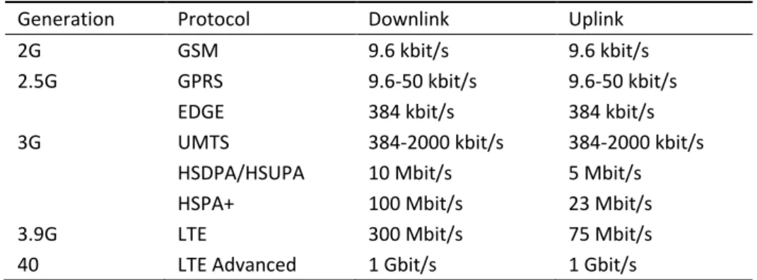
Inter-Vehicle Communication (IVC) in Vehicular Ad hoc Networks (VANETs) 9 The different generations of cellular networks and respective data rates is shown in Table 2-1.
Table 2-1. Different generations of cellular networks and respective data rates
Generation Protocol Downlink Uplink 2G GSM 9.6 kbit/s 9.6 kbit/s 2.5G GPRS 9.6-50 kbit/s 9.6-50 kbit/s
EDGE 384 kbit/s 384 kbit/s 3G UMTS 384-2000 kbit/s 384-2000 kbit/s
HSDPA/HSUPA 10 Mbit/s 5 Mbit/s HSPA+ 100 Mbit/s 23 Mbit/s 3.9G LTE 300 Mbit/s 75 Mbit/s 40 LTE Advanced 1 Gbit/s 1 Gbit/s
Although the standards of cellular networks are different, the basic idea is always the same. For cellular networks, the world is divided into different cells. Each cell is served by a base station. A cellphone, properly in a mobile vehicle, connect to the base station serving the cell where the cellphone is located in. Moreover, the cellphone will switch to an appropriate base station when it crosses the boundary of cells. The illustration of cellular network is shown in Figure 2-3.
f1 f0 f2 f2 f0 f1 f2 f2 f0 f1 f2 f1 f0 f2 f1 f0 f2 f2 f0 f1 f2
Figure 2-3. Cellular Network
In the last decade, several projects and Field Operational Tests (FOTs) have been performed, from which we can get some useful and inspired information for the implement of cellular networks in VANETs. First of all, the feasibility of cellular networks is proved
10 2.3 Wireless Medium Access Technologies and Standards
by FOTs, which shows that the vehicle at a very high speed, i.e., 290 km/h, can connect to the base station of the cellular network. The signal is only interrupted after a sudden braking behavior for the handover prediction fails. In 2006, CoCar (Cooperative Car) project started to investigate the feasibility of using cellular networks solely for VANETs [15]. The results showed that cellular networks achieve a very good scalability for Traffic Information Systems (TISs). However, the technology is not able to support safety-critical applications, since the delay is on the order of seconds. Following this project, in 2009, CoCarX (Cooperative Car Extended) integrated IEEE 802.11p into the cellular communication system [16]. At that time, an early version of LTE was used in CoCarX project. Therefore, CoCarX builds a completely heterogeneous vehicular network, in which vehicles can exchange messages by IEEE 802.11p in the one-hop neighborhood and send these messages to vehicles or infrastructure far away by LTE. The report showed that the system not only supports the TIS, but also can satisfy some safety applications, e.g., hazard driving warning. The only limitation is the capability of the system. It is still not known whether cellular networks scale well with the increasing number of participating vehicles. However, considering the well implemented infrastructure of cellular networks, this access technology is the most suitable access technology for the early phase of IVC applications since the penetration rate of DSRC devices is still very low.
2.3.2
WiFi
DIFS DIFS
SIFS Busy Medium
Contention Window
Backoff Slots Next Frame
Defer Access
Slot time
Select Slot and Decrement Backoff as long as medium is idle
Immediate access when Medium is free >=DIFS
Figure 2-4. The access procedure of the MAC layer of IEEE 802.11
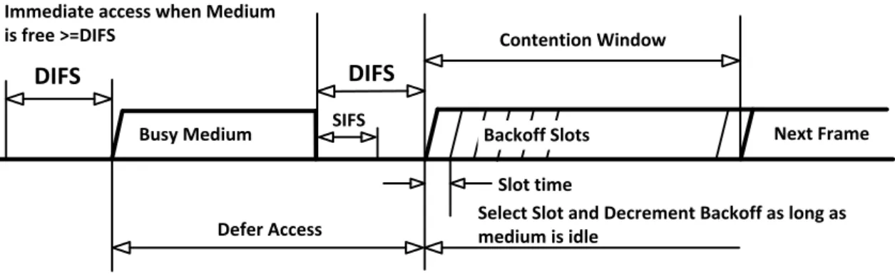
WiFi is an access technology based on IEEE 802.11 that allows communication devices to connect each other in Wireless Local Area Network (WLAN), mainly using 2.4G Hz band. Generously, WiFi and WLAN could be believed to be a synonym, since most WLANs are composed by using IEEE 802.11. In addition, for completeness, WLAN is also the name of IEEE working group of 802.11.
Inter-Vehicle Communication (IVC) in Vehicular Ad hoc Networks (VANETs) 11 The fundamental access method of the MAC layer of IEEE 802.11 is the Distributed Coordination Function (DCF) known as Carrier Sense Multiple Access with Collision Avoidance (CSMA/CA), as shown in Figure 2-4 [17]. When stations prepare to transmit frames, they should determine that whether the channel is idle or not in Physical Layer Convergence Protocol (PLCP) sublayer. This function is implemented by Clear Channel Assessment (CCA). The station can transmit a frame only if the channel is clear or idle for at least one DIFS (DCF InterFrame Space). DIFS is calculated by Equation (2-1).
(2-1)
If a station wants to transmit a frame, it must sense the channel (busy or clear) by performing CCA. If the channel is busy, the station will queue the frame and start to contend the channel by using a backoff procedure. It selects a random backoff time (delay) from the pre-configured Contention Window (CW). A timer is triggered to decrement the backoff time if the channel is idle. Before the timer expiring, if the channel turns to be busy again, the timer will be frozen until the channel turns to idle again for at least one DIFS. This backoff procedure also happens after a successful transmission to give other stations a chance to access the channel. To mitigate hidden terminal problems, the MAC layer provides the Ready-To-Send (RTS) and Clear-To-Send (CTS) mechanism.
The Basic Service Set (BSS) is a central concept of IEEE 802.11, in which synchronized stations in the same BSS can communicate with each other. There are two modes of BSS, i.e., infrastructure and ad-hoc. In infrastructure mode, stations connect to the Access Point (AP) and then associate to send or receive data. In the other hand, stations in the ad-hoc mode form an Independent Basic Service Set (IBSS) and then communicate with each other directly.
The utility of WiFi for Intelligent Transportation System (ITS) has been investigated by the early measurement campaigns. The “drive-thru Internet” project investigated the impact of the speed of vehicles on the capability to connect to AP and exchange data [8]. The results showed that the infrastructure mode of WiFi is not suitable to high dynamic and time-sensitive applications of ITS. The reason lies in the long time association process of stations with APs. Moreover, due to the limited communication range, this association process will be happened frequently when vehicle switches connection from one AP to the other.
12 2.3 Wireless Medium Access Technologies and Standards
2.3.3
IEEE 802.11p
Given the drawback of WiFi mentioned in the last section, a new communication technology needs to be developed for ITS. Therefore, in 1999, US Federal Communication Commission (FCC) allocated 75 MHz of dedicated bandwidth in the 5.9 GHz region for ITS applications. Seven 10 MHz channels are provided to serve the communication on the road. These channels are given the specific number ID, as shown in Figure 2-5a, that is, channels 172, 174, 176, 178, 180, 182, 184. Channel 178 is used to transmit and receive control messages, namely Control Channel (CCH). Channels 172 and 184 are reserved for the public safety applications. These dedicated frequency band is called Dedicated Short Range Communication (DSRC) band. In 2008, European Commission and Electronic Communications Committee (ECC) also allocated five channels for ITS, i.e., 172, 174, 176, 178, 180, as shown in Figure 2-5b. To enable the efficient use of the DSRC band, US Department Of Transportation (DOT) developed the standard IEEE 802.11p since 1997 [18]. Currently, the IEEE 802.11p has been integrated into the 2012 version of IEEE 802.11.
174 - SCH 172 - SCH 5.860 5.870 5.880 5.890 5.900 5.910 5.920 f (GHz) 176 - SCH 178 - CCH 180 - SCH 182 - SCH 184 - SCH Safety Safety (a) 174 - SCH 172 - SCH 5.860 5.870 5.880 5.890 5.900 5.910 5.920 f (GHz) 176 - SCH 178 - SCH 180 - CCH 182 184 Future ITS Safety Non-safety (b)
Figure 2-5. Channel Allocation of WAVE (a) and of ETSI ITS (b)
Based on extensive research, testing and feasibility studies, IEEE 802.11p adopted the PHY layer of IEEE 802.11a and the MAC layer of IEEE 802.11e. The necessary amendments were made for the requirement of ITS applications. 10 MHz bandwidth is expected by ITS instead of 20 MHz of the original PHY layer of IEEE 802.11a. Therefore, all symbol times and CCA time are doubled so that the original data rate is cut into half, i.e., 3 Mbit/s, 4.5 Mbit/s, 6 Mbit/s, 9 Mbit/s, 12 Mbit/s, 18 Mbit/s, 24 Mbit/s, 27 Mbit/s. The bright side of this amendment is to significantly decrease the inter-symbol interference, which can make transmissions more robust. For the MAC layer, a new operation mode, i.e., OCB (outside the context of a BSS), is introduced to allow stations to be not necessary to
Inter-Vehicle Communication (IVC) in Vehicular Ad hoc Networks (VANETs) 13 establish a BSS and also do not perform the authentication, association and data confidentiality service of the IEEE 802.11. The BSS identifier of all frames is set to a wildcard value, which allows all recipients to process the frame. These amendments significantly reduce the transmission delay. In addition, the broadcast and the multicast of IEEE 802.11p do not have the acknowledgment process, the RTS/CTS mechanism and the MAC-level recovery mechanism. As a result, the transmission delay continues to be reduced, but the reliability of transmissions cannot be guaranteed.
IEEE 802.11p uses Enhanced Distributed Channel Access (EDCA) mechanism to perform the channel access procedure. Frames are classified into four Access Categories (ACs), as shown in Table 2-2, providing different priorities for the data from higher layer. That is, the data with a higher priority will be transmitted first.
Table 2-2. Access Categories
AC Description AC_BE Best effort AC_BK Background AC_VI Video AC_VO Voice
In EDCA of IEEE 802.11p, the Interframe Space (IFS) uses a new concept, namely using Arbitration Interframe Space (AIFS) instead of DIFS in WiFi. The AIFS length and the maximum and minimum Content Window (CW) are based on the priority (category) of the data, as shown in Table 2-3. aCWmin and aCWmax are equal to 15 and 1023, respectively.
Table 2-3. Default EDCA parameter set
AC AIFSN CWmin CWmax AC_BE 9 aCWmin aCWmax AC_BK 6 aCWmin aCWmax AC_VI 3 (aCWmin+1)/2-1 aCWmin AC_VO 2 (aCWmin+1)/4-1 (aCWmin+1)/2-1
Here, we will show the access procedure of IEEE 802.11p by using EDCA, as shown in Figure 2-6, including the calculation of AIFS[AC] and the backoff time for different access categories (ACs).
14 2.3 Wireless Medium Access Technologies and Standards
AIFS DIFS
SIFS Busy Medium
Contention Window
Backoff Slots Next Frame
Defer Access
Slot time
Select Slot and Decrement Backoff as long as medium is idle
Immediate access when Medium is free >= AIFS[AC]
AIFS[AC] AIFS[AC]
Figure 2-6. The access procedure of MAC layer of IEEE 802.11p
When the MAC layer receives a data from upper layer, the data is stored into respective AC queue according to its priority (AC). EDCA will calculate a AIFS[AC] according to the data’s AC by using Equation (2-2).
[ ] [ ] (2-2)
AIFSN[AC] can be obtained in Table 2-3. aSlotTime and aSIFSTime are equal to 13 µs and 32 µs, respectively.
Before transmitting the data, the station determines the status of the channel at first. If the channel is free for greater than or equal to AIFS[AC], the data will be sent. If the channel is busy when the station wants to transmit the data, exclusive of the AIFS[AC] period, a backoff procedure will be attached. The core operation of the backoff procedure is to obtain a random integer value CW[AC] that represents the content window. The value of CW[AC] is between CWmin and CWmax.
[ ] (2-3)
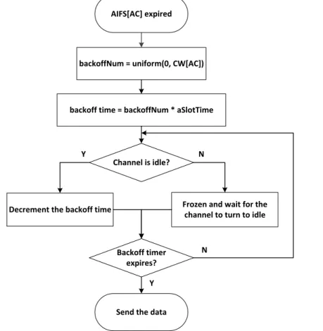
CW[AC] can be obtained according to the different events that invoke the backoff procedure. For a clear explanation, a flow chart of the backoff procedure in EDCA is shown in Figure 2-7.
Inter-Vehicle Communication (IVC) in Vehicular Ad hoc Networks (VANETs) 15 AIFS[AC] expired
Channel is idle?
Frozen and wait for the channel to turn to idle
Y
N backoffNum = uniform(0, CW[AC])
backoff time = backoffNum * aSlotTime
Decrement the backoff time
Backoff timer expires?
N
Send the data Y
Figure 2-7. The flow chart of the backoff procedure in EDCA
A backoff number, i.e., backoffNum, is selected between 0 and CW[AC] following uniform distribution. The backoff time can be obtained by multiplying backoffNum and a slot time, i.e., aSlotTime. Then, the station checks the status of the channel. If the channel is idle, the backoff time will be decremented. Otherwise, the backoff time will be frozen, waiting for the channel to turn to be idle. Once the backoff timer expires, the data will be sent.
2.3.4
WAVE
The USA adopts IEEE 802.11p as the lower layer of its ITS protocol stack that is called Wireless Access in Vehicular Environment (WAVE) protocol stack, as shown in Figure 2-8. This stack also includes IEEE 1609 standard suite, e.g., IEEE 1609.4 for multi-channel operation, IEEE 1609.3 for networking service and IEEE 1609.2 for security service [19].
16 2.3 Wireless Medium Access Technologies and Standards UDP / TCP / other IPv6 Man ag eme n t Se cu rity WSMP LLC WAVE MAC
and Channel Coordination
PHY 1609.2 16 09 .3 16 09.4 80 2. 11 p
Figure 2-8. Architecture of WAVE
WAVE device is defined to be equipped with one single radio and can communicate on seven channels in 10 MHz DSRC band. In order to synchronize all vehicles on the same channel, IEEE 1609.4 is developed to manage the multiple channels [20]. Since IEEE 1609.4 is an additional MAC layer on the top of IEEE 802.11p, it is also called WAVE MAC. The channel is classified into two parts, i.e., Control Channel (CCH) and Service Channel (SCH). In default “continuous option” of IEEE 1609.4, every part of channel occupies 50 ms and switches between each other. To mitigate the synchronization errors, the first 4ms of each 50 ms time interval is left to be a guard interval. However, a number of transmissions would be triggered at the border of the switch channels, these packets will be suspended until the next time interval of the same channel. As a result, many contentions blow up at the beginning of the time interval so that a large amount of collisions would occur [21].
To notify neighbors the type of services offered on the next SCH, the WAVE station broadcast WAVE Service Advertisements (WSA) on the CCH. This functionality is supported by IEEE 1609.3 [22]. This standard also provides networking services for the legacy IPv6 and a lightweight WAVE Short Message Protocol (WSMP). The IPv6 is mainly used to communicate with the RSUs or future IoT/WoT devices for the non-safety application. The WSMP is responsible for exchanging WAVE Short Messages (WSM) between WAVE stations for the safety application. Moreover, IEEE 1609.2 specifies communications security for WSA and WSM [23].
Inter-Vehicle Communication (IVC) in Vehicular Ad hoc Networks (VANETs) 17
2.3.5
ETSI ITS
ETSI ITS protocol stack is standardized by ETSI in Europe. The access technology of this stack is also based on IEEE 802.11p, operating 5 GHz frequency band for ITS. Therefore, the access technology is called ITS-G5. However, the ETSI ITS device and stack are different from the ones of WAVE. ETSI ITS device is defined to be multi-radio and multi-channel mode. That means the station should use an exclusive ITS-G5 radio to exchange safety messages on Control Channel, i.e., G5-CCH, and another ITS-G5 radio is responsible for transmitting service messages on Service Channel, i.e., G5-SCH. This mode effectively reduces the synchronized collisions. The architecture of ETSI ITS is shown in Figure 2-9.
Safety Efficiency Comfort ...
Man ag eme n t Se cu rity Applications Facilities
Transport and Network
Access CAM DENM LDM ... Application Information BTP ITS-G5 (G5-CCH) ITS-G5 (G5-SCH) WiFi 3G GeoNetworking TCP/UDP IPv6
Figure 2-9. Architecture of ETSI ITS
The facilities layer provides several functional messages and information resource, such as Cooperative Awareness Messages (CAMs), Decentralized Environment Notification Messages (DENMs) and the Local Dynamic Map (LDM) [24]. LDM is a database that store information about local neighborhood. The transport and network layer not only supports the TCP/UDP over the IPv6 networking service but also the Basic Transport Protocol (BTP) over the GeoNetworking service. As the WAVE stack, the IPv6 networking service is mainly to communicate with RSUs or the future IoT/WoT devices for non-safety applications, while the GeoNetworking service is responsible for exchange messages between vehicles for safety applications. Especially, ETSI propose a concept of access layer
18 2.3 Wireless Medium Access Technologies and Standards
that adopts WiFi and cellular network along with ITS-G5. ETSI ITS stack intends to abstract the different access technologies and give an identical medium access layer.
2.3.6
NB-IoT
In recent two years, NB-IoT (Narrowband Internet of Things) is invested by many manufactures, such as Huawei, Vodafone, Intel and Nokia, since its unique features and technical feasibility. NB-IoT is a Low Power Wide Area (LPWA) wireless access technology operates in licensed or shared spectrum. Especially, it is able to be deployed over existing mobile network, e.g., LTE. Its characteristics include full coverage, low device and deployment cost, long battery life and supporting for a massive number of IoT devices and so on. 3GPP has adopted NB-IoT feature to specify a new access technology for cellular IoT while was making a full standardization for it. The first commercial trial of pre-standard NB-IoT was completed in November 2015. Huawei and Vodafone have successfully integrated the technology into the operator’s existing mobile network in Spain, in which the first NB-IoT message sent to an IoT device. The NB LTE-M, one of cellular IoT access technologies supported by 3GPP, not only can operate in a 200 kHz band refarmed from GSM but also can be able to operate in shared spectrum with an existing LTE network. Therefore, it is recommended by Nokia. The NB LTE-M Rel. 13 version can achieve about 15 km communication range with 150 kbps data rate.
Given the features of NB-IoT, this access technology can bring a great improvement for long range communication, delay tolerant and low data rate IVC applications, such as traffic information system, smart parking, fleet management. NB-IoT will be an important complement to cellular networks for low data rate IVC applications. Since it is still unknown whether cellular networks can scale well with the increasing of participating vehicles, NB-IoT can effectively mitigate the stress of network load for cellular networks. A unique advantage of NB-IoT is that, by using this access technology, a massive number of IoT devices can be connected to vehicles in a long communication range. For the short range communication, WAVE and ETSI ITS stacks have defined respective transport and network layer for IPv6 to connect to IoT devices. We believe that NB-IoT would be a new choice for the long range communication. According the report of Machina Research, the applications about connected car and fleet will take 20% market share in the future cellular IoT connections (Machina Research, May 2015).
Inter-Vehicle Communication (IVC) in Vehicular Ad hoc Networks (VANETs) 19
2.4
Applications
After discussing the formation, access technologies and standards for VANETs, the IVC applications will be elaborated in this section, aiming to demonstrate the functionality of IVC applications. This thesis will give comments carefully on which technology gains the practical value for current applications, which one can be feasible and potential in the future. Considering different applications use different communication principles, we select three applications that represent the main functionality of IVC, i.e., traffic information systems for non-safety, intersection collision warning system for safety and platooning for transport efficiency.
2.4.1
Traffic Information Systems (TISs)
Navigation service is widely used by drivers through navigation devices, e.g., TomTom and Navigon, or Smartphone APP (application), e.g., Google Map, TomTom and Waze. Those devices utilize the GPS signal and the local installed map to locate vehicles position and calculate the route to the destination. However, the navigation that simply considers the distance from the source and the destination is not satisfied the current requirement of intelligent transport. The future navigation not only can provide the traditional navigation service, but also can provide real-time traffic information about the interested area. This non-safety application system is called Traffic Information System (TIS).
In fact, the first attempt has already been implemented by Google Map, TomTom and Navigon. They use the current navigation information of users to deduce the actual traffic density on the road. But, as mentioned in section 1.1.1, the source data from their users falls far short of the adequate information that can calculate the accurate real-time traffic information, because the number of users for every service is not enough. Moreover, those services have their own servers that cannot share the information between each other. Even so, these commercial implements still proved the possibility and the applicability of the centralized TIS, in which the system aggregates (uplink) the traffic information from infrastructure and vehicles, processes and manages the data, and then disseminates (downlink) to vehicles in the region of interest (ROI). On the other hand, there is an alternative system that resorts to fully distributed data storage in every vehicle rather than in the central server. We will describe the two kinds of TIS system in detail in the following sections.