Design of a Fast Cycle Time Hot Micro-Embossing Machine By
Matthew E. Dirckx
B.S., Mechanical Engineering University of Oklahoma, 2003
Submitted to the Department of Mechanical Engineering in Partial Fulfillment of the Requirements for the Degree of
Master of Science in Mechanical Engineering at the
Massachusetts Institute of Technology June 2005
D Massachusetts Institute of Technology All Rights Reserved
MASSACHUSETTS INS E
OF TECHNOLOGy
JUN
16
2005
LIBRARIES
Signature of Author ... ...
Department of Mechanical Engineering May 6, 2005
C ertified by
...
.
. . . . .David E. Hardt Professor of Mechanical Engineering Thesis Supervisor
Acceptedby... ...
Lallit Anand Chairman, Department Committee on Graduate Students
Design of a Fast Cycle Time Hot Micro-Embossing Machine by
Matthew E. Dirckx
Submitted to the Department of Mechanical Engineering on May 6, 2005 in Partial Fulfillment of the Requirements for the Degree of
Master of Science in Mechanical Engineering ABSTRACT
In the coming years, there will be a huge market for mass-produced polymer micro-devices. These devices include microfluidic "labs on a chip," micro-optical chips, and many others. Several techniques exist for producing micron-scale features in polymer materials. One of the most promising of these techniques is Hot Micro-Embossing (HME). In this process, a thermoplastic polymer workpiece is heated above its glass transition temperature and a micro-patterned die is forced into it. The polymer conforms to the workpiece and the features are replicated. Much of the research to date concerning HME has not addressed fundamental issues that will be central to successful mass
production using this process. There is a compelling need to study HME from the perspective of manufacturing process control. In order to conduct such a program, a HME machine is needed that allows the operator to precisely control all the potentially significant process parameters. No existing machine fully meets this requirement. This thesis concerns the conceptual and detailed design of a HME system, including the platen
assembly and the temperature control system. A parametric model and finite element analysis were used to guide the design of the platen assembly and to assess its thermal and structural performance. A dynamic thermal model of the temperature control system was developed. This model was used to guide the selection of components and to predict the performance of the system as a whole. The new design will have a short cycle time, will permit the use of full wafer-size embossing tools, and will be able to follow a user-programmed trajectory in displacement, force, and temperature.
Thesis supervisor: David E. Hardt
Acknowledgements
First, I wish to thank my parents for their love and guidance. With their unending support and encouragement, and by their example, I have gone far.
I would like to thank my advisor, Prof. Dave Hardt, for the opportunity to join his lab, and for his mentorship during my work.
I would also like to thank my colleagues. Grant Shoji and Kunal Thaker directly contributed to this work by their research into heat transfer fluids, control valves, vacuum pumps, and hot oil pumps, by their work to select and procure these and many other components of the fluid system, and by their analysis of the system pressure drop. Without their assistance in these and many other areas, the design of the new machine would have been a much greater burden. Adam Rzepniewski and Wang Qi have also contributed their advice, and Catharine Nichols has been swamped with paperwork for this project. All of my colleagues have made the lab a friendly and fun place to work.
I would also like to thank the staff of the LMP machine shop, especially Gerry Wentworth, for all of their instruction and help with machining the components for the new machine.
Tricia has given me her love and support, and has endured the crowds and climate of Boston, and for this, I will always be grateful.
Finally, I would like to thank the Singapore-MIT alliance for funding this work and making my studies at MIT possible.
Table of contents
A cknow ledgem ents... 3
Table of contents... 4
List of figures... 7
N om enclature ... 9
1 Introduction... 11
1.1 G oing "M icro" ... 11
1.2 M anufacturing at the m icron scale... 12
1.3 Overview of thesis ... 13
2 Background ... 14
2.1 Techniques for m icron-scale polym er replication ... 14
2.1.1 Soft lithography ... 14
2.1.2 M icro-injection m olding ... 15
2.1.3 U ltraviolet em bossing ... 16
2.1.4 H ot m icro-em bossing... 17
2.2 Prior work in HME manufacturing process control... 19
2.3 The m anufacturing process control paradigm ... 21
2.4 Existing H M E m achines ... 22
2.4.1 The generation 1 H M E m achine ... 23
2.4.2 Com m ercially available H M E m achines ... 26
2.5 The need for a new HM E m achine ... 28
3 G oals for the new m achine ... 30
3.1 Introduction... 30
3.2 Probing spatial variation ... 30
3.3 W orkpiece m aterial and therm al requirem ents ... 32
3.4 Tim e-dom ain process param eters ... 32
3.5 A utom ation ... 38
3.6 W orkpiece and tool fixturing ... 39
3.7 Project scope ... 40
3.8 Summary of goals for the generation 2 HME machine ... 41
4 Concept developm ent and evaluation ... 43
4.1 Introduction... 43
4.2 Tem perature control... 43
4.2.1 Therm oelectric (Peltier)... 44
4.2.2 M ixed electric & fluid... 45
4.2.3 A ll fluid... 47
4.3 Concepts for therm al fluid supply system ... 47
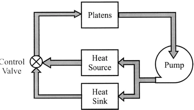
4.3.1 Bulk heating & cooling... 48
4.3.2 Separated stream s... 48
4.4 Selection of w orking fluid ... 51
4.5 W orkpiece and tool fixturing ... 52
4.6 Sum m ary of conceptual design... 53
5 D esign of the platen assem bly ... 55
5.2 D esign of the platens... 56
5.2.1 Param etric m odel of platen perform ance... 57
5.2.2 Manufacturability & selection of tube diameter ... 64
5.2.3 Specifying a flow rate ... 65
5.2.4 Final platen design ... 71
5.3 Fixturing and m ounting... 71
5.3.1 M ounting the platens... 72
5.3.2 W orkpiece clam p ... 74
5.3.3 Tool chuck (vacuum )... 75
5.3.4 Spacer plate... 77
5.4 Structural and Thermal finite element model of platen assembly ... 78
5.4.1 Structural... 78
5.4.2 Therm al... 81
5.5 M anifolds ... 87
5.6 Insulation... 94
5.7 Sum m ary of platen assem bly design... 95
6 D esign of the tem perature control system ... 100
6.1 Introduction... 100
6.2 Selection of oil/w ater heat exchanger ... 101
6.3 D ynam ic therm al m odel... 104
6.3.1 Platen m odel... 105
6.3.2 H eater m odel... 107
6.3.3 Oil/w ater heat exchanger m odel ... 108
6.3.4 Control valve m odel... 108
6.4 Selection of electric circulation heater... 109
6.5 Predicted dynam ic therm al perform ance ... 112
6.6 M odeling fluid losses... 119
6.6.1 Selection of control valves... 120
6.6.2 Selection of pum p & m otor... 122
6.7 Sizing of the Expansion Tank ... 124
6.8 Safety equipm ent ... 126
6.9 Summary of Temperature control system design ... 127
7 Conclusions and future w ork ... 128
7.1 Sum m ary... 128
7.1.1 The final design... 128
7.1.2 Predicted system perform ance ... 129
7.2 Conclusion ... 129 7.3 Future w ork... 130 Appendix... 132 A M aterial properties ... 133 A .1 Properties of Paratherm M R ... 133 A .2 Properties of PM M A ... 135 A .3 Properties of Copper ... 138 A .4 Properties of Silicon... 139
A .5 Properties of Therm agon T-Pli 220 ... 141
B Com ponent drawings ... 144 B.1 Platen... 144 B.2 Spacer... 145 B.3 Clam p... 146 B.4 V acuum chuck ... 147 B.5 M anifold... 148
B.6 Bottom carrier plate ... 149
B.7 Top Carrier... 150
B.8 Screw block... 150
B.9 T-slotted table ... 151
B.10 Platen assem bly... 152
B. 11 Oil-W ater heat exchanger ... 153
B.12 H eater... 154
C M atLab code ... 156
C.1 Properties of Paratherm M R ... 156
C.2 Param etric m odel of internal convection for platens ... 156
C.3 Dynam ic therm al m odel... 157
C.3.1 M ain program ... 157
C.3.2 Cold heat exchanger m odule... 159
C.3.3 Electric heater m odule ... 159
C.3.4 Platens ... 160
C.3.5 Calculate branch flows... 161
List of figures
Figure 2-1 Schematic for Soft Lithography... 15
Figure 2-2 Schematic for micro-injection molding ... 16
Figure 2-3 Schematic for UV embossing... 17
Figure 2-4 Schematic for hot micro-embossing... 18
Figure 2-5 Temperature and force trajectory in HME ... 19
Figure 2-6 Generic manufacturing process model... 21
Figure 2-7 Generation 1 machine overview... 24
Figure 2-8 Generation 1 machine platens ... 25
Figure 2-9 Table of commercial hot embossing machines ... 27
Figure 2-10 EV Group 520HE... 27
Figure 2-11 Obducat NIL-4 ... 27
Figure 2-12 Jenoptik HEXOI... 28
Figure 2-13 Suss SB 6e... 28
Figure 3-1 Thermal model of workpiece ... 34
Figure 3-2 Simplified thermal model of workpiece with boundary conditions... 34
Figure 4-1 Bulk heating & cooling of fluid ... 48
Figure 4-2 Separated hot & cold streams... 49
Figure 4-3 Photo of an electric circulation heater []... 50
Figure 4-4 Diagram of plate and frame heat exchanger []... 51
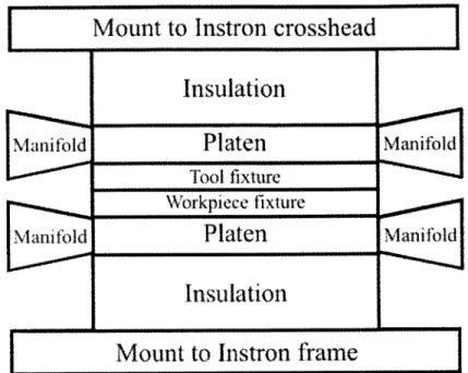
Figure 5-1 Basic schematic of platen assembly... 56
Figure 5-2 Minimal platen design... 57
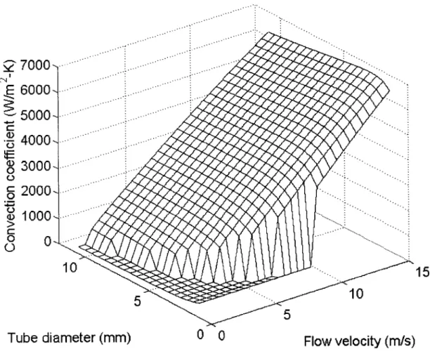
Figure 5-3 Convection coefficient results from parametric model... 60
Figure 5-4 Dependence of platen mass on tube diameter ... 61
Figure 5-5 Pressure drop from parametric model... 62
Figure 5-6 Volume flow rate from parametric model... 63
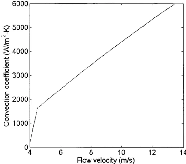
Figure 5-7 Convection coefficient vs. flow velocity ... 66
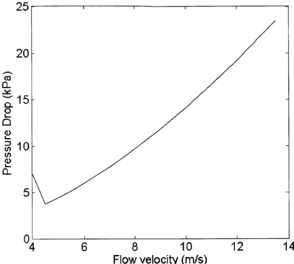
Figure 5-8 Pressure drop vs. flow velocity ... 67
Figure 5-9 Biot number vs. flow velocity... 68
Figure 5-10 Time constant vs. flow velocity ... 70
Figure 5-11 Final platen design ... 71
Figure 5-12 T-slotted table... 73
Figure 5-13 B ottom carrier plate... 73
Figure 5-14 Top carrier plate mounted to anvil... 74
Figure 5-15 Workpiece clam plate... 75
Figure 5-16 Vacuum chuck... 76
Figure 5-17 Detail of vacuum port... 77
Figure 5-18 The spacer plate... 78
Figure 5-19 Detail of structural FEA model of platen... 79
Figure 5-20 von Mises stress in platen (Pa)... 80
Figure 5-21 Vertical deflection at top of platen... 81
Figure 5-22 Platen stack model... 82
Figure 5-23 Temperature in center of PMMA ... 82
Figure 5-25 Edge effect over time ... 85
Figure 5-26 Fluid temperature change along a tube ... 87
Figure 5-27 Flotran CFD model of manifold design ... 88
Figure 5-28 Mean flow velocity in each tube in the CFD model ... 89
Figure 5-29 Convection coefficient in each tube... 90
Figure 5-30 Manifold design ... 91
Figure 5-31 Stress distribution in the manifold ... 92
Figure 5-32 Thermal stress model ... 93
Figure 5-33 Exploded view of platen stack ... 96
Figure 5-34 The full platen assembly ... 97
Figure 5-35 Three-dimensional view of the full platen assembly ... 98
Figure 5-36 Table of thermal masses (*=estimated property)... 99
Figure 6-1 System A rchitecture ... 101
Figure 6-2 Mixing hot and cold fluid to produce desired temperature ... 102
Figure 6-3 Photo of oil cooler... 103
Figure 6-4 Oil cooler performance ... 103
Figure 6-5 Information flow diagram for the dynamic thermal model... 105
Figure 6-6 Photo of circulation heater ... 109
Figure 6-7 Output of dynamic thermal model with the 30kW circulation heater... 110
Figure 6-8 Performance with 25kW heater... 111
Figure 6-9 Performance with a 35kW heater... 112
Figure 6-10 Temperature dynamics of other system components ... 114
Figure 6-11 Hot and cold branch flow rates ... 115
Figure 6-12 Temperature dynamics for 90-120'C step ... 116
Figure 6-13 Temperature dynamics for 30-135-60'C steps ... 117
Figure 6-14 R am p response ... 118
Figure 6-15 R am p tracking error ... 119
Figure 6-16 Table of component pressure drops (kPa)... 120
Figure 6-17 Control valve and positioner ... 122
Figure 6-18 Pump, gearbox, and motor ... 124
Figure 6-19 Table of component volumes... 125
Nomenclature
Symbol Description
aY/aa Sensitivity of the output of a process model to disturbances aY/3u Sensitivity of the output of a process to changes in the input
A Area
Bi Biot number
B11 The nth coefficient for the Fourier sine series C An arbitrary constant
CP Specific heat capacity Cv Valve flow coefficient
D Diameter
De Effective diameter for fluid flow
Ds Internal diameter of the shell of a shell and tube heat exchanger E Elastic modulus
f Fluid friction factor g Gravitational acceleration
Gr Grashof number
h Convection coefficient
H Fluid head
k Thermal conductivity
K Thermal expansion coefficient
L Length
n A positive integer
Nb Number of baffles in a shell and tube heat exchanger Nu Nusselt number
P1 Pressure drop across valve
P2 Total system pressure drop not including valves
Pr Prandtl number q Heat transfer rate
Q
Volume flow rateqE Rate of Joule heating in heating elements (Heater power) Ra Rayleigh number
Re Reynolds number SG Specific Gravity
SV System volume not including expansion tank
T Temperature
t Time
T,, Ambient temperature Tc Temp of cold fluid stream
Td Desired temperature
Tg Glass transition temperature TI, Temp of hot fluid stream Tm Temperature of fluid
Tp Temperature of platen
Ts Temperature of surface subject to convection Tt Temperature of heating elements
V Flow velocity
V- Volume
VA Valve Authority
x Distance
XT Expansion tank volume z Fluid height difference a Thermal diffusivity P Gas expansion coefficient Aa Disturbances to a process model Ap Pressure drop across a component Au Changes to the input of a process model AY Changes in the output of a process model
C Elastic strain
o
Temperature difference 0, Initial temperature differencep Dynamic viscosity v Kinematic viscosity p Density of a material T Exponential time constant 0D Dimensionless temperature=/0i
CHAPTER
1
Introduction
1.1 Going "Micro"
Progressive miniaturization has been one of the defining themes of technological advance throughout the past century. Miniaturization and integration of electronic components on microchips have enabled exponential increase in computers' capability and utility. Toward the end of the 2 0th Century this paradigm was applied to biochemical processes as heralded in 1990 by a key paper by Manz and Widmer [1]. They envisioned miniaturizing and integrating all of the components of complex biochemical systems onto a single microfluidic chip, directly analogous to microelectronic computer chips. Early developers of microfluidic technology drew on the well-established methods of
micromachining of silicon and glass to produce micron-scale channels, chambers, and other fluidic components [2,3]. Although some companies successfully commercialized microfluidic devices using legacy microelectronics manufacturing methods in glass and silicon [4], there is a growing consensus that the future of microfluidics lies in cheap, disposable products manufactured from polymer materials [5,6,7].
Several processes exist that are capable of producing micron-scale features in polymers, including material removal techniques such as laser ablation and X-ray lithography [5], as well as forming and replication methods such as micro-injection molding, soft lithography, ultraviolet embossing, and hot micro-embossing [8]. Many of these processes are equally capable of producing micron-scale optical features such as
entirely new. Consequently, the base of manufacturing know-how that permitted quick commercialization of silicon and glass microfluidics does not exist.
1.2 Manufacturing at the micron scale
Credible estimates of the market for polymer micro-devices are on the order of billions of dollars [6], so there exists a compelling need to develop a scientific
understanding of the technology for creating these devices from a manufacturing perspective. Such a view embraces a broad array of concerns including process
capability, productivity, and quality; however, the most salient feature of manufacturing as distinct from "one-off' prototyping is the concern for variation in the final product. Manufacturing process control seeks to confront this variation by identifying its sources, analyzing the interaction of the material and the machine, and applying methods such as statistical process control and feedback control to reduce variation to acceptable levels.
Every manufacturing endeavor involves some degree of process control if it is to be successful, and indeed the field of process control for established technologies such as
casting and machining of metals and macro-scale molding of polymers is well developed. Manufacturing at the micron scale presents several unique challenges including material purity, precise machine control, and high-resolution metrology. Many of these issues have been addressed for micromachining of silicon and glass in the microelectronics
industry; however, such a foundation has yet to be established for the comparatively new processes that will produce the polymer micro-devices of the future.
1.3 Overview of thesis
The Manufacturing Process Control Laboratory (MPCL) at the Massachusetts Institute of Technology has a long history of applying the process control toolbox to novel technologies such as discrete-die sheet metal forming and gas-metal-arc welding. The current study is part of a larger research program whose objective is the development of a foundation of knowledge for the application of manufacturing process control to hot micro-embossing for the production of polymer micro-devices.
This thesis concerns the design of a machine for hot micro-embossing (HME) to be used in the MPCL. Chapter 2 surveys prior work in the area of manufacturing process control for hot micro-embossing as well as existing embossing machines, including one that was previously developed in the MPCL. While these machines are quite capable, a new machine is needed to advance the study of process control for HME, and chapter 3 discusses the requirements and goals for this new machine. Chapter 4 concerns the development and evaluation of conceptual designs for the new machine, as well as the selection of the final concept. Chapters 5 and 6 present the subsequent detailed design and analysis of the platen assembly and the temperature control system respectively. Chapter 7 summarizes the final design and predicted performance of the machine, and discusses conclusions from this study and suggestions for future work.
CHAPTER
2
Background
2.1 Techniques for micron-scale polymer replication
Hot Micro-Embossing (HME) is one of a family of replication techniques for producing micron-scale features in polymers. Related processes include soft lithography, micro-injection molding, and ultraviolet embossing. These processes are discussed in depth below.
2.1.1 Soft lithography
Soft lithography is a method for replicating micro-features by net-shape casting of elastomeric polymers. The typically material of choice is polydimethylsiloxane (PDMS), although other materials have been used [10]. PDMS has the advantages of being
optically transparent, thermally stable, and biocompatible. The basic process schematic is presented in figure 2-1. In step 1, a mixture of PDMS resin and a curing agent is poured over a micro-patterned tool. These tools are typically made using traditional
lithographic techniques, and may be re-used to produce several elastomer replicates In step 2, the resin mixture conforms to the tool shape and cures over. Curing time depends on the ratio of resin to curing agent and the ambient temperature, but is typically on the order of hours. In step 3, the cross-linked elastomer is removed from the tool, usually by carefully peeling the flexible structure off by hand. Soft lithography is uniquely capable of producing micro-features in elastomers such as PDMS, but other processes must be
used if a rigid product is desired. The process cycle time is also inherently limited by the curing time.
10
3
.r
...
Figure 2-1 Schematic for Soft Lithography
2.1.2 Micro-injection molding
Micro-injection molding is similar its macro-scale namesake. A basic schematic is shown in figure 2-2. In step 1, a molten polymer is forced into a mold cavity
containing a micro-structured insert. In step 2, the polymer cools rapidly. In step 3 the mold is opened and the polymer is removed. Cycle times are typically very short, as the
small volumes of polymer lose heat to the large metal mold structure and cool rapidly. Su et al found that the final quality of micro-injection molded parts is very sensitive to process parameters, especially mold temperature [11]. The large amount of bulk material
flow as well as the large thermal cycle tends to produce residual stresses and shrinkage in the final part.
34
Figure 2-2 Schematic for micro-injection molding
2.1.3 Ultraviolet embossing
In ultraviolet embossing, shown in figure 2-3, a UV-curable epoxy resin is applied between a substrate and a micro-patterned tool. In step 2, the tool is brought into contact with the resin and the resin conforms to its shape. The resin is exposed to a UV light source and cured. In step 3, the polymer part is removed from the tool. Rossi and Kallioniemi describe the application of this process to produce precise micro-lenses [9]. This process can only be used with UV-curing resins, and either the tool or the substrate must be transparent to UV radiation.
2
Figure 2-3 Schematic for UV embossing
2.1.4 Hot micro-embossing
In HME, a thermoplastic polymer is formed by visco-plastic deformation. A schematic of the process is shown in Figure 2-4. The polymer workpiece and the micro-patterned tool are initially at ambient temperature. In step 1 the workpiece and tool are heated above the glass transition temperature. In step 2, a forming force is applied and held constant for a time to force the polymer to conform to the tool. In step 3, the
polymer and tool are cooled together, and then the polymer is removed from the tool. Hot embossing has the advantage that the thermal cycle is smaller and bulk material flow is reduced, minimizing residual stress and shrinkage. Another view of the HME process is given in figure 2-5. The figure shows the temperature and force trajectory over time.
Some of the important process parameters are visible from this figure. The workpiece temperature during embossing, the embossing force, and the duration of hold time are presumed to affect the polymer's ability to conform to the tool. De-embossing
temperature may have an effect on any distortions introduced at that time. In addition to dominating the total cycle time, the rate of heating and cooling may also have an effect on final quality. Understanding the nature and significance of the relationships between these process parameters and final quality is the first step in developing a foundation for manufacturing process control for HME.
2
3
Temperatureold Time Force -e-p-r-u-e-.-.-.Em bossing Embossing Force Temperature Tg -- .-.- - - --- .. De-Embossing Temperature Ambient 0 Temperature ... De-Embossing Force Time
Figure 2-5 Temperature and force trajectory in HME
2.2
Prior work in HME manufacturing process control
Hot embossing has been used by several researchers to produce micro-features in thermoplastics, especially polymethylmethacrylate (PMMA). The
preponderance of publications on this subject concerns production of proof-of-concept devices, while relatively few have addressed issues relevant to process control [12].
Roos et al used a commercially available hot embossing machine to conduct some studies of the HME process. They used a EVG-520 wafer bonding machine modified for hot embossing to imprint 100mm wafers coated with a thin layer of PMMA, and
qualitatively evaluated the effect of varying embossing temperature and force [13]. In a later paper they evaluate the difference in quality when embossing is performed at
atmospheric pressure vs. under a vacuum, finding that vacuum improved uniformity over the part [14]. Similarly, Bacon et al used the same type machine and compared the results of 49 combinations of temperature and embossing force [15]. In none of these papers was any effort made at rigorous design of experiments, nor was any statistical
analysis done or any attempt made to derive a mathematical process model from the data. None of these studies considered any time-domain parameter such as hold time, strain rate, heating rate, or cooling rate. Lin et al compared the quality of embossed parts made in a laboratory process with those made in a commercial process and found that the laboratory process replicated features better [16]. Significant to this discussion is the fact that the laboratory process took about two hours, while the commercial process took only a few minutes. Direct quantitative comparison is not possible, because the lab and
commercial processes used different workpiece materials and different tool materials, but this study at least suggests that time-domain parameters are significant.
A significant addition to the literature on HME process control was made by Ganesan in his SM thesis [17]. He designed and built a lab-scale hot embossing machine and used this machine to investigate the natural variability of the HME process.
Processing parameters were held constant and several PMMA parts were formed using an etched silicon die with channels and other features ranging 3 microns to 170 microns wide and 1 micron deep. The resulting features in the PMMA were measured using an
optical profilometer. The sizes of various features were compared to the size of
corresponding features on the tool. The standard deviation of part dimensions as well as the magnitude of the die-part difference were found to be on the order of the
measurement resolution of about 0.5 microns, and were found to scale strongly with feature size. Statistical process control charts for the feature dimensions were also analyzed, and some features were found not to be in a statistical state of control. These deviations were largely confined to certain areas of the parts, and were attributed to a lack of precise control over certain process parameters including cooling.
Later, Thaker, Shoji, et al. re-measured Ganesan's sample parts using an atomic force microscope [18]. The higher resolution of this method allowed them to better characterize the dimensional variation in the smaller-size features of the parts. They
found that for raised features about 1 micron tall and an average of 4.08 microns wide, the standard deviation of width was 0.52 microns, or 12.7% of the dimension. For most manufacturing processes, a 12% deviation in the final part would be unacceptable.
Suggested causes for this level of variation included variability in the workpiece material and cycle to cycle variability of process parameters.
2.3
The manufacturing process control paradigm
There is a clear need to develop a basic, thorough understanding of hot micro-embossing from a manufacturing process control perspective. All manufacturing
processes involve the application of energy to transform a material. In the case of HME, this consists of thermal energy to heat the polymer, mechanical work to force the polymer to conform to the die, and thermal energy to cool the polymer. A generic process model was introduced by Hardt and is presented in figure 2-6 [19]. The user provides the process with certain inputs, and the machine applies energy to the material to produce the desired outputs, subject to disturbances.
Disturbances
a Energy
Machine -Material
Inputs
Outputs
(Part Geometry)
Mathematically, the resulting variation may be approximated by equation 2-1. For the single input-single output case, a change in the output is given by AY, which is a function of the parameter disturbances Aa multiplied by the sensitivity of the output to
such disturbances,
DY/Da,
added with the change in the input Au multiplied by the sensitivity of the output to such changes (the input-output gain) Y/u.DY
DY
AY= Aa+ Au
Equation 2-1
For a linear multi-input multi-output process, the disturbance term and the input term would be vectors, and the sensitivity terms would be matrices. Off-diagonal elements in these sensitivity matrices would represent coupling between different
parameters or disturbances. In the most generic case, this relationship could be nonlinear as well.
Once the parameters of the generic process model are known, manufacturing process control can be applied. One may attempt to reduce parameter disturbances through clever machine design and control, or compensate for disturbances by changing the inputs. With knowledge of the sensitivity functions (or matrices), one can select ''optimal" values for the parameters that produce minimum values for the sensitivity function, thus minimizing the sensitivity of the output to disturbances.
2.4 Existing HME machines
All efforts at optimizing the hot micro-embossing process or at implementing manufacturing process control depend on a thorough understanding of the process. In other words, the terms of the process model equation must be known for the significant process parameters and inputs. While some have investigated a limited subset of process
parameters such as embossing force and embossing temperature, no purposeful effort has yet been made to examine the full range of putative process parameters for significance or to quantify the relationships among parameters, inputs, and outputs. If an embossing apparatus is to be adequate for such experiments, it must be capable of precise control of the process parameters experiments throughout their practical ranges.
2.4.1 The generation 1 HME machine
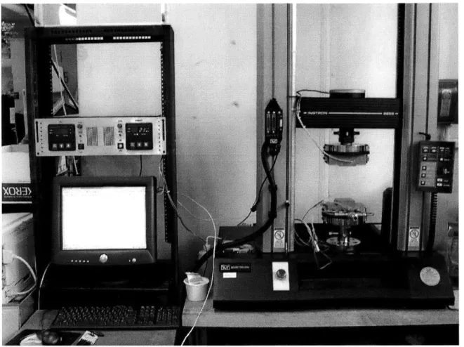
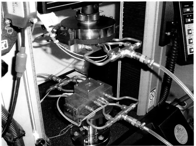
Ganesan designed and built a capable HME machine for his SM thesis at the MPCL [17]. This machine has proven useful both for his experiments and for others. An Instron model 5869 electromechanical load frame provides force and position control for the embossing platens. The platens themselves are blocks of copper heated electrically with cartridge heaters and cooled by tap water. The heaters were controlled using Chromalox 2110 controllers with temperature feedback. This apparatus is shown in figure 2-7. A close-up view of the platens and workpiece fixturing is shown in figure 2-8. The heater wires and cooling tubes can also be seen in this figure.
Figure 2-8 Generation 1 machine platens
The generation 1 machine is capable of embossing forces up to 50 kN and
temperatures up to about 300'C. Displacement of the crosshead can be controlled with a resolution of 0.0625 [tm up to a speed of 250 mm/min. This capability allows the
machine to follow arbitrary position or force trajectories within its limits, so the full range of process parameters in the position and force domains can be investigated. These parameters include embossing force, embossing strain rate, hold force, maximum tool displacement, and others.
Embossing temperatures up to 300'C can be set to ±1C, and arbitrary
de-embossing temperatures can be chosen, however the user does not have control of heating rate. Cooling is controlled with manual water valves, and so is not very repeatable or
controllable. De-embossing temperature is not controlled with precision, since the flow of water is shut off manually. Large copper blocks were needed for the platens in order to ensure even heat distribution to the workpiece and tool, and their large thermal mass limited the speed of temperature change. Typical experiments involve heating from
ambient to 130'C or higher, taking about 15min. Cooling back to ambient is more rapid, taking about 5min. The largest workpiece that can fit in the fixturing area is about 45mm by 40mm, although in practice this has been limited to about 25mm. The small size of
these test pieces served to eliminate special variation of process parameters across the workpiece and tool to eliminate a confounding factor in experiments. The tool was affixed using high-temperature epoxy to a post mounted to the upper platen. The
workpiece was clamped around its periphery by a copper plate with a hole through which the tool post could pass.
A thorough study of the HME process will require control over the temperature and temperature trajectory throughout the embossing process similar to the existing degree of control over force and displacement. Indeed, Ganesan notes that better control of process parameters is necessary to advance the level of understanding for HME [17]. Faster heating and cooling is also needed to investigate the lower end of these process parameters.
2.4.2 Commercially available HME machines
There are several capable HME machines available from commercial suppliers. The EV Group 520HE and the Suss SB6e and SB8e are adapted wafer bonding machines. Jenoptik-Mikrotechnik offers three models of hot-embossing machines. Obducat has three different embossing machines available. The capabilities of these machines are
summarized below. Obducat's product catalog gave only the maximum heat-up ramp, rather than the time to heat from 60-1800C, and did not quote cooling performance. Suss did not publish information of heat or cooling time in their web materials.
Heating Cooling Embossing
Max Max time time area
Supplier Machine Embossing Temperature 60-1800C 180-600C diameter
force (kN) (C) (min) (min) (mm)
NIL-2.5 23 250 <10C/s ? 65 Obducat [20] NIL-4 26 300 <50C/s ? 102 NIL-6 26 300 <50C/s ? 152 Jenoptik- HEX 01 20 220 7 7 130 Mikrotechnik HEX 02 200 220 7 7 130 [21] HEX 03 200 500 7 7 120 EV Group [22] 520HE 40 550 6 5 200 Suss MicroTec SB 6e 20 550 ? ? 150 [23] SB 8e 20 550 ? ? 200
Figure 2-9 Table of commercial hot embossing machines
Figure 2-12 Jenoptik HEXOl Figure 2-13 Suss SB6e
All of these machines are very able. All but the Obducat machines offer enclosed embossing chambers permitting processing under vacuum, and many have built-in automatic alignment systems for the tool and workpiece. All are able to control steady-state temperature to about ±1%. Most offer active cooling as an option.
2.5
The need for a new HME machine
While the many existing hot embossing machines are very capable, they have certain deficiencies. The existing generation 1 machine lacks closed-loop control of cooling and the ability to follow arbitrary temperature trajectories. Many commercial machines have limited capability to follow arbitrary displacement or temperature trajectories, and in most cases, direct control of the machine would be hidden behind a layer of proprietary software and hardware. To successfully and completely address the issues of manufacturing process control presented above, a new, custom-built machine is needed.
The current work addresses this need for a new embossing machine in the MPCL. The remainder of this thesis presents the design of this machine, covering the
development of design requirements, generation and selection of conceptual designs, detailed design and analysis of predicted performance of the platen assembly and the temperature control system.
CHAPTER
3
Goals for the new machine
3.1 Introduction
To extend research on manufacturing process control for hot micro-embossing, a more capable machine is needed. This machine must enable the user to precisely control the applied force and the displacement of the platens, and the temperature of the platens and thus the workpiece and tool, and to control these parameters on arbitrary time trajectories. The new machine should also incorporate improvements to allow wafer-scale processing and more automation.
The existing machine and most commercially available machines do not permit investigation of higher heating and cooling rates, and thus the ultimate limits on
embossing cycle time are not yet known. A new machine must be capable of much faster operation. Improvements in process automation over the generation 1 machine will permit more precise control and repeatable experiments.
3.2 Probing spatial variation
The generation 1 embossing machine in the MPCL had a small maximum workpiece size to ensure uniform distribution of heat and pressure across the workpiece, thus eliminating a potential confounding factor. With an eye for increasingly complex devices and higher production rates, the trend in embossing is unanimously towards larger workpieces. Larger embossing areas permit larger devices or producing several devices in one batch. Indeed, for a batch process such as this, increasing production rate
means either reducing cycle time-to which there is some physical limit-or increasing batch size. Spatial variation of process parameters across the workpiece and tool is thus an important disturbance factor needing investigation. Clever machine design can reduce this variation, but it can never be totally eliminated. An effective strategy would also involve tuning process parameters so that the sensitivity of the output to spatial variation across the workpiece is minimized.
The new machine design should, of course, minimize the non-uniformity of process parameters across the workpiece to the extent this is practical. The strategy of the generation 1 machine was to reduce the size of the workpiece to the point that variation was negligible; however, this precludes investigating the sensitivity of spatial non-uniformity to process parameters. In order to probe spatial variation and to better model potential industrial embossing, the new machine should accommodate a lager workpiece.
Traditional photolithography has remained a convenient method for making micro-features for embossing tools, so silicon wafers have long been the primary type of embossing tool [24]. Several alternative tooling materials, such as etched glass,
electroplated metal, or laser-ablated silicon are produced with techniques designed for or involving standard silicon wafers. Silicon wafers are available in standard diameters of 25, 50, 76.2, 100, 125, 150, 200, and 300mm. Wafer size has gradually increased over several decades, with the smaller sizes mostly phased out, and the largest sizes only recently introduced. The standard 100mm wafer, often referred to as a four inch wafer, is the typical size used in the embossing literature, and most commercial embossing
and research centers because its equipment is smaller and less costly, and so is also a typical platform for microfluidic, MEMS, and other related research.
Convenience, availability, and the consensus of the research community point to 100mm wafers as the target tooling size for the new HME machine. This size wafer seems to be "just right" for this purpose, being large enough to model typical polymer micro-devices, while still small enough that embossing forces and requirements for uniformity of temperature and pressure are still reasonable.
3.3 Workpiece material and thermal requirements
PMMA will continue to be the target material, as it has favorable properties for both fluidic and optical applications. The glass transition temperature for PMMA is around 1 000C, depending on molecular weight. This temperature is high enough for room-temperature stability, and low enough that an embossing machine can easily heat the workpiece above it. Prior work in the MPCL has used 1mm thick PMMA sheet at the workpiece material, while much of the embossing literature has used thinner layers of PMMA on silicon wafer substrates. The design of the new machine should not preclude either of these uses. Above about 200'C, PMMA can be considered molten, so this temperature forms the upper boundary of what should be considered embossing. Other materials, such as polystyrene and polycarbonate, could also be embossed in this temperature range.
3.4 Time-domain process parameters
A central goal for the new HME machine is that it be capable of probing the effects of time-domain process parameters. These included embossing strain rate, hold
time, and heating and cooling rates. Non-linear force, displacement, and temperature trajectories should also be possible. Even if the desired time-domain process parameter trajectories are slow and linear, the capability for precise, fast, non-linear actuation will perut robust rejection of disturbances.
The Instron model 5869 electromechanical load frame used for the existing generation 1 HME machine is a very good force and displacement actuator. It is capable of both force- and displacement-based control, and can produce a variety of waveforms in either domain, as well as arbitrary user-programmed trajectories. The load frame is capable of embossing forces up to 50kN. The Instron frame will be retained for the new machine.
The existing generation 1 HME machine had relatively slow thermal response, with heating time about 15min and cooling time about 5min. There will be an inevitable interest in driving the cycle time for embossing to the minimum, so faster thermal
response will be needed in the new machine. Thermal response is primarily a function of two aspects of the machine design-the available heat transfer power, and the thermal mass of the components subject to thermal cycling. Thermal mass is here defined as the product of an object's mass with is specific heat capacity, given in units of energy per unit increase in temperature. Thermal response can therefore be measured in the simplest sense by dividing the heat transfer power by the thermal mass, giving the maximum rate of temperature change. Fast thermal response implies a combination of a powerful heat transfer system and a low thermal mass. Thermal cycling should be limited to the fewest components possible-that is only those in direct contact with the workpiece and tool.
These components should be designed with the thermal cycle in mind. They should provide for uniform heat transfer to the workpiece and tool as well as adequate fixturing.
Ultimately, the thermal response is necessarily limited. A lower bound on what should be expected of an embossing machine may be found by estimating the amount of time a typical workpiece might take to reach thermal equilibrium with the machine. In the expected embossing application for the new machine, a 1mm thick PMMA workpiece will be cooled by contact on both sides, as shown in figure 3-1. The symmetry of this situation can be invoked to simplify the model, as shown in Figure 3-2, where T is the temperature distribution function, t is the time variable, x is the space variable, 1 is the half-thickness of the workpiece, and T, is the temperature of the platen at the surface.
Platen
PMMA
'1
..
.
Line of
Platen
symmetry
Figure 3-1 Thermal model of workpiece
x
aT0
Line of
X~
x=/symmetry
T(0,t)=
T
Platen
Figure 3-2 Simplified thermal model of workpiece with boundary conditions
The time for the workpiece to reach thermal equilibrium with the platen can be found by approximating the PMMA as an infinite slab. This approximation is valid because the width of the workpiece is many times larger than its thickness. The
one-dimensional transient heat transfer equation is given in Equation 3-1, where T is the temperature distribution, t is time, x is position, and a is the thermal diffusivity of PMMA, defined as the ratio of thermal conductivity to the product of density and heat capacity [25]. The position variable x has its origin at the bottom surface of the PMMA and increases in the vertical direction.
82T 1 T ax2 a at
Equation 3-1
The solution of this equation may be simplified by using the dimensionless temperature (D, defined in Equation 3-2, where T is the temperature at a given point at a
given time, Ts is the temperature of the platen surface, and Tj is the initial temperature of the PMMA. Substituting (D(x,t) into Equation 3-1 gives Equation 3-3.
0 T - T Oi T - T, Equation 3-2 a2q i
a(
ax
2a
at
Equation 3-3The solution of this equation is assumed to be of the form shown in Equation 3-4, where F is a function of only the position variable x, and G is a function of only the time variable t. Substituting this solution into Equation 3-3 gives Equation 3-5. Dividing the equation by the product FG gives Equation 3-6.
1(x,t)= F(x)G(t)
Equation 3-4
d2F 1 d2G G 2 =-F
Equation 3-5
I d2F 1 dG
-
=-Fdx2 a dt
Equation 3-6
The right and left sides of Equation 3-6 are independent, so they must be equal to the same constant. This equation can be separated and re-arranged to give Equation 3-7 and Equation 3-8, where -C2 is the separation constant. These equations may be easily solved to Equation 3-9 and Equation 3-10 respectively. These solutions illustrate the reason for choosing -C2. The separation constant is chosen to be negative because the temperature difference, and thus the dimensionless temperature, is expected to decay to zero over time as the PMMA comes into equilibrium with the platen. The constant is squared to make the determination of the sine and cosine coefficients cleaner.
dG =-C 2aG dt Equation 3-7 d2 F+C2F =0 dx2 Equation 3-8 G(t) = ec 2 at Equation 3-9 F(x) =
{sin(Cx)
cos(Cx)I Equation 3-10The lower surface of the PMMA is subject to a constant temperature, and the upper boundary is constrained to have zero heat transfer through the boundary. These constraints give the Dirichlet condition in Equation 3-11, and the Neumann condition in Equation 3-12, where 1 is the half-thickness of the PMMA.
Equation 3-11
= 0 ax
x=1
Equation 3-12
Because the value of cos(Cx) is 1 at x=0 while the value of ID(O,t) is constrained to a constant value of zero, the cosine solutions can be discarded. The basic solution to Equation 3-3 is thus given by Equation 3-13. The value of C can be found by imposing the Neumann condition, giving Equation 3-14, where n is a positive integer.
(= e-C "' sin(Cx) Equation 3-13 0 = e-c2 "t cos(Cl)
C
(2n -1) r 2 1 Equation 3-14The full solution is the sum of all the particular solutions. This summation is given in Equation 3-15 where Bn is the nth coefficient of the Fourier sine series given by Equation 3-16 where (o is the temperature distribution at t=0 [26]. This distribution is a constant equal to 1 for x>0 because the temperature throughout the PMMA is equal to the initial temperature. The value of the function for x<O is meaningless, so the Fourier integral is only evaluated for positive x.
i(Dx,t)= IB,e -c" sin(Cx)
n=1
Equation 3-15
1 -1
B = (-Do sin(nx)dx
(cos(nEr)q-
1)rc nir
The summation solution may be approximated by its first term, where n=1, giving Equation 3-17. The temperature at the center of the PMMA is found by setting x=l, leaving a purely exponential function. The time constant of this function is given by Equation 3-18 [27]. (D(x, t)= 1 e(/2)"' sin - x Equation 3-17 21 )2 1 7r a Equation 3-18
Using the standard definition the settling time as four times the time constant, the half-thickness of 0.5mm, and the diffusivity of PMMA of 1.23x10- m2/s, the settling
time for the temperature at the midline of the workpiece is found to be 3.29 s [27]. This time sets a lower boundary on the thermal response time of the machine. In practice, the heating or cooling time for the embossing machine will be longer, since the platens and heat transfer system will themselves have thermal masses. Without knowing the impact of fast heating and cooling on quality of the final part, it is difficult to say exactly how fast is "fast enough." There will be limits to how small the platens can be made while still accommodating the heat transfer system and allowing for fixturing of the workpiece and tool, and similarly there is a practical limit on the power of the heat transfer system. These limits are not fixed, but are based on feasibility, complexity, and cost.
3.5
Automation
Automation of the HME machine is beneficial in that it increases the repeatability of experiments vs. manual control, and it makes experiments more convenient for the
user. The Instron load frame permits automated execution of programmed force and displacement waveforms. In the generation 1 machine, the heaters are controlled to a given set point automatically, but this temperature must be adjusted manually. Cooling is entirely manual by opening and closing water valves. The temperature control and heat transfer system for the new machine should be completely automated, enabling the machine to follow pre-programmed temperature profiles just as it does for force and displacement.
3.6 Workpiece and tool fixturing
In the original generation 1 HME machine, problems were encountered in fixturing the workpiece and tool. The PMMA workpiece was clamped to the bottom platen around its periphery using a copper plate with a hole in the center through which the tool could pass. Embossing tools were mounted to the upper platen. In order to pass through the hold on the clamp plate, the tool had to be aligned properly, so the mounting holes on the tool fixture were oversized, allowing it to move a small distance laterally. The procedure involved leaving the tool fixture screws loose, running the platens together until the tool fixture mated with the hole in the clamp plate, then separating the platens and tightening the tool fixture screws. In practice, this procedure proved difficult
because the tool fixture would sometimes move before the screws were tightened, and the process had to be repeated. Misalignment between the tool fixture and the workpiece clamp plate caused damage to the tool fixture on one occasion. The new machine should incorporate improvements in the workpiece and tool fixturing that will remove the necessity that the fixtures be re-aligned after every tool change.
Both silicon wafers and machined copper pieces have been used in the generation 1 machine. Fixturing copper tools presented little difficulty because they could have integral holes for screws. Because silicon wafers are quite thin and brittle, they proved difficult to mount. Perimeter clamping was not possible because the clamp would intrude into the PMMA workpiece. Instead, silicon tools were affixed to a tool post using high-temperature epoxy. This method proved unreliable because it was difficult to ensure that the silicon tool was parallel to the tool post surface. Voids in the epoxy were sometimes present as well. Because of misalignment and possibly voids, silicon tools would
sometimes fracture under embossing forces. Adhesion between the epoxy and the silicon tools was poor, so they would sometimes break away from the tool post and remain
embedded in the PMMA workpiece. The new machine should incorporate a more accurate and reliable method for fixing thin tools such as silicon or glass wafers.
3.7 Project scope
The current work addresses the development of concepts and the detailed design and analysis of the platen assembly and the temperature control system for the new HME machine. It does not include developing an integrated control program for both the load frame and the heat transfer system. The planned design does not include an enclosed chamber for embossing under vacuum, nor does it include an active system to ensure the platens are precisely aligned.
Roos et al compared embossing under vacuum to embossing at ambient pressure, and found that uniformity across the workpiece was greater under vacuum [14]. They used a tool with features only 280nm tall, and PMMA only 300nm thick, so it is not clear that their results apply to features several microns tall and PMMA up to 1mm thick.
Bacon et al [15] using the same embossing apparatus found that uniformity across the part also varied with other processing conditions such as embossing temperature and force, suggesting that with proper selection of embossing conditions, vacuum may not be necessary for uniform imprinting. Indeed, results by Ganesan [17] and continuing experience with HME in the MPCL have demonstrated very good embossing for features at this scale, without the need for vacuum. A vacuum chamber would increase the complexity of the embossing machine, while the necessity of a vacuum environment has not yet been demonstrated.
The current design also does not incorporate an alignment system for the two platens. Such a system could be anything from passive alignment using beams and slide bearings to closed-loop, actuated control of the platen alignment in up to five degrees of freedom. Past experience in this lab has shown that the alignment accuracy of the Instron load frame is adequate to produce good results. Any misalignment resulting from
tolerances in the machined parts does not vary over time, so these misalignments can be compensated for with shims and other adjustments. Although the current design does not include a vacuum chamber or active alignment system, it should not preclude their
addition at a later date.
3.8 Summary of goals for the generation 2 HME machine
The generation 2 HME machine is intended to meet the demands of an extensive investigation of HME from a manufacturing process control perspective. It is intended to enable experiments across the practical range for all process parameters, including time domain parameters. It will accommodate a workpiece up to 100mm in diameter to study spatial variation across the part, it will permit faster experiments and probing of the
ultimate limits to HME cycle time, and it will enable full automation of both the force and displacement control and the temperature control. The new machine should also permit more reliable fixturing for tools and workpieces.
CHAPTER
4
Concept development and evaluation
4.1 Introduction
The generation 2 HME machine will incorporate numerous improvements over the existing machine. The most important of these improvements addresses the lack of precise control over the temperature-time trajectory. Reducing the cycle time,
incorporating full automation, and improving fixturing are also important requirements for the new machine. To proceed with the design for the new machine, conceptual designs to meet each important function were developed and evaluated. The concept that proved most likely to meet the requirement was selected for the detailed final design.
4.2 Temperature control
Improving control over the temperature-time trajectory and reducing heating and cooling time are the central, defining requirements for the new machine design. The method for heating and cooling the platens to control the temperature of the workpiece will drive the design of the platens themselves, so the temperature control subsystem must be defined before the design of the platens can proceed.
The temperature control system must be able to add or remove heat energy to the platens in order to change their temperatures. There are three domains of heat transfer-conduction, convection, and radiation-and all should be considered for the temperature control system. Conduction will necessarily be the operative mode of heat transfer within the platen and fixture assembly, but the manner of heat transfer to and form this assembly
could be of another form. A source of heat energy is needed to add energy to the platen assembly and increase its temperature, and an energy sink is needed to remove energy and decrease temperature. Many methods for generating and dissipating heat energy exist, however some are better suited to a laboratory environment.
Whatever method is chosen must be capable of producing heat transfer rates sufficient to meet the heating and cooling time goals. Rough estimates for the minimum total power may be found by multiplying the thermal mass of the workpiece and tool by the desired temperature change, and dividing by the desired time to change. The
workpiece and tool are taken to be 100mm diameter circles. The workpiece is PMMA 1mm thick, and the tool is silicon 0.5mm thick, giving thermal masses of 13.6 J/0K and 6.4 J/0K respectively. For a temperature change from 25*C to 150'C, this gives a total energy change of 2.5kJ. To accomplish this temperature change in 2 minutes would require an average power of 21W. In practice, however, some of the heat input must go to changing the temperature of the platens, so the required power will be higher.
4.2.1 Thermoelectric (Peltier)
A fully electric system would have the advantage of being physically simple and clean. Furthermore, the mechanism of heat transfer would be in the same domain as the electrical control and feedback signals, reducing the number of conversions between domains of energy and resulting in higher efficiency. This is made possible via the Peltier effect, whereby a temperature difference is created by current passing through dissimilar materials. Because the polarity of current determines the direction of heat transfer, heating and cooling may be accomplished using the same hardware simply by reversing the current. Peltier effect heaters and coolers are available with power ratings
sufficient for the heating and cooling time goals, and some can operate at typical embossing temperatures [28].
Although Peltier effect heating and cooling is attractive for temperature control in embossing, certain physical realities render it infeasible. The first problem with solid-state Peltier effect devices is structural. Commercially available thermoelectric devices are not designed to resist compression or tension loads, so some additional structure would be needed to support the workpiece and tool. This structure would increase the total thermal mass, so power requirements would increase. The second problem is thermodynamic. The Peltier effect does not create or destroy heat energy, but merely moves it from one place to another. Thus, when heating the workpiece and tool, the other junction must have a source of heat, and when cooling, this junction must be exposed to a heat sink. To produce the large changes in temperature encountered in embossing would still require an additional heat transfer system to alternately heat and cool the Peltier devices themselves, although the requirements on this system would not be as stringent as on one that heated and cooled the workpiece and tool directly.
The Peltier effect has been successfully exploited for cooling of microelectronic devices, but is not adequate for the bulk heating and cooling encountered in hot
embossing. Peltier devices could conceivably be integrated into the platens to produce relatively small, localized temperature variations.
4.2.2 Mixed electric & fluid
The method of temperature control employed by the generation 1 machine consists of a mixture of heat transfer strategies. Heat energy is added to the platens by conversion from electrical energy though Joule heating. The heat flux from electric
cartridge heaters is controlled by adjusting the current flowing through them. Heat is removed from the platens by convection to water flowing through passages in the platens.
Precise temperature control along arbitrary trajectories is not possible with the original setup, but this method of temperature control could be adapted for the new machine to allow this capability. The flow rate of cooling fluid could be adjusted to modulate cooling while the current through the heaters is adjusted to control heating. Balancing the heat flux into the platens from the electric heaters with the flux out of the platens to the cooling fluid would permit temperature control. In practice, this strategy would be difficult to implement. The relationship between flow rate and heat flux for convection in tubes is extremely non-linear, exhibiting an abrupt jump in heat transfer across the transition from laminar to turbulent flow.
This effect could be mitigated by running the cooling fluid at a constant flow rate and varying the output of the electric heaters. For cooling, the heaters would be adjusted so the heat flux into the cooling fluid is greater than the heat generated by the heaters, and for heating the current would be increased so the heaters overpower the convective
cooling. This strategy requires that the heaters be very powerful, effectively doubling the power needed. Temperature control would be inherently difficult because one has
control over heat fluxes, rather than temperature directly. A steady temperature is accomplished by making the heat flux from the heater and the heat flux into the cooling fluid equal, and changes in temperature are effected by adjusting the net heat flux into the platens. When the heat fluxes are balanced, temperature will not change, but this steady temperature does not depend on the values of the heat fluxes, indeed any absolute heat flux could maintain any steady temperature so long as it is balanced.
![Figure 4-4 Diagram of plate and frame heat exchanger [30]](https://thumb-eu.123doks.com/thumbv2/123doknet/14684147.559874/51.918.215.703.216.584/figure-diagram-plate-frame-heat-exchanger.webp)