Desiccant Dehumidification Analysis
By
Hai-Yun Helen Xing
B.S., Mechanical Engineering (1998) Tsinghua University
Submitted to the Department of Architecture In Partial Fulfillment of the Requirements for the Degree of
Master of Science in Building Technology
at the
Massachusetts Institute of Technology September 2000
Copyright 2000 Massachusetts Institute of Technology All rights reserved
Signature of the author... ... Department of Architecture
August 4, 2000
Certified by...
Leon R. Glicksman Professor of Mechanical Engineering and Building Technology Thesis co-advisor 17
C ertified by ... . ... . . . ... .. . . .. . . .. . Leslie K. Norford Associate Professor of Building Technology A Thesis co-advisor A ccep ted b y ... . ... ... . ... ...
Stanford Anderson MASSACHUSETTS INSTITUTE Chairman, Department committee on Graduate Student
OF TECHNOLOGY Head, Department of Architecture
SEP 2 1 2000ROTC
Desiccant Dehumidification Analysis
By
Hai-Yun Helen Xing
Submitted to the Department of Architecture on August 4, 2000 in Partial Fulfillment of the Requirements for the Degree of Master of Science in
Building Technology
ABSTRACT
Desiccant dehumidification has been given increasing interest in the air conditioning industry. Compared with conventional vapor compression air conditioning systems, desiccant dehumidification saves energy by separating humidity control from temperature control and also improves the indoor air quality as a good filter. This research explores the potential of applying desiccant dehumidification systems in buildings with less energy consumption.
As the first step, the adsorption mechanism is explored and desiccant material properties are obtained based on a literature review. The heat and mass transfer in the desiccant - moist air system is well understood and modeled using both pseudo-gas-side controlled (PGC) transfer coefficients and semi-infinite transfer coefficients. Compared with experimental data, the model well predicts single processes while the prediction for cyclic processes is acceptable for practical applications. This model provides a useful tool for two purposes: analysis of desiccant unit's performances and optimization of the design and operations of a unit. Based on the semi-infinite body theory, the semi-infinite model provides a way to simplify the solid-side diffusion resistance.
A temperature control strategy is proposed to improve the mass transfer efficiency. A design in which the desiccant temperature is controlled in sections is tested using the model developed before.
Simulations show that temperature control enhances mass transfer. Using the model, parametric analysis is conducted on a temperature-controlled packed-bed desiccant unit. The effects on
dehumidification performances of processing air mass flow rate, regeneration temperature and cycle time are studied. Parametric analysis gains insight into the correlations and interactions between different operation parameters.
Three criteria are put forward to evaluate the performances of a desiccant dehumidification system for building applications: adsorption rate, average outlet air parameters and energy consumption. A
systematic way is proposed to size a desiccant unit and optimize its operations by using the model developed before. In a case study a desiccant unit is designed for a two-people room in Shanghai for ventilation purposes and the unit's operations are optimized. The design results show that desiccant dehumidification can be used in building applications, provided appropriate operation parameters are adopted. The yearly operations of a desiccant dehumidification system are proposed.
Thesis co-adsisor: Leon R. Glicksman
Title: Professor of Mechanical Engineering and Building Technology Thesis co-advisor: Leslie K. Norford
TABLE OF CONTENTS ABSTRACT LIST OF FIGURES LIST OF TABLES NOMENCLATURE CHAPTER 1 1.1 1.2 1.3 1.4 INTRODUCTION Background Literature Review
1.2.1 General Research Review 1.2.2 More Related Research
1.2.3 Research Institutes and Industry Involved Thesis Objectives
Procedures
CHAPTER 2 DESICCANTS AND ISOTHERMS 2.1 Desiccants and the Physical Properties 2.2 The Characteristics of Desiccants
2.2.1 Isotherms
2.2.2 Heat of Adsorption
2.2.3 Isotherm Classification and Adsorption Mechanisms 2.3 Silica Gels
CHAPTER 3 HEAT AND MASS TRANSFER BETWEEN SOLID PARTICLES AND MOIST
AIR 5
3.1 Heat and Mass Transfer Process 3
3.1.1 the Heat Transfer Biot Number 4
3.1.2 Mass Transfer Mechanisms 4
3.1.3 the Mass Transfer Biot Number 4
3.2 Overall Transfer Coefficients 4
3.2.1 Solid Side Resistance Model 4
3.2.2 Pseudo-gas-side Controlled Model 4
CHAPTER 4 MODELING OF HEAT AND MASS TRANSFER IN DESICCANT UNITS
4.1 Packed-beds and Rotary Wheels
4.2 Heat and Mass Transfer Governing Equations 4.2.1 Control Volume and Assumptions 4.2.2 Governing Equations
4.3 Numerical Scheme 4.4 Model Validation
4.4.1 A Limiting Case 4.4.2 Overall Mass Balance 4.4.3 Single Process Validation 4.4.4 Cycle Process Validation
4.5 Validation Using the Semi-infinite Body Model 4.5.1 Single Processes
4.5.2 Cyclic Processes
CHAPTER 5 DESICCANT UNIT DESIGN AND ANALYSIS
5.1 The Analysis Frame
5.1.1 Performance Criteria 5.1.2 Air Processing Procedure 5.1.3 Desiccant Units
5.2 Desiccant Temperature Control Strategy 5.2.1 Why Temperature Control 5.2.2 How to Control
5.2.3 How Temperature Control Works 5.2.4 Another Temperature Control Scheme
5.3 Parametric Analysis on Temp-controlled Desiccant Units 5.3.1 Mass Flow Rate
5.3.2 Regeneration Temperature 5.3.3 Cycle Time
CHAPTER 6 6.1 6.2 CHAPTER 7 7.1 7.2
PRELIMINARY ANALYSIS OF DESICCANT SYSTEMS Design A Desiccant System - A Case Study
Yearly Operations of Desiccant Dehumidification Systems
CONCLUSION AND WORK IN THE FUTURE Conclusion
Research in the Future
7.2.1 Solid Side Resistance Models
7.2.2 Desiccant Unit Design to Enhance Mass Transfer
7.2.3 Fan Power Considerations and Laminar Flow Passage Wheels 7.2.4 New Materials
7.2.5 System Design, Analysis and Operations
REFERENCES
APPENDIX A
- THERMAL DYNAMIC RPOPERTIES OF MOIST AIR AND DESICCANTS
APPENDIX B
- DEVELOPMENT OF THE SEMI INFINITE MODEL
APPENDIX C
- GOVERNING EQUATION DEVELOPMENT
APPENDIX D - CODE 104 104 109 112 112 113 113 113 113 114 114 115 117 120 125 130
LIST OF FIGURES
Figure Page
1.1 Air processing in desiccant dehumidification vs. vapor compression 19 dehumidification
1.2 Cycle of adsorption and desorption 20
1.3 Desiccant wheel 20
1.4 Conceptual diagram of the desiccant dehumidification and cooling system 22
1.5 Pennington ventilation cycle 24
1.6 Desiccant enhanced cooling 26
2.1 Isotherms of silica gel 32
2.2 Isotherms of various desiccants 32
2.3 Characteristics of five classical isotherms 33
2.4 Adsorption isotherms 35
2.5 Isotherm comparison 36
4.1 Schematic of a packed-bed system 54
4.2 Desiccant control volume for heat and mass transfer analysis 56 4.3 Fluid temperature variance along a balanced counter flow exchanger 61 4.4 Limiting case study: pseudo counter flow heat exchanger 61
4.5 Dehumidification validation using the PGC model 65
4.6 Dehumidification on isotherms: degradation of desiccant adsorption ability 66 4.7 Temperature profiles at the beginning period of dehumidification 67
4.8 Regeneration validation using the PGC model 68
4.9 Cyclic process validation on psychrometric chart using the PGC model 70 4.10 Cyclic process on isotherms: adsorption, switched from desorption 71 4.11 Dehumidification validation using the semi-infinite model 74 4.12 Regeneration validation using the semi-infinite model 75 4.13 Cyclic process validation on psychrometric chart using the semi-infinite model 76
5.1 Air processing procedure: ventilation mode 80
5.2 Desiccant temperature control vs. non-control in dehumidification on isotherm 82
5.3 Section temperature control design 84
5.4 Three temperature control cases to be compared 85
5.6 Average air states along the flow direction in dehumidification 87
5.7 Performance comparison of different temperature control strategies 88
5.8 Effects of section numbers on adsorption performance 89
5.9 Effects of the high heat capacity scheme on adsorption performance 91
5.10 Performance comparison of different temperature control strategies 92 5.11 Adsorption rate changes with processing air velocity 94 5.12 Outlet air parameters changes with processing air mass flow rate 95 5.13 Adsorption rate and outlet air humidity change with regeneration temperature 96 5.14 Effect of cycle time on adsorption rate and outlet air humidity: increasing total 97
time and constant time ratio
5.15.1 Effect of cycle time on adsorption rate and outlet air humidity: 98 constant total time and increasing time ratio (1)
5.15.2 Effect of cycle time on adsorption rate and outlet air humidity: 99 constant total time and increasing time ratio (2)
5.16 Pressure drop changes with air velocity for a packed-bed unit 101 5.17 Fan power changes with air velocity in a case study 102 5.18 Fan power changes with air velocity, the thinner desiccant unit 102 6.1 Air processing in a desiccant dehumidification system in Shanghai 104 6.2.1 Outlet humidity changes with processing air velocity and cycle time, case study 106 6.2.2 Adsorption rate changes with processing air velocity and cycle time, case study 106 6.2.3 Fan power changes with processing air velocity, case study 107 6.3 Yearly operations of a desiccant dehumidification system 110
LIST OF TABLES
Table Page
2.1 Properties of common commercial desiccants 31
2.2 Material properties of GradeO1 regular density silica gel 38 3.1 Heat transfer Biot numbers for RD silica gel d = 4mm, 0.5 w/mk 41
3.2 Diffusion coefficient comparison for RD silica gel 43
3.3 Mass transfer Biot numbers for RD silica gel d = 4mm, 2e-9 m2/s 45 3.4 Properties of RD silica gel for Fourier number calculation 49 3.5 Fourier numbers for RD silica gel at different reaction times 49
3.6 Transfer coefficients used in three models 53
4.1 Limiting case study: a pseudo counter-flow heat exchanger 62
4.2 Experimental set-up for adsorption 64
4.3 Experimental set-up for desorption 64
4.4 Experimental set-up for a cyclic process 69
4.5 Comparison of PGC simulation with experiment for a cyclic process 72 4.6 Comparison of Semi-infinite simulation with experiment for a cyclic process 77
5.1 Parameters of the desiccant unit used in performance analysis 81
5.2 Three temperature control cases to be compared 85
5.3 Unit and operation parameters of the high heat capacity scheme 90
5.4 Geometry of the desiccant unit in pressure drop calculation 101 6.1 Design parameters of the desiccant unit used in a case study 105
6.2 Operations of the desiccant unit used in a case study 105
6.3 Design results in a case study 108
NOMENCLATURE
A
transfer area m2AU free flow area in the desiccant unit m2
A, cross section area of the desiccant unit m2
a radius of pores in desiccant m
h d
Bh Biot number for heat transfer Bih=
Kd
hd B.,,, Biot number for mass transfer Bi, = k, p
PdD Cba specific heat of humid air
J/kgK
Cbd specific heat of wet desiccant J/kgK Cd specific heat of the desiccant J
/
kgK Cp, specific heat of dry air J/
kgKCp.,
specific heat of water vapor J/
kgKC,,
specific heat of water J/
kgK d, particle diameter mDH2 ,airordinary diffusion coefficient m2 /s DK Knudsen diffusion coefficient m2
/s
Ds
surface diffusion coefficient m2 IsDsegf efficient surface diffusion coefficient m2 s 6,, free flow ratio c,, ,/ A,
F, Fourier number
h heat transfer coefficient W /m 2
K
had adsorption heat J / kg
hc convective heat transfer coefficient W /m2K
h f latent heat of evaporation J / kg
hg
enthalpy of water vapor J / kgh,,, mass transfer coefficient
kg /
m2sAh, integral heat of wetting J / kg
Hair enthalpy of humid air J /
kg
Hdes enthalpy of wet desiccant (energy content per unit mass dry desiccant) J/ kg
kd thermal conductivity of desiccant W / m K kair thermal conductivity of air W / m K
L length of the desiccant unit m
mair mass flow rate of the air stream per unit area
kg /m
2s m water mass flow rate of water in desiccant particleskg / m
2s
Mair mass flow rate of the air stream
kg
/ sMair humidity ratio of moist air kg water /kg dryair
Md humidity ratio of the air layer on desiccant particle surface kg water
/kg
dryairMR mass ratio of a desiccant unit MR =PA
mair '
NTU number of heat transfer unit NTU = hPL mair
CPa
NTU number of mass transfer unit NTU,,, hPL
m
airNu Nusselt number Nu =
h dp
kdPair density of dry air kg /
rn
3ph bulk density of the desiccant kg /M 3 Pd density of desiccant particle kg / Mr
PI11. water vapor partial pressure of humid air Pa
Pr Prandtl number Pr =
-a
P transfer perimeter of the desiccant unit M2 /M (transfer area per unit length) q heat flux J / s
r radius of particles, length scale in the sphere coordination m
R thermal resistance k
/
WRe Reynolds number
RH relative humidity of humid air
Sh Sherwood number Sh = h,,d
pD
Sc Schmidt number Sc=-D
t time scale s t dimensionless timeTair temperature of moist air C
Td temperature of desiccants and the air layer C Td, processing air temperature C
T,. regeneration air temperature C
Vd, processing air velocity m / s
Vre
regeneration air velocitym / s
V
volumetric flow rate m3/s
Wd water content in desiccants, dry weight basis W fan power w
x length scale m x* dimensionless length
Greek symbols:
p dynamic viscosity
kg / n s
a thermal diffusivity m2 Is
7
kinematic viscositym
2 /s -T, surface tortuosity factorSubscripts:
air dry air C convective conv convection cond conduction d desiccant de dehumidification diff diffusion e ambient environment
eff effective value
eq equilibrium between desiccant and surface air layer
h heat transfer H20 water
m mass transfer p desiccant particle
re regeneration
s surface of desiccant particles
sat saturation
eff effective WV water vapor
CHAPTER 1 INTRODUCTION
1.1 Background
A significant fraction of the energy in air-conditioned buildings is required for the removal of moisture. Depending on locations in the United States, this energy, which is used to remove the latent heat of condensation and the sensible heat in cooling the condensed water onto the coils of the mechanical refrigeration system, can account for up to 30% of the energy used in air conditioning [28]. It is the goal of the desiccant dehumidification industry to remove water from processing air before it is mechanically refrigerated, and to utilize a low-cost heat resource for regeneration.
Desiccants are materials that upon contact with moist air at moderate temperatures exhibit a great affinity for water vapor. There are two main groups of desiccants: solids and liquids. Solid desiccants are porous materials. The water vapor molecules condense and adhere to the surface of the pores. This surface effect is called physical adsorption. Liquid desiccants incorporate the condensed water vapor molecules into their bulk. This volumetric effect is physical absorption. The term sorption has been adopted to describe both processes. Internal energy is released during the sorption process.
Consequently, warm and humid air passing through desiccants becomes hot and dry. Desiccants continue to adsorb moisture as their sorption ability gradually decreases. At some point, desiccants become saturated to the degree required in a particular process and sorption ceases. Hot air must be brought into contact with desiccants to regenerate them. In regeneration, the moisture is transported from desiccants to regeneration air. When desiccants get dry enough, the process is switched back to dehumidification and another operation cycle starts.
200
Ref rigeration Dsca
100%/ rh10 I
Fig. 1.1 Air processing in desiccant dehumidification vs.
vapor compression dehumidification 0
30 Temperature ( *F) 140
Fig. 1.1 [1] shows how the condition of moist air changes in dehumidification on a psychrometric chart. Usually, the heat transfer rate between the desiccants-moist air system and the outside environment is small and can be ignored. So the adiabatic procedure is a reasonable assumption. The cyclic process of sorption /desorption for desiccants is shown in Fig. 1.2.
2500 F
2000 F Desorption
Rotary Honeycombe
desiccant wheel
/1500
FDesiccant moisture contert
Fig.l1.2 Cycle of adsorption and desorption Fig. 1.3 Desiccant wheel
In recent years, desiccant dehumidification has been given increasing interest in the air conditioning industry. Compared with conventional vapor compression air conditioning systems, desiccant dehumidification has at least two advantages.
First, desiccant dehumidification separates humidity control and temperature control. In conventional air conditioning systems, air has to be cooled to dew point to remove moisture. In some cases such as supermarkets, humid air is overcooled to achieve low humidity, which degrades the energy efficiency. Desiccant dehumidification has nothing to do with dew point. It can adsorb moisture at almost any humidity level.
Second, desiccants have been found to act as a good filter for contaminants [2]. In addition to removing particulate contaminants, desiccants condense vapor contaminants out of the air. Desiccants are
mold, caused by using water in conventional systems do not occur in desiccant dehumidification. So, desiccant systems have a good potential to improve the indoor air quality.
The idea of using solid desiccants for dehumidification and cooling was originally proposed by Dunkle in the middle 1960s. There are two types of desiccant equipment according to the purposes of
dehumidification and cooling. One is a dehumidifier, which pays more attention to removing moisture from process air. The other is an enthalpy exchanger, which emphasizes the energy recovery from return air to fresh air by using desiccants. These two different functions determine different desiccant properties and system designs. For example, the enthalpy exchanger favors higher desiccant specific heat for energy storage. This research will focus on the dehumidifier type.
Rotary desiccant wheels and fixed beds are the most common desiccant dehumidifier configurations. Fig. 1.3 shows the scheme of a rotary desiccant wheel. Rotation allows continuous operation, but limits the use of the wheel because it is inconvenient to have a rotating component in some places. In contrast, a desiccant bed is flexible in positioning but cannot run continuously. Usually, more than one desiccant bed unit is used to compensate for the non-continuous drawback. One bed can be in regeneration while another is in dehumidification.
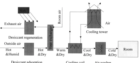
Fig.l .4 shows an example of a desiccant dehumidification system. It is a conceptual solar desiccant system that will be analyzed in this research. Like most desiccant systems, this solar desiccant system has two processes: adsorption stage, dry cooling and evaporative cooling on the dehumidification side; heating and desorption stage on the regeneration side. In this research, hot and dry air out of the desiccant unit is cooled down by cooling tower water in the coils. It gets additional cooling in the evaporative cooling coil, reaches the desired condition, and is supplied into the room. The room air is used as regenerating air. Solar energy is the regeneration resource.
0Z
E
Exhaust air Air
Cooling tower Desiccant regeneration
Outside air
I
Hot Hot Wam Cool Cold Rom
&Humid &Dry &Dry &Dry &Dry Desiccant adsorption Cooling coil Air washer
Fig. 1.4. Conceptual Diagram of the Desiccant Dehumidification and Cooling System
1.2 Literature Review
Extensive experimental and simulation studies have been done in the field of desiccant
dehumidification. A general research review is put forward first aimed at getting a big picture about what researchers have done in this field. Depending on the goal of this research, some closely related references are discussed afterwards. At last, the current research environment including the federal government, national labs and companies is mentioned, which has been providing useful information to this research.
1.2.1 General Research Review
The following fields have been given more attention: solid side mass transfer model; desiccant materials and adsorption mechanism; desiccant system performance analysis and optimization; and new desiccant systems.
Different from many other transport problems in the HVAC industry, transport in the solid phase plays a key role in desiccant dehumidification. The heat conduction resistance and mass diffusion resistance in desiccant particles must be considered, which makes the analysis much more complex. Tremendous efforts have been spent on understanding the mass diffusion mechanism in solid particles and measuring and calculating the mass diffusion coefficients for certain materials. The difficulty lies in the fact that the researcher can hardly get accurate information to account for the transfer resistance inside desiccant
proposed. For example, Pseudo-Gas-Side Controlled model by Marshall [3], Surface diffusion esistance model by Kruckels [4], Solid-side resistance model by Pesaran [5] and the parabolic concentration profile model by Chant [2]. Some models got poor prediction results.
Desiccant material properties no doubt are the most important parameters in desiccant systems. The system performance largely depends on what kind of desiccant is used. Looking for promising desiccants has always been an interesting research field. In the mean time, accurate isotherms for specific desiccants are also very important. Brunauer [6] classified experimentally observed isotherms
into five types that characterize different adsorption mechanisms, which will be discussed in chapter 2. Rojas [7] obtained pure vapor adsorption isotherms of water vapor on five grades of silica gel. The theory of multilayer adsorption with correction for adsorption by capillary condensation was used to correlate the data. Pesaran [5] fitted manufacturers' data for grade 01 and grade 59 silica gel, which have been widely used in the dehumidification industry. Based on the research in the Gas Research Institute, Novosel [8] found out that the moderate Brunauer Type I isotherm (Type 1 M) represents the best compromise when applied to comfort conditioning using high temperature regeneration. System designs employing Type 1 M desiccants can meet and exceed the performance of conventional
electric-driven unitary air conditioners.
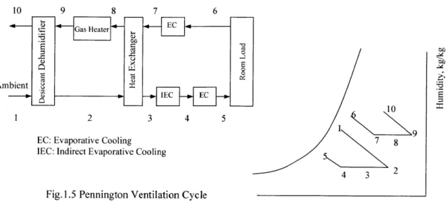
Compared with vapor compression air-conditioning systems, desiccant systems need many more parameters to describe their design and operation. Analyzing how those parameters affect the system performance is a very challenging job. Extensive research has been done to explore many kinds of desiccant applications. The Pennington cycle is a widely-used desiccant system in the literature. Fig. 1.5 shows the Pennington cycle and the corresponding psychrometric process. Fresh air is
processed through desiccant dehumidification, dry cooling and evaporative cooling before it is sent into the room. In the mean time, the room air is heated in an evaporative spray chamber and a gas heater, and is used to regenerate the desiccant. The open cycle desiccant air conditioning system that Jurinak [9] proposed is an example of a Pennington cycle. Chant [2] investigated the desiccant enhanced cooling (DEC) system in which desiccants assist in improving the cooling efficiency of vapor compression systems.
10 9 8 7 6 Gas Heater EE 01 Ambient8:: 1 2 3 4 5
EC: Evaporative Cooling 7 8
IEC: Indirect Evaporative Cooling
4 3 2
Fig. 1.5 Pennington Ventilation Cycle
Temperature, C
1.2.2 More Related Research
Ahlberg [10] obtained experimental data for rates of water adsorption from air by silica gel packed particle beds for various air flow rates and particle sizes. The data were used by Hougen and Marshall
[3], who analyzed adiabatic and isothermal bed operation using graphical techniques. For this purpose, they assumed a model in which the particles have a uniform moisture content and temperature, and the overall transfer process could be represented by pseudo-gas-side transfer coefficients. With appropriate model equations, they found that Ahlberg's data could be recovered using the following correlations for the transfer coefficients:
heff = 0.6 8 3 mair Re -0.4 2
Cpa W/m 2 K 1.1
h,,eff = 0.704 mair Re-042 kg/n 2 s
1.2 Where
mair mass flow rate per unit area kg
/m
2s
CPa specific heat of air J/ kgK
This pseudo-gas-side controlled model (PGC) was then used by many investigators later on.
Pesaran [5] deeply studied moisture transport in silica gels. A heat and mass transfer model in silica gel particle beds was developed with special attention paid to the modeling of solid side resistance. For this
silica gel was made, which explained different diffusion mechanisms and gave corresponding formulas of diffusion coefficients. Both Knudsen and surface diffusion were found to be important mechanisms of moisture transport in intermediate density gels (mean pore radius 68 nm). Surface diffusion was found to be the dominant mechanism of moisture transport in regular density silica gels (mean pore radius 1 Inm). A general equation for moisture transport in a spherical silica gel particle was developed and called the solid-side resistance model (SSR). The SSR model was incorporated into the model equations governing heat and mass transfer between desiccants and the process air. Both adsorption and desorption experiments were performed for regular density silica gels. The agreement between theory and experiment was good.
Chant [2] dealt with the solid side resistance in a different way. She solved the diffusion equation for moisture transport in the solid side by assuming a parabolic water concentration profile (PCP) inside the particle. Based on the PCP model, a heat and mass transfer model for a desiccant wheel with laminar moist air flow was developed. Both periodic steady state and transient solutions were investigated. Simulation results matched the experimental data. This transfer model was used to perform simulations of an innovative desiccant-assisted cooling system called desiccant enhanced cooling (DEC), shown in Fig. 1.6. In the DEC cycle, return air enters the desiccant dehumidifier, adsorbs moisture and gets closely saturated. Then it enters the following cooling coil which performs increased dehumidification. After exiting the cooling coil, the incoming air stream undergoes additional dehumidification in the desiccant dehumidifier. The phase change energy released acts as the free reheat energy. The simulations showed that the DEC system is more efficient to handle the latent heat than a vapor compression unit. The investigation of coefficient of performance (COP) and pressure drop of DEC systems indicated that the DEC system was promising. A second law analysis was conducted to gain more insight into the energy losses in DEC systems.
2
Supply Air 1
Return Air Cooling Coil
SA Rotary Desiccant Dehumidifier
Temperature, C Fig. 1.6 Desiccant enhanced cooling
San and Jiang [11] modeled and tested a two-column packed-bed silica gel dehumidification system. Desiccants were continuously switched between adsorption and desorption in two desiccant columns. The SSR model was used to simulate this cyclic process and periodic steady-state solutions were obtained. The effect of fluid friction on solid side resistance was given more attention when developing the heat and mass transfer model. The experiment and simulation showed this friction effect became more important with higher Reynolds number. The effects on humidity removal of regeneration temperature, inlet air humidity, operating cycle time and column length were investigated. The higher the regeneration temperature or the longer the desiccant column, the more the system uptake. The optimum cycle time corresponded to the operation with a maximum humidity removal. The humidity removal linearly increased with a decrease of the inlet air humidity ratio.
Jurinak [9] used an analogy solution of a rotary heat and mass exchanger and the finite difference method to simulate a counterflow rotary dehumidifier. The desiccant matrix's properties were analyzed
in detail from the aspects of isotherm shape, the heat of sorption, the maximum sorbent water content, sorption isotherm hysterisis, matrix moisture diffusivity and matrix thermal capacitance. An open cycle desiccant air conditioning system was proposed. It used a solid sorbent matrix to dehumidify the processing air stream that was subsequently cooled and used directly to meet an air conditioning load. The open cycle desiccant system was analyzed as an alternative to vapor compression cooling in residential applications due to its potential to improve the energy efficiency.
Pesaran and Hoo [12] pointed out that the performance of a solar desiccant cooling system particularly depends on the performance of the desiccant dehumidifier and the solar collectors. The effects of the
isotherm shape and the regeneration temperature on desiccant dehumidifier were studied. The effect of the solar collector's operating temperature, which is very close to the desiccant regeneration
temperature, was also investigated. Optimum performance is explored based on the thermal coefficient of performance and cooling capacity.
Smith et al. [13] developed a mathematical model of a solar-assisted desiccant air conditioner and simulated its performance in residential buildings. Based on the air conditioner model developed, a cooling system was designed. The performance of this cooling system was evaluated at various locations by means of computer simulations. Results indicated that desiccant air conditioning could meet the cooling loads present in the three locations evaluated. Desiccant cooling appears to be well matched to the available solar resources in the southwestern U.S. However, it appears that a significant amount of auxiliary energy is required to power the system in the northeastern and, in particular, the southeastern U.S.
1.2.3 Research Institutes and Industry Involved
An industry-coordinated program is critical to the success of the technology. In response, the Dept. of Energy (DOE) is collaborating with the U.S. Air Quality (USAQ) consortium and industry to conduct desiccant technology research and technical support to industry. Partners in the USAQ consortium include the American Gas Cooling Center Inc. (AGCC), the Gas Research Institute (GRI), gas utilities, desiccant equipment manufacturers and HVAC equipment manufacturers. Near-term goals focus on developing the next generation of desiccant equipment for broader commercial applications. Long-term goals focus on developing second-generation, advanced desiccant systems for broad commercial and residential applications. The National Renewable Energy Laboratory (NREL) and Oak Ridge National Laboratory (ORNL) are managing the program jointly for DOE and offering technical support to industry through industry partnerships.
1.3 Thesis Objectives
Desiccant dehumidification is new to the Building Technology program at MIT. This work aims at exploring and getting a big picture of this field. At the end of this work, we should have a clear image about the challenges and opportunities that researchers are facing in this field. The process physics should be well analyzed and simulated. The potential of applying desiccant dehumidification systems in building applications should be evaluated.
As a first step, desiccant materials, desiccant adsorption mechanisms and the heat and mass transfer in desiccant -moist air systems should be well understood.
Solid side resistance is a key issue to desiccant dehumidification. There are roughly two types of models regarding this issue. One is a PGC (pseudo-gas-side controlled) type model that considers the solid side resistance by degrading the gas-side transfer coefficients based on experiment. The
empirically degraded transfer coefficient is of questionable accuracy. Plus, it has been determined only for some very common desiccant dehumidifiers, such as a silica gel packed bed, and is not available for many other materials. The other is a SSR (solid side resistance) type model which analyzes the solid side resistance in detail. However, it requires solving the second order diffusion equation and computation becomes much more complicated. So, how to efficiently deal with the solid side resistance becomes very challenging.
In this research, the heat and mass transfer between desiccant particles and moist air is analyzed and modeled. A semi-infinite model is proposed aimed at simplifying the solid side resistance analysis. Mass transfer in desiccant particles can be considered a semi-infinite body transport problem.
The temperature variance of desiccants in adsorption/desorption degrades the desiccant
dehumidification/regeneration performance. Keeping desiccant temperatures as uniform as possible is useful to improve the desiccant system performance. This possibility has not been given attention in previous research. In this work, a design of controlling desiccant temperatures in sections is proposed and its performance is studied with comparison with non-control cases. A temperature control scheme of using high heat capacity with preheating/precooling is analyzed conceptually. Researching on temperature control also contributes to better understanding of adsorption mechanisms.
The parametric analysis is conducted on the packed-bed type desiccant unit. The effects of mass flow rate, cycle time, regeneration temperature on desiccant unit performance are analyzed. Pressure drop and power required are estimated. The parametric analysis helps improving unit designs based on performance evaluation.
A case study shows how to optimally design a desiccant unit for a certain building application. A yearly-operation proposal for the desiccant dehumidification system is discussed.
Eventually, we would like to know how much potential the desiccant dehumidification system has to provide comfort conditions in buildings with less energy consumption.
1.4 Procedures 1. Model
Develop a heat and mass transfer model for desiccant-moist air systems by using pseudo-gas-side controlled coefficients and validate the model for later analysis purposes. A semi-infinite model is also validated.
1) Understand adsorption mechanisms and obtain the isotherm correlation information
2) Analyze the heat and mass transfer between desiccants and moist air. Develop a transfer model and solve it numerically
3) Validate the model
4) Model the solid side resistance by using the semi-infinite body theory and test the semi-infinite model.
2. Temperature control strategy
A temperature control strategy is proposed to improve the mass transfer efficiency. The design and performance of the strategy are discussed.
1) Preliminary design 2) Performance analysis
3) Improve the performance of temperature control and design practically 3. Parametric analysis
The effects of design and operation parameters on the performances of a temperature-controlled desiccant unit are analyzed using the model developed.
1) Performance evaluation criteria 2) Parametric analysis
3) Pressure drop calculation 4. Unit design and optimization
The process of unit design and optimization is illustrated in a case study. The yearly operation scheme is discussed.
1) Case study 2) Yearly operations
CHAPTER 2
DESICCANTS AND ISOTHERMS
One of the difficulties conducting desiccant dehumidification research is to get accurate information about material properties. Conducting experiment takes time and the availability of information is limited to very few materials. Furthermore, as a very porous material, desiccant's properties are manufacturing-process dependent. It means that even for the same type of desiccant, different
manufacturers have different property data, which are sometimes considered proprietary. However, the properties of some widely used commercial desiccants can be obtained from references. Some
commercial desiccants' properties and isotherms are presented in this chapter. Combining the performance and cost, silica gel is the best commercial desiccant for dehumidification purposes. The properties of silica gel used in this research are also listed. The classification of isotherms and the mechanism for each type of isotherm are discussed based on a survey of literature.
2.1 Desiccants and the Physical Properties
Desiccants are materials that upon contact with moist air at moderate temperatures exhibit a great affinity for water vapor. Technically speaking, nearly any material qualifies as a desiccant - even glass can attract small amounts of water from the air. However, desiccants used for space conditioning must be able to hold much larger amounts of water. Commercial solid desiccant materials can hold up to 50%
of their weight in water. Silica gel, molecular sieve and activated carbon are common commercial solid desiccants. Liquid desiccants can adsorb even more. Lithium chloride is a common liquid desiccant that has been widely used in the dehumidification industry.
The dehumidification equipment for a liquid desiccant is much more complicated than that for a solid desiccant and it is inconvenient to use liquid desiccant system in building applications, so only solid desiccants are considered in this research. Solid desiccants are porous materials with very small pores and huge surface areas. Table 2.1 [17] shows the physical properties of some commercial solid
desiccants. The porous nature determines that desiccants have a great affinity for water. Desiccants can be subjected to hundreds of thousands of adsorption/desorption cycles over their useful life. Both adsorption and desorption are actually a heat and mass transfer process between moist air and desiccants.
Table 2.1: Properties of common commercial desiccants
Desiccants Internal Bulk Average pore Surface Adsorptive
porosity density diameter area capacity
% kg/m' nm km2/kg kg H20 / kg Alumina 30 910 4.5 0.2 0.22 Desiccant Molecular sieves 32 610-670 0.4 0.7 0.22-0.26 type 4A Silica gel 38-48 700-820 2-5 0.6-0.8 0.35-0.50 Drying Separation I
2.2 The Characteristics of Desiccants
Isotherms describe the adsorption and desorption characteristics of desiccants. An isotherm represents an equilibrium relation between the water content in desiccants and the moist air concentration for a given temperature of this equilibrium system. Isotherms come from experiment and are crucial to desiccant dehumidification research. Different isotherms are considered corresponding to different mechanisms. The relation between adsorption mechanisms and isotherm shapes are discussed based on
literature review. Heat of adsorption is also an important property parameter for desiccants. It is water content dependent.
2.2.1 Isotherms
The adsorption isotherm is an expression for the moisture loading of the wet desiccant as a function of temperature and the water vapor pressure of the air in contact with the desiccant. Fig. 2.1 shows the isotherm of silica gel on the left. Each curve represents the "equilibrium" condition at constant
temperature (hence named isotherm). Notice that the general behavior of silica gel (and all desiccants as well) is that desiccant uptake increases with increasing water vapor pressure and decreases with
increasing temperature. This equilibrium data can also be expressed as the relation between temperature and water content in desiccants for a given water vapor pressure, called isobar, shown on the right of Fig.2.1.
-05 -- 0.4 m 0.4 V 0.1 - . 0 1000 2000 3000
Water Vapor Pressure (Pa)
15
S
4000
Fig.2.1 Isotherms of silica gel [29,17]
-4U
Another type of isotherm is shown in Figure 2.2. The water vapor pressure and temperature are combined into a single parameter -relative humidity. As an acceptable approximation, the adsorption properties of most desiccants can be defined by this single curve. The correlation used in this research is based on the almost linear relation between water content in desiccant and relative humidity of the air in equilibrium with silica gel. As can be readily seen, it is possible to attain quite different desiccant uptakes as a function of relative humidity depending upon the type of desiccant material chosen.
0 20 40 60 80
Relative Humidity (%)
100
Fig. 2.2 Isotherms of various desiccants [29] -0.5 o o> 0.4 U . 0.3 _ ! 0.2 U1 C - 0.1 (U -TTi 5050 0 20 0 280
2.2.2 Heat of adsorption
The heat of adsorption is heat released by water vapor adsorbed and condensing in the silica gel pores and is a function of gel water content. It is related to the heat of condensation and their values are quite close. However, they are different in nature due to the difference in mechanism. Bullock and Threlkeld [18] expressed the integral heat of adsorption as the sum of the normal heat of condensation and heat of wetting as
had, =Wdhfg
+
Ah,J / kg dry gel
Where, hud is the integral heat of adsorption J
/
kg, Ah,, is the integral heat of wetting J / kg, hjg is the latent heat of condensation J / kg, and Wd is the desiccant water content.By using this relation, researchers have fitted experimental data into polynomials for modeling purposes.
2.2.3 Isotherm classification and adsorption mechanisms
Brunauer [6] classified experimentally observed isotherms for gas adsorption into five types, illustrated in Fig.2.3. Fig.2.3 represents the relation between the vapor pressure (rh) and the adsorbed amount (W). The different shapes are generally characteristic of different adsorption mechanisms. However, as of today, researchers still have quite different understanding about the adsorption mechanism. How adsorption happens continues to be a hard problem.
type I E 0 type 4 type 2 0 type
5
0 type 3The type 1 isotherm is common in chemisorption systems, but is also observed for porous physical adsorbents where the pore dimensions are approximately the size of the sorbate molecules. Type 1 behavior is characteristic of strongly interacting systems, where the bonding energies of the gaseous adsorbate to the adsorbate surface are much greater than those involved in the bonding of the adsorbate molecules to each other in the liquid phase. The ultra-micro pores are filled at low relative pressures, resulting in the characteristic plateau in the isotherm. Molecular sieves have type 1 water vapor adsorption isotherms.
Type 2 and type 3 isotherms are associated with multilayer adsorption without capillary condensation. Physical adsorption is reflected in type 2 behavior and represents about 98% of the isotherms reported in the literature. The forces responsible for physical adsorption are the weak van der Waal's forces created by dipole-dipole interaction of the real dipole of the adsorbate molecule with its mirror-image-induced dipole of the adsorbate surface. Wool has a type-2 water adsorption isotherm. Type 3 also involves the weak van der Waal's or dispersion forces generated between the adsorbate molecules and the substrate. Type 3 water vapor adsorption isotherms are rare. Though both isotherms are characteristic of
multilayer formation, the processes differ in that the type 2 materials have a heat of adsorption greater than the heat of vaporization, while the type 3 materials have a heat of adsorption that is less than the heat of vaporization [6].
Types 4 and 5 are characteristic of multilayer adsorption on highly porous adsorbents, the flattening of
the isotherms at the highest pressures being attributed to capillary phenomena. Type 4 isotherms are characteristic of hydrophilic porous materials, such as silica gels. The plateau at the low relative pressure region of the isotherm is associated with the filling of molecular dimension pores (10 nm diameter). The subsequent rise in water content at a higher relative pressure is due to the filling of capillary pores (10 - 500 nm diameter) [9]. The type 5 isotherm is observed in capillary-porous materials in which the solid surface is hydrophobic, an example being water on activated charcoal.
Actually, many isotherms in practice cannot be well explained by Brunauer's five-type criterion. Many kinds of desiccants cannot be exactly classified either. For a long time researchers have been trying to generalize a form for all types of isotherms. But very few of them worked well. The lack of
generalization and classification makes desiccant research discrete and difficult. Understanding of desiccant's microstructure and adsorption mechanism has always been an important topic.
0) Strongly al - favorable Unfavorable 0 0 C, ppm
Fig.2.4. Adsorption isotherms [14]
Based on Brunauer's five-type theory, another classification used more frequently in industry is shown in Fig.2.4, which describes the relation between the fluid concentration c and the adsorption amount W. The linear isotherm goes through the origin, and the amount adsorbed is proportional to the
concentration in the fluid. Silica gel used in dehumidification industry has almost linear isotherms. Isotherms that are convex upward, corresponding to type 1, are called favorable because a relatively high solid loading can be obtained at low concentration in the fluid. The favorable desiccants obviously have advantages in dehumidification due to their excellent adsorption ability. However, desorption requires a much higher temperature when the adsorption is strongly favorable or irreversible than when the isotherms are linear. An isotherm that is concave upward, corresponding to type 3, is called unfavorable because relatively low solid loading is obtained and because it leads to quite long mass-transfer zones in the desiccant bed.
2.3 Silica Gels
Silica gel is a granular, amorphous form of silica manufactured from sodium silicate and sulfuric acid. Activated silica gel which is used as an adsorbent consists mainly of partially hydrated silicon dioxides. The material is extremely porous and has a very durable structure. Silica gel has many different grades.
Commercial silica gel adsorbs water up to about 40% of its dry weight. The adsorbed water may be readily removed by heating the gel or by application of vacuum with the gel restored to its original state. Commercially dry silica gel contains about 5% water on a bone-dry basis. Silica gel is the most widely used desiccant in dehumidification industry. There are both technical and economic reasons for this.
401 SIca gelI
0
301
Molecular sieve, 4 A
0
0 20 40 60 80 100
PERCENT RELATIVE HUMIDITY
Fig.2.5. Isotherm comparison [14]
The adsorption isotherms of three common commercial desiccants for water vapor in air are shown in Fig.2.5: silica gel, molecular sieve and alumina. Their physical properties are listed in Table 2.1. As it can be seen, silica gel has a nearly linear isotherm up to 50% relative humidity, and the ultimate capacity is about twice that for the other solids in the temperature range available. Its surface area, the key geometric factor for porous material, is much larger than that of alumina.
At high humidity, the small pores become filled with liquid by capillary condensation, and the total amount adsorbed depends on the volume of the small pores and not just the surface area. Water is held most strongly by molecular sieves, and the adsorption is almost irreversible, but the pore volume is not as great as for silica gel. In addition, silica gel is the least expensive compared with other two.
As mentioned before, the desiccant properties are manufacturing-process dependent and change from case to case. Measuring material properties is not the goal of this research. Then regular density (RD) silica gel is chosen in the research. As one of the widely used solid desiccants in dehumidification industry, the detailed data about different types of RD silica gels can be easily found in references.
Extensive research has been done to get the general formula for physical properties of RD silica gel. Isotherms and heat of adsorption are of particular interest. E. Van Den Bulck [15] gave a generalized isotherm correlation for water vapor on RD silica gel, based on all the experimental data reported in the literature. This correlation involves the concepts of adsorption potential, characteristic curve and characteristic energy of adsorption. It requires deep insight of adsorption mechanism and is hard to use in practice.
Experimental data [7, 16] have revealed that the isotherm for RD silica gel can be satisfactorily fitted to a relationship of the following form:
RH = =a+bW +cWd 2 +dW +eWd1
P
Plat
Pesaran [5] used this form as a fourth-order polynomial fit to manufacturer's data. For Grade 01 silica gel, which is the exact type of silica gel used in this research,
RH = 0.0078 - 0.05759W+ 24.16554Wd2 -124.478W) + 204.226W 2.1
The following correlations are considered a good approximation to the available data for heat of adsorption of water vapor on RD silica gel.
had
=
-12400Wd+ 3500, Wd < 0.052.2
had,
= -140OWd
+ 2950, Wd > 0.05 Where,RH relative humidity of moist air
W, water content in desiccants kg / kg head heat of adsorption J / kg
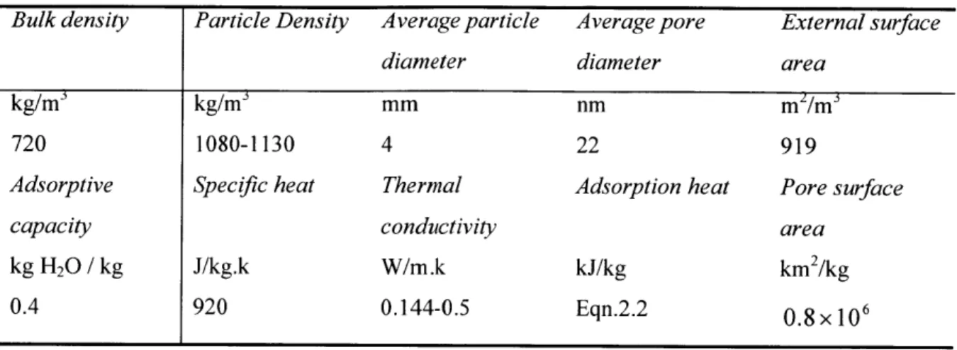
Table2.2 [5,17] gives the detailed physical properties of the Grade 01 regular density (RD) silica gel, which is used in this research.
Table 2.2 Material properties of GradeO1 regular density silica gel
Bulk density Particle Density Average particle Average pore External surface
diameter diameter area
kg/ms kg/m3 mm nm m /m3
720 1080-1130 4 22 919
Adsorptive Specific heat Thermal Adsorption heat Pore surface
capacity conductivity area
kg H20 / kg J/kg.k W/m.k kJ/kg km2/kg
CHAPTER 3
HEAT AND MASS TRANSFER BETWEEN DESICCANT PARTICLES AND MOIST AIR
Moisture transport is of particular interest in desiccant dehumidification. Heat transfer between moist air and desiccants also gains attention because temperature distribution greatly affects the mass transfer performance through desiccant isotherms. In this chapter, the heat and mass transfer between desiccant particles and a moist air stream is analyzed. Surface diffusion is found to dominate the mass transfer inside silica gel particles. Three models of transfer coefficients are presented and compared. The pseudo-gas-side controlled (PGC) model uses an empirical gas-side mass transfer coefficient to account for the diffusion resistance on the solid side. The semi-infinite model simplifies the solid side resistance calculation based on the semi-infinite body theory. The solid-side resistance (SSR) model solves the diffusion equation and is the most precise in terms of transfer coefficients. However, it makes analysis and calculation much more complicated.
3.1 Heat and Mass Transfer Process
Generally, the overall transport process between solid particles and moist air includes the following steps [19]:
1. Gas phase mass transfer of water vapor from the bulk of the moist air stream to the external surface of the solid particle. This is a convective mass transfer process.
2. Diffusion and phase change inside the solid particles in adsorption a) b) and desorption c) d). a) Diffusion of water vapor through the pores of the solid matrix. Both ordinary diffusion and
Knudsen diffusion are found. Which one dominates depends on the physical properties of the solid, especially the pore diameter.
b) Adsorption of water vapor on the surface of the solid matrix. Surface diffusion exists here. Phase change energy is released.
c) Desorption of water from the surface of the solid matrix. Phase change energy is needed.
d) Diffusion of water vapor through the pores of the solid matrix. Mass transports from the solid to air.
3. Water vapor mass transfer from the external surface of the solid to the bulk of the moist air stream.
1. Convective (and possibly radiative) heat transfer between moist air and the surface of the solid particles.
2. Conduction heat transfer within the solid particles.
The transfer process analysis shows that the overall transfer resistances consist of external convection and internal diffusion/conduction. Diffusion also has three mechanisms. Analysis is needed to
determine which diffusion mechanism dominates in silica gel particles and which resistance dominates the overall heat and mass transfer process. Diffusion coefficients are calculated and compared for the
former purpose. Heat and mass transfer Biot numbers are calculated for the second one.
3.1.1 Heat Transfer Biot Numbers
Heat transfer between desiccants and a moist air stream includes conductive heat transfer inside the particle and convective heat transfer outside the particle. Whether or not the conductive resistance can be ignored depends on its relative importance compared with the convective resistance. The heat transfer Biot number calculation will show this later.
The convective heat transfer resistance outside the particle
T.-T _1
R - air - - 3.1.1
q
k~A
The conductive heat transfer resistance inside the particle
Rcond ,
-
Tdd
3.1.2q
kdA
Where,
q heat flux J / s
Tair temperature of the moist air stream C
T, temperature of the air layer on the desiccant surface C
T
d temperature of the desiccant particles C
h
gas-side heat transfer coefficient W /m2Kkd thermal conductivity of desiccant W / m K
2
A heat transfer area m
The heat transfer Biot number is the ratio of internal conductive resistance to the external convective resistance. d Bh= kdA
he
d, 3.2 1 kd h AMills [20] gave the heat transfer correlation for flow of gases in a packed bed as followings:
Nu =(0.5Re1
2+0.2Re
2 /3)Pr1/3 k. h = Nu air'd,
Pr = 0.69, for air 3.3 Then, h d B,= hp " 3.4 kdRegular density GradeOl silica gel is used in this research. Its physical properties can be found in Table2.2. Particles with diameter of 4 mm and thermal conductivity of 0.5w /m K were used for the Biot number calculation.
Table3.1 Heat transfer Biot numbers for RD silica gel
Air stream velocity (m/s) Reynolds number Heat transfer Biot number RD silica gel d=4 mm, 0.5w/m.k 0.01 2 0.05 0.05 12 0.13 0.1 24 0.20 0.4 97 0.43 0.7 169 0.60 1.0 242 0.74 2.0 483 1.11 3.0 725 1.41
The usual engineering practice to completely ignore the inside conduction resistance is B, <0.1. It can be seen that the heat transfer Biot number is small and inside heat conduction resistance can be ignored when the air velocity is low. The inside conduction resistance cannot be ignored when the inside and outside resistances get closer and Biot number goes above 0.1. In this case, we still can simplify the
problem by assuming a thermally lumped particle with an empirically degraded overall heat transfer coefficient, which considers the solid side resistance. Actually, Pesaran [5] and San [21] found out that the effect on mass transfer of the temperature gradient inside silica gel was not significant. The
discrepancy was not obvious when a convective heat transfer coefficient alone was used. It means, it is practically acceptable to assume a thermally lumped particle and ignore the internal resistance.
3.1.2 Mass Transfer Mechanisms
Similar to heat transfer, mass transfer between silica gel particles and moist air includes external convection and internal diffusion. Diffusion involves more than one type of mechanism. Before we quantitatively compare internal and external mass transfer resistances, the mechanism of each type of diffusion resistance inside particles should be well understood.
Mass transfer inside the solid particle is complicated due to the porous nature of desiccants. Three mechanisms of diffusion can occur in porous solids [20]: ordinary diffusion, Knudsen diffusion, and surface diffusion. Ordinary diffusion of gaseous species, as described by Fick's law, dominates when the pores are large and the gas relatively dense. When the pores are small or the gas density is low, the molecules collide with pore walls more frequently than with each other. Then diffusion of molecules along the pore is described by the equations for free molecule flow and is called Knudsen diffusion. At intermediate pressures and pore sizes both types of collisions play an important role. Surface diffusion is the dominant mechanism of transport for the smallest pores, for which ordinary diffusion and Knudsen diffusion rates are very small.
For water vapor adsorbed in regular density silica gel with very small pores, it is necessary to estimate the magnitudes of these three diffusion mechanisms. Pesaran [5] researched solid-side mass transfer resistances, extensively surveyed the related references and summarized empirical formulas for different mechanisms.
Ordinary diffusion occurs when the molecules of the gas collide with each other more frequently than with pore walls of a porous medium. For porous materials like silica gel, the ordinary diffusion of the moist air into desiccants actually happens between the water vapor and the air trapped inside the pores. A useful formula [22] for the ordinary diffusion coefficient is:
DH
20air-1.7
0x
(T+ 273.15)1685
m2
s1


![Fig. 1.1 [1] shows how the condition of moist air changes in dehumidification on a psychrometric chart.](https://thumb-eu.123doks.com/thumbv2/123doknet/14676749.558166/20.918.145.418.268.561/fig-shows-condition-moist-changes-dehumidification-psychrometric-chart.webp)

![Fig. 2.2 Isotherms of various desiccants [29]](https://thumb-eu.123doks.com/thumbv2/123doknet/14676749.558166/32.918.128.777.107.455/fig-isotherms-various-desiccants.webp)