Publisher’s version / Version de l'éditeur:
Canadian Geotechnical Journal, 14, 2, pp. 266-271, 1977-05
READ THESE TERMS AND CONDITIONS CAREFULLY BEFORE USING THIS WEBSITE. https://nrc-publications.canada.ca/eng/copyright
Vous avez des questions? Nous pouvons vous aider. Pour communiquer directement avec un auteur, consultez la
première page de la revue dans laquelle son article a été publié afin de trouver ses coordonnées. Si vous n’arrivez pas à les repérer, communiquez avec nous à [email protected].
Questions? Contact the NRC Publications Archive team at
[email protected]. If you wish to email the authors directly, please see the first page of the publication for their contact information.
NRC Publications Archive
Archives des publications du CNRC
This publication could be one of several versions: author’s original, accepted manuscript or the publisher’s version. / La version de cette publication peut être l’une des suivantes : la version prépublication de l’auteur, la version acceptée du manuscrit ou la version de l’éditeur.
Access and use of this website and the material on it are subject to the Terms and Conditions set forth at
Design of a loading platen for testing ice and frozen soil
Law, K. T.
https://publications-cnrc.canada.ca/fra/droits
L’accès à ce site Web et l’utilisation de son contenu sont assujettis aux conditions présentées dans le site LISEZ CES CONDITIONS ATTENTIVEMENT AVANT D’UTILISER CE SITE WEB.
NRC Publications Record / Notice d'Archives des publications de CNRC:
https://nrc-publications.canada.ca/eng/view/object/?id=bd232906-25fb-427d-9af7-6bb1d8db69d5 https://publications-cnrc.canada.ca/fra/voir/objet/?id=bd232906-25fb-427d-9af7-6bb1d8db69d5
----
--
- --.-- S e r F-
,< 'TH1
N21dno.
716
dc . 2 National Research Conseil national Council Canada 'de recherches Canada
BLDG
I I I I - --
ANALYZED
DESIGN OF A LOADING PLATEN FOR
TESTING ICE AND FROZEN SOIL
by K.T. Law Ir
Reprinted from
Canadian Geotechnical Journal
Vol.
14, No. 2, May 1977, 6 ~ .DBR Paper No. 7 16
Division of Building Research
Price 10 cents
JUN
23
1877
CAN. GEOTECH. J. VOL. 14, 1977
Design of a loading platen for testing ice and frozen soil
K. T. LAW
Division ofBuilding Research, Geotechnical Section, National Research Council of Canada, Ottawa, Ont., Canada K I A OR6
Received July 21, 1976
Accepted February 8,1977
A critical review of the problems associated with the design of an ideal platen for uniaxial loading tests is presented. A method of design based on an analytical approach is then formu- lated. The method permits a liberal choice of material for constructing the platen, which consists mainly of a low modulus plug confined in a metallic ring. A finite element approach has been employed to substantiate the proposed method. Practical design aspects are also discussed.
On prksente une analyse critique des problbmes associes au dessin d'une plaque de t2te ideale pour des essais de chargement uniaxial. Une mkthode de calcul basie sur une approche analytique est formulee. La m6thode permet un vaste choix de materiaux pour la fabrication de la plaque qui consiste essentiellement en un element B faible module confine dans un anneau metallique. Une analyse par elements finis aete utilide pour confirmer la methode proposee. Les aspects pratiques du design sont tgalement discutes.
[Traduit par la revue]
Can. Geotech. J.. 14.266(1977)
Introduction
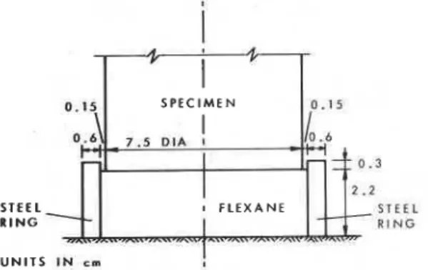
Law (1977) has made an analysis of the case of uniaxial loading on a cylindrical speci- men of frozen soil or ice using a compliant platen, consisting of a low modulus plug con- fined in a steel ring of diameter slightly larger than that of the specimen (Fig. 1). It was found that for a specimen length-to-diameter ratio equal to 2, satisfactory values of the
modulus of compression E, Poisson's ratio V,
and the strength of the material could be obtained if the axial strain was measured for the middle half of the specimen. The analysis, however, did show that significant nonuniform stress and strain still exist at the specimen-
platen interface. If higher quality testing is
required, if only a short specimen is available,
S T E E L R I N G
U N I T S I N cm !
FIG. 1. Sectional view of a typical compliant platen.
or if the material to be tested is anisotropic in behaviour, a better design of platen is needed.
Problems in Designing a Proper Platen
The performance of an ideal platen for testing a specimen should satisfy the following requirements.
( 1 ) The lateral deformation should be linear
with radius and should be equal to that of the specimen;
(2) The vertical compression should be uniform over the entire interface between the platen and the specimen.
( 3 ) The platen material should be stronger than the specimen.
For a very rigid platen, only requirements
(2) and (3) are fulfilled. In this case hardly
any lateral deformation occurs during the test. Nonuniform stress and strain are thus intro- duced. Attempts have been made to free the specimen ends using lubricants or deformable material interposed between the platen and the specimen. This approach does not, however, remove the inherent difficulties. A lubricant introduces problems in controlling the degree of restraint (Hawkes and Mellor 1970), while the deformable material generally violates all the requirements for an ideal platen. The fol- lowing example illustrates this point.
Consider a specimen of frozen Ottawa sand pressed between two sheets of hard rubber
known as flexane (Fig. 2 ) . The mechanical properties of the materials involved are given
I in Table 1. An analysis based on the finite
element method has- been carried out. The resulting deformation at the specimen-flexane interface due to a compressive load is shown in Fig. 3.
In Fig. 3a, the computed lateral displacement is compared with that of an ideal platen. At the periphery, the values of the computed and ideal displacements are so close that the pur- pose of freeing the specimen ends is apparently achieved. Upon further examination, however, the drawback of this platen becomes apparent. The lateral deformation vs. radius for the flexane is quite different from that of the ideal case. This difference, in fact, gives rise to a tensile radial stress near the periphery that is more than 25% of the compressive stress.
The calculated vertical deformations, shown in Fig. 3b, provide additional evidence that a deformable material inter~osed between the specimen and the machine platen does not satisfy requirement (2). Being weaker than the frozen soil, the flexane yields first. Thus, the alreadv nonuniform state of stress and strain is further aggravated.
An alternative approach involves the use of a process known as 'elastic matching'. The basic concept of this approach is to use a platen that would undergo the same radial
I
F R O Z E N O T T A W A S A N D( L E N G T H - D I A R A T I O = 2 )
I
F L E X A N E
uo.
U N I T S I N c m
FIG. 2. Cylindrical specimen pressed between de- formable sheets.
TABLE 1. Properties of materials used in this study Modulus of Poisson's
Material compression (Pa) ratio
Frozen Ottawa sand 1 x lo9 0.4
Ice 7 x lo9 0.3 Flexane 5 . 7 ~ lo7 0.49 Steel 2 . 0 ~ 10l1 0.27 TES 5 + z "J 2 1
2 :
,
L CY "7 8 - 0 - I L x 2 ", I +-
( 0 ) L A T E R A L D E F O R M A T I O N-
F L E X A N E S H E E T a 0 . 2 ~ . 4 0 . 6 0.8 1 .a R A D I A L D I S T A N C E / R A D I U S < 0 . 2 0 . 4 0 . 6 0 . 8 1.0 0 . 4 I I I I I 1 I I I ';-
0 . 6-
( b i A X I A L D E F O R M A T I O N I D E A L P L A T E N F L E X A N E S H E E TFro. 3. Deformation at specimen-platen interface.
strain as the specimen. This approach cannot be used, in general, because of the difficulty of finding an appropriate material, particularly for frozen soil whose modulus of elasticity may vary from specimen to specimen and is also dependent on the strain rate.
Another approach employs a dumbbell spec- imen for testing so that a uniform stress field is induced in the body of the specimen away from the platens. This approach, however, does not remove the possibility of stress concentra- tion near the ends (e.g. Paulding 1 9 6 6 ) . Further, the machining of special specimen shapes is quite an expensive undertaking and may not be feasible for quantity production. In the past, relatively few attempts have been made to examine critically the stress and strain induced in the platen; yet it is from these attempts that a rational design of platen may emerge. Many versions of designs are based on intuition (e.g. Kartashov et al. 1 9 7 0 ) or on the success of eliminating premature failure (Seldenrath and Gramberg 1 9 5 8 ) , although the need to look at the design of a platen in a more analytical manner is quite apparent.
Analytical Consideration
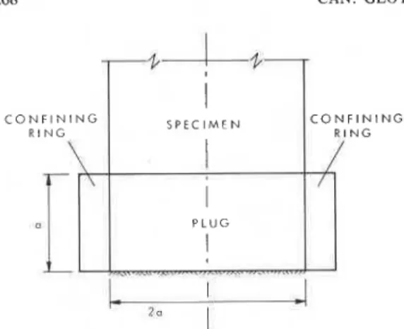
Consider a low modulus plug, of diameter
2a equal to that of the specimen, confined in
268 CAN. GEOTECH . J. VOL. 14, 1977 C O N F I N I N G SPECIMEN
I
C O N F I N I N G R I N G R I N GI
I
PLUGI
FIG. 4. Schematic view of the proposed platen.
uniform stress and strain at the interface can be written as
where a,, a,, are respectively the axial,
radial, and circumferential stresses in the platen; E,, E p are the moduli of compression
of specimen and plug respectively; and v,, v,
are Poisson's ratios for the specimen and the plug respectively. It should be noted that, while the axial pressure remains the same in the specimen and the platen, the radial and cir- cumferential stresses change drastically in crossing the interface.
For a length-to-diameter ratio for the plug equal to 1, the radial and circumferential stresses in the plug at the interface are approxi- mately equal (Filon 1902). Equation 1 can then be rewritten as
When the ring is absent
and [ l a ] becomes
This forms the basis for the 'elastic matching' approach.
To avoid the inherent problem of selecting a specific material for the platen in the 'elastic matching' approach, [ l a ] should be reex- amined. In this equation, the properties of the plug are related to both the properties of the
specimen and the values of ar generated in the
plug. By regulating a, one may, therefore, be
able to choose a convenient material and yet be able to maintain a state of uniform strain. The problem now becomes how to select a material and design the geometry of the con-
fining ring so that a, can be appropriately
generated.
Assuming no significant shear stresses are developed between the confining ring and the plug (this can be achieved by suitable lubrica-
tion), the radial displacement u, at the plug-
ring interface is given by (Wang 1953)
where E,, vc are the moduli of compression
and Poisson's ratio of the confining ring respec- tively; and b is the external radius of the ring. The unrestrained lateral surface deformation
of the specimen us can be written as
For perfect matching,
Substituting [la], [4], and [5] into [6] and re- arranging, one obtains an expression for b. Hence,
where
Equations 7 and 8 also define some physical limits on the choice of material constituting the platen. For a real and meaningful solution of [7], the following expressions have to be satisfied.
~ 9 1 1 - c ( 1
+
v,)>
o
Substituting [8] into the foregoing expres- sions gives
NOTES
These expressions can be interpreted in the following manner. Any material that is more compressible than the specimen can be em- ployed for making the plug; another material, whose rigidity exceeds a certain limit given by [lOa], can be used for constructing the ring. For ice and frozen soil, materials like flexane can be used for the plug and metals like steel or aluminum for the confining ring.
Example
It is necessary to design a platen for testing an ice specimen 15 cm long and 7.5 cm in diameter. The properties of the specimen are given in Table 1.
The designed platen, 3.75 cm thick (equal to the radius of the specimen1), consists of a flexane plug confined in a steel ring. The prop- erties of these two materials, also given in Table 1, can be shown to satisfy [9a] and [lOa]. Hence, based on these properties, C and b can be evaluated from [8] and [7] to give
C = 0.1115 and b = 4.21 cm, and thus, the basic design of the platen is achieved.
Numerical Verification
The finite element method (Zienkiewicz and Cheung 1967) was used to verify numerically the approach presented in the last section. The numerical modelling is illustrated in Fig. 5. The boundary conditions are:
( 1 ) the mid-plane is prescribed to move downwards in a plane with no lateral con- straint;
( 2 ) the base of the platen in contact with the machine is not permitted to move in any direction;
( 3 ) no lateral movement is allowed along the axis; and
( 4 ) a stiffness term S, consistent with the elastic behaviour of the ring, is applied to the nodes at the edge of the plug.
Consideration of slippage at the platen- sample interface is not necessary as it will be shown below that perfect matching is achieved at this interface.
The stiffness term S is defined as the radial force caused by unit displacement at the inner
'Because the plug deforms uniformly both in the axial and lateral directions at the interface, the length-to-diameter ratio of a single plug is equal to twice the ratio of the thickness to the diameter of the plug.
surface of the ring. For an axisymmetrical case, S can be derived by integrating a, from
[4] over the appropriate surface. Hence,
Zl o = o
where
zl
- z2 = d, the distance over which the contribution of the pressure is assumed to apply at a node (Fig. 5 ) ; and 0 = angular dis- tance. Upon simplification and rearranging, [ l 11 can be rewritten as[I21 S = 2?rCE,d
The example considered in the last section is used here for illustration. The results of computation are shown in Figs 6 and 7, in which the induced deformation and stress in the specimen at the interface are depicted.
The lateral and axial deformation shown in Fig. 6 conforms perfectly to that of an ideal case. The axial, radial, and circumferential
CAN. GEOTECH. J. VOL. 14, 1977 . " . L 0 0 2 0 4 0 . 6 0 . 8 1 . O R A D I A L D I S T A N C E / R A D I U S A X I A L COMPRESSION R A T I O A X I A L COMPRESSION AT PERIPHERY
i
0 0.5 1 . O 1 . 5 2 . 0 S A M P L E - P L A T E N A A A - A - 4 - A - A - A - A I N T E R F A C EFIG. 7. Computed stresses at specimen-platen in- terface. 2 0 6 +
'
0 . 4 - 0 . 2 0stresses are also remarkably uniform through- out the entire interface (Fig. 7 ) . The plot of radial and vertical deformation with distance from the interface as shown in Fig. 8 indicates that the distribution is quite linear except near the platen base. The numerical analysis, there- fore, substantiates the proposed' approach.
V E R T I C A L D E F O R M A T I O N /O V E R T I C A L C O M P R E S S I O N /'O O F S A M P L E
A
M ~ E ~ ~ L ~ E ~ O ~ ~ , A T I Q N / O LATEPAL D E L , J ~ A ~ - ' O ~ ~ n ; PEPIPHCRY-
L./O I b I l l I Il
R A D I A L D E F O R M A T I O N,
Discussion 0 . 2 0 4 0 . 6 0.8 1 .O L A T E I A L E X P A N S I O N U F S A M P L E R A D I A L D I S T A N C E R A D I U SFIG. 6. Computed axial and lateral deformations at specimen-platen interface.
",
0 . 8
P L A T E N B A S E
The design procedure presented in this re- port depends on a knowledge of the material behaviour prior to testing. A problem may arise, therefore, in obtaining such advance knowledge for the proper design of the platen. This problem is, nevertheless, inherent in any approach for the design of platens. To solve this problem tests with steel platen, for ex- ample, may be performed on some representa- tive samples. The accuracy of the mechanical properties thus observed would be within about 5% of the actual values (Law 1977). These properties can then be used for the proposed design method.
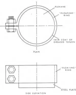
FIG. 8. Vertical and radial deformations within the platen. P L A N 1 F L E X A N E . F L O A T I N G ' R I N G P L A T C S I D E E L E V A T I O N
FIG. 9. Proposed platen design.
Friction that may develop at the ring-platen interface can be reduced in two ways. First, lubrication may be introduced by finely ma- chining the inside surface of the ring and then applying a thin permanent coat of Teflon to the surface. Additional lubrication can be ob- tained by properly greasing the Teflon surface.
NOTES 27 1
Second, to ensure that no axial load is being taken up by the ring it can be 'floated' on the plug. This can be accomplished by gluing the bottom face of the plug to a circular rigid steel plate of the same diameter as the plug (Fig. 9 ) . A method developed within the Geotech- nical Section, Division of Building Research, National Research Council of Canada, can be used to eliminate the problem caused by dif- ferential thermal contraction leading to a separation of the ring and the plug. It consists of using a split ring that has a device by which the ring can be tightened as necessary (Fig. 9 ) . It would be convenient if standard sets of rings of varying thickness were constructed. Once the preliminary properties of the spec- imen are determined, selection of the proper ring could be made from the available stock. It should be noted that the proposed design principle would be equally applicable to testing of other stiff materials such as rocks and concrete.
Summary
A rational method of designing platens for
uniaxial testing of cylindrical specimens is proposed using the concept of generating proper values of radial and circumferential stresses such that the resulting strain at the specimen-platen interface corresponds to an ideal case, in which the specimen deforms without any end restraining effect. The pro- posed platen consists mainly of a low-modulus plug confined in a smooth floating ring (Fig. 9 ) . The bottom face of the plug is glued to a rigid metal plate, both the plug and the plate being of the same diameter as the specimen.
This method permits a wide choice of mate- rials that can be used in constructing the platen. The procedure involved has been illustrated by an example which has been further used f6r verifying the proposed method with a finite element approach.
Acknowledgements
The author is grateful to his colleagues, T.H.W. Baker and J.H.L., Palmer, for their helpful discussions during the study. This paper is a contribution from the Division of Building Research, National Research Council of Canada, and is published with the approval of the Director of the Division.
FILON, L. N. G. 1902. On the elastic equilibriumof circular
cylinders under certaia practical systems of load. Philos. Trans. R. Soc. London, A198, pp. 147-233.
HAWKES, I. and MELLOR, M. 1970. Uniaxial testing in rock
mechanics laboratories. Eng. Geol. 4, pp. 177-285.
KARTASHOV, Yu. M., MAZUR-DZHURILOVSKII, Yu. D.,
and GROKHOL'SKII, A. A . 1970. Determination of the uniaxial compressive strengths of rocks. Sov. Min. Sci. No. 3, pp. 339-341.
LAW, K . T. 1977. Analysis of uniaxial loading on frozen soil and ice. (In preparation.).
PAULDING, B. W. 1966. Techniques used in studying the
fracture mechanicsof rock. Am. Soc. Test. Mater. Spec. Tech. Publ. No. 402, pp. 73-84.
SELDENRATH, TH. R. and GRAMBERG, J. 1958. Stress-
strain relations and breakage of rocks. In Conference on non-metallic brittle materials. Butterworth & Co. (Publishers) Ltd., London. pp. 79-105.
WANG, C. T . 1953. Applied elasticity. McGraw-Hill Pub-
lishing Co. Inc., New York, NY.
ZIENKIEWICZ, 0. C . and CHEUNG, Y. K. 1967. The finite element method in structural and continuum mechanics. McGraw-Hill Publishing Co. Inc., London.