Publisher’s version / Version de l'éditeur:
Vous avez des questions? Nous pouvons vous aider. Pour communiquer directement avec un auteur, consultez la première page de la revue dans laquelle son article a été publié afin de trouver ses coordonnées. Si vous n’arrivez pas à les repérer, communiquez avec nous à [email protected].
Questions? Contact the NRC Publications Archive team at
[email protected]. If you wish to email the authors directly, please see the first page of the publication for their contact information.
https://publications-cnrc.canada.ca/fra/droits
L’accès à ce site Web et l’utilisation de son contenu sont assujettis aux conditions présentées dans le site LISEZ CES CONDITIONS ATTENTIVEMENT AVANT D’UTILISER CE SITE WEB.
Canadian Journal of Civil Engineering, 7, 2, pp. 213-224, 1980-06
READ THESE TERMS AND CONDITIONS CAREFULLY BEFORE USING THIS WEBSITE.
https://nrc-publications.canada.ca/eng/copyright
NRC Publications Archive Record / Notice des Archives des publications du CNRC : https://nrc-publications.canada.ca/eng/view/object/?id=f871d374-8583-4d4a-ab9a-76a8e49c0ec0 https://publications-cnrc.canada.ca/fra/voir/objet/?id=f871d374-8583-4d4a-ab9a-76a8e49c0ec0
NRC Publications Archive
Archives des publications du CNRC
This publication could be one of several versions: author’s original, accepted manuscript or the publisher’s version. / La version de cette publication peut être l’une des suivantes : la version prépublication de l’auteur, la version acceptée du manuscrit ou la version de l’éditeur.
Access and use of this website and the material on it are subject to the Terms and Conditions set forth at
Dynamic tests on a steel-joist concrete-slab floor
Nat~onal Research Conseil national
1
*
Council Canada de recherches Canada1
8
DYNAMIC TESTS ON A STEEL-JOIST
:
CONCRETE-SLAB FLOOR
I
by J.H. Rainer
Reprinted from
Canadian Journal of Civil Engineering Vol. 7, No. 2, June 1980
pp. 213-224
DBR Paper No. 898
Division of Building Research
This publication is being distributed by the Division of Building Research of the National Research Council of Canada. It should not be reproduced in whole or in part without permis- sion of the original publisher. The Division would be glad to be of assistance in obtaining such permission.
Publications of the Division may be obtained by mailing the appropriate remittance (a Bank, Express, or Post Office Money Order, or a cheque, made payable to the Receiver General of Canada, credit NRC) to the National Research Council of Canada, Ottawa. KIA 0R6. Stamps are not acceptable. A list of all publications of the Division is available and may be obtained from the Publications Section, Division of Building Research, National Research Council of Canada, Ottawa.
Canadian Journal of
Revue canadienne
Civil Engineering
Published by
de
genie civll
Publiie par
THE NATIONAL RESEARCH COUNCIL OF CANADA LE CONSEIL NATIONAL DE RECHERCHES DU CANADA
Volume 7 Number 2 June 1980 Volume 7 numiro 2 June 1980
Dynamic tests on a steel-joist concrete-slab floor
.+!hiAi'YZED
J. H.RAINER
Noise and Vibration Section, Division of Building Research, National Research Council of Canada, Ottawa, Ont., Canada KIA OR6
Received September 4,1979
Revised manuscript accepted December 13, 1979
Dynamic propert~es have been determined for a composite steel-joist concrete-slab floor using heel impact and various shaker tests. The three modes located at 7.5, 12.4, and 18.7Hz exhibited increasing numbers of nodal lines parallel to the joists.
Application of vibration annoyance criteria for footsteps indicated that the floor was unsatis- factory. These criteria, presented in CSA Standard S I6.1, Appendix G. had been derived specifically for the lowest mode of the floor. Debtled evaluation of the experimental results. however, shows that mode 1 has satisfactory vibration characteristics as a result of its high damping value, whereas mode 2 is identified as unsatisfactory. This is corroborated by subjective assepsment. Vibration tests from walking steps were monitored and suitably filtered. Good agreement was found between the annoyance criteria derived from the heel impact test and those for "sustained vibrations" applied to the walking tests.
Based on the dynamic propert~es of the floor, an assessment is made regarding the effectiveness of partitions and truss bracing for reducing footstep vibrations.
L'auteur determine les proprietes dynamiques d'un plancher composite en dalles de beton sur solives d'acier au moyen de divers essais par coups de talon et vibrateurs. Les trois modes (7.5, 12.4 et 18.7 Hz) font apparaitre un nombre croissant de lignes nodales parallkles aux solives.
L'application de criteres de gbne due aux vibrations des chocs de pas indique que le plancher n'est pas satisfaisant. Ces critkres, presentes dans la norme ACNOR S16.1 annexe G, ont Bte calcules specifiquement pour le mode le plus bas du plancher. Une etude detaillee des resultats experimentaux montre cependant que le mode 1 a des caracteristiques vibratoires satisfaisantes en raison de sa valeur d'attenuation elevee, alors que le mode 2 est juge non satisfaisant. Une evaluation subjective confirme ces observations. Les essais de vibrations par chocs de pas sont enregistres et convenablement filtres. L'auteur trouve un bon accord entre Ies critkres de g6ne calcules apartirdes essais de coups de talon et ceux de vibrations soutenues appliquBes aux essais de marche.
A partir des proprietBs dynamiques du plancher, I'auteur evalue I'efficacite des cloisons et des membres raidisseurs rtduire les vibrations des chocs de pas.
Can. J. Civ. Eng., 7,213-224 (1980)
Introduction
The acceptability of floors from the point of view of vibration depends on three main factors: floor characteristics, type of excitation acting on the floor, and the acceptable vibration limits. Although the three factors interact in establishing design criteria, it is important that each be describable quantitatively and, above all, predictable to a sufficient degree of reliability.
This report concentrates on the first factor-the
determination and description of the dynamic characteristics of the floor. Most dynamic tests on floors have been performed by the heel impact test, where a sudden drop from raised heels imparts an impulsive force to the floor. As this test depends to some degree on the person performing the heel impact, it is not a well-controlled test and improve- ments in testing methods would be valuable.
A project was undertaken to determine the dy- namic properties of a particular floor by various test
03 15- 1468/80/0202 13- 12$01.00/0
214 CAN. J . CIV. ENG. VOL. 7, 1980
methods and thereby to assess the merits of alterna- tive procedures. The methods include the heel impact test, shaker tests with random, steady-state, and swept frequency excitation, and walking tests. The measured results are compared with predictions from simple formulae and vibration criteria for concrete- slab steel-joist floors. Certain conclusions are drawn regarding the effectiveness of partitions and truss bridging for this floor.
Recent work on dynamic testing of floors has been summarized by Allen and Rainer (1976), who also presented design criteria for satisfactory performance for residential and school occupancies. Two types of test, impact of an automobile tire and shaker excitation, have been described by Napier (1974). A comprehensive testing and evaluation project of long-span joist floors, including design criteria, has also been presented by Kawamura et al. (1977). As well, Wilson and Heidebrecht (1976) presented a critical review of design criteria with some results from measurements of long-span floors. Allen et al. (1979) have presented a selection of case histories and applications of vibration criteria to concrete structures. The design criteria described by Allen and Rainer (1976) have been incorporated in CSA
S16.1-1974, Appendix G, of the Canadian Steel
Standards (Canadian Standards Association 1974). A comparison of calculated versus measured floor properties was presented by Heins and Yoo (1975), and a series of measurements on different floor systems by Fahy and Westcott (1978).
Description of Floor
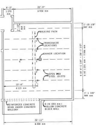
The floor under investigation is located on the
third storey of a 12 storey masonry building. A plan
view of the masonry wall layout and joist spacing is shown in Fig. 1. Heel impact tests were also carried out on an identical floor directly below. The slab and joists are of composite construction, with a specified 2+ in. (64 mm) concrete slab and 12 in. (305 mm) deep steel joists. It was observed, however, through two pipe openings in the floor, that the actual slab thickness was 33 in. (89 mm) at those points. No partitions, restraints, or services were in place at thetime of testing the third storey floor, but a few open-channel partition studs were being installed below the second storey floor when the heel impacts were performed there.
The following data for the floor are used: compo-
site area moment of inertia I, = 165 in.4 (0.0000687
m4); dead weight w = 11 .O lbflin. (1930 N/m) ; span
length = 26 ft 11 in. = 323 in. (8200 mm); Young's
modulus of steel E = 30 x lo6 psi (207 x lo5 MPa);
and concrete thickness t , = 2.5 in. (64 mm).
FIG. 1. Floor plan and instrumentation layout.
Testing and Analysis Procedure
Monitoring and Recording Equipment
The motions of the floor and the shaker armature were monitored by servo-drive accelerometers with a sensitivity of 5 V1g.l The transducers were placed at locations 1-5 (Fig. l), and for some tests an addi- tional accelerometer was placed at location 6 to aid in possible identification of various modes. All signals were recorded on a seven channel FM tape recorder for later analysis in the laboratory. Shaker Tests
All shaker tests utilized the same excitation point near location 3 (Fig. 1). The electrodynamic shaker, Model 113 Electro-Seis, has a maximum stroke of 6.25 in. (159 mm) peak-to-peak and a maximum sinusoidal force output of 30 lbf (133 N). Figure 2 shows the shaker and transducers on the test floor. Frequency Sweep
A swept frequency signal with a logarithmjc rate
of change was prerecorded on an F M tape recorder
and then played back to the shaker amplifier.
The
slow and medium sweep rates were 0.087 and 0.034
Hzls, respectively, at 12.5 Hz; and 0.1 14 and 0.44 Hzls, respectively, at 18.7 Hz. Shaker force output
'NOTE: g denotes gravitational acceleration; g = 32.2 ft/sZ
RAINER 215 .-. .. ...., ,. . 0 . 1 5
M
S H A K E R O U T P U T T R A N S D U C E R L O C A T I O N 5FIG. 2. View of shaker on test floor.
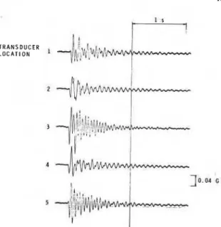
varied from 13.3 to 15.8 1bf (59 to 70 N). The resulting signals were analyzed for amplitude and phase, using a pair of wave analysers and a lock-in amplifier. The amplitudes of the signals at resonance frequencies 'were also examined directly (Fig. 3).
Random Excitation
An FM tape was prepared of band-limited white noise with f;equenc:es between 2 and 40 Hz. This signal was played into the power amplifier of the shaker, employing the voltage feedback option. This produced a fairly constant shaker force output that contrasted with a pronounced peak near the 4 Hz frequency in the absence of the feedback provision.
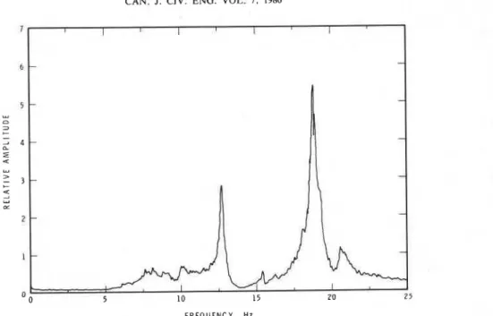
The recorded signals of floor response were played back through a real-time spectrum analyzer to obtain Fourier amplitude spectra. A typical result for location 3 is shown in Fig. 4. Relative phase was determined from spectra of sums and differences of pairs of signals.
Discrete Frequency
Constant-amplitude sinusoidal signals generated by a remotely programmable frequency synthesizer were fed to the power amplifier of the shaker. The discrete frequencies were selected on the basis of the anticipated response, as judged from the signal amplitude of the previous frequency increment. As
FIG. 3. Floor acceleration response due to swept-frequency shaker excitation at 12.5 Hz, storey 3.
the signal increased, the frequency increments were decreased so as to achieve a sufficient density of points to define the frequency-response curve adequately. Duration of each frequency increment was approximately 30 s. Shaker force varied from
20.2 to 24.0 lbf (90 to 107 N). The results for the discrete frequency test are shown by the plotting points in Fig< 5, along with the response curve from the slow frequency sweep.
Heel Impact
The heel impact test is performed as follows. A
170 lb (77 kg) man wearing street shoes with hard rubber heels supports his weight on the balls of his feet, heels raised approximately 2) in. (64 mm). The full body weight is then suddenly transferred to the heel, resulting in an impact on the floor.
The recorded signals were played back using various combinations of high-pass and low-pass filters having 48 dB per octave attenuation. Typical filtered and unfiltered signals resulting from heel impacts are presented in Figs. 6 and 7.
Walking Test
Vibrations resulting from a brisk walk across the floor and a return along the line formed by the trans- ducer stations were monitored and recorded. On playback they were filtered at frequencies similar to those of the heel\impact signals in order to resolve
CAN. J . CIV. ENG. VOL. 7, 1980
F R E Q U E N C Y . HZ
FIG. 4. Fourier amplitude.spectrum of floor acceleration response due to random excitation at location 1, storey 3.
Z 0
-
D A T A P O I N T F O R D I S C R E T E + 0 . 4 F R E Q U E N C Y R E S P O N S E J O I N E D B Y S T R A I G H T L I N E S L., 2 L.,-
R E S P O N S E T O S W E P T 0 U F R E Q U E N C Y E X C I T A T I O N 4 0 . 3 Ln Ez
0 . 2 Z,.,
3 0 e , 0 . 1 - b.. .% u E-
0 3 . 0 5 . 5 8 . 0 10.5 1 3 . 0 1 5 . 5 1 8 . 0 2 0 . 5 2 3 . 0 2 2 . 5 F R E O U E N C Y . H zFIG. 5. Slow sweep and discrete frequency acceleration response for location 3, storey 3.
the total motion into the individual modal contribu- tions.
Results
The results of the analysis of the various test methods are grouped as follows.
Natural Frequencies
The natural floor frequencies obtained by the various methods are given in Table 1. The lowest frequency is difficult to identify from the shaker tests and better ways of positively identifying this mode would be valuable. Although the heel impact indicates a frequency of about 7.5 Hz for the third storey floor, it is not corroborated by the other test methods because the spectra from the random exci- tation and the swept frequency tests show other
potential resonance peaks with similar amplitudes. Slight differences in natural frequency are evident
in the various methods of analysis. In particular, the
'
natural frequencies from the sweep tests are some- what higher than those from the other methods. Nevertheless, agreement is well within the range required for practical application to most floor vibration problems.
Mode Shapes
Mode shapes obtained from the various methods are shown in Fig. 8. The amplitudes for modes 2 and
3 are normalized to the amplitude at location 3. For mode 1 only the amplitudes from the random results and heel impact are plotted since they were thought to be reliable.
RAINER 217
FIG. 6. Floor acceleration response due to heel impact at location 3, storey 3.
It may be observed that all testing methods provide a sufficiently accurate description of shape for modes 2 and 3. It is probable that the same would also be true for mode 1 if its response could have been made more prominent.
Damping
Damping is expressed as a ratio of critical modal damping and was calculated from the results as follows.
Heel impact :
[l] 6 = (112nn) ln (x,/xn)
where xo and xn are the amplitudes of the zero and n successive cycles of the modal impulse decay curve. Except for mode 1, two sets of damping values were computed using the first 10 and subsequent 10 cycles.
Swept frequency, discrete frequency, and random vibrations :
where Af is the width of the response curve of a particular mode at 0.707 times its height, and fo is the modal frequency. The results are shown in Table 1, which indicates that relatively large varia- tions in damping are found, depending on the testing and analysis method used.
Amplitude of Response to Heel Impact
For individual modes the amplitude of response to heel impact is determined at the point of impact and where that mode has the largest modal ampli- tude. The results for the floors on storeys 2 and 3 are presented in Table 2.
Walking Vibrations
The walking vibrations monitored at five positions across the floor are shown in Fig. 9, where it may be seen that the amplitude and frequency content of the floor response are quite different at the various monitoring and walker locations. This can be as- cribed to the contributions of the individual modes of vibration to over-all response. The effect is accentuated in Fig. 10, where the signals were filtered to isolate the contributions of modes 1,2, and 3.
It may be observed that in the first mode little oscillatory motion follows the initial response to each step. It can therefore be deduced that this mode is highly damped. Peak amplitudes are 0.6% of g . On the other hand, the response for mode 2 exhibits a sustained oscillatory motion consistent with ,the relatively low modal damping- ratio for that mode. From some other tests it was also observed that an excitation at location 2 produces
a
response at loca- tion 4 of almost the same magnitude, 1.8% of g peak acceleration.Another characteristic emerges from the filtered
T R A N S D U C E R L O C A T I O N 1
- I
FIG. 7. Filtered floor response due to heel impact, storey 3. ( a ) Mode 1 : impact at location 3 (filtered at 9.5 Hz low pass). (b) Mode 2: impact at location 2 (filtered at 12 Hz high pass, 15 Hz low pass). (c) Mode 3: impact at location 3 (filtered at 15 Hz high pass. 25 Hz low pass).
218 CAN. J. CIV. ENG. VOL. 7, 1980
TABLE 1. Resonance frequencies and damping ratios obtained by various methods
Resonance frequency (Hz) Damping ratio, 6(% of critical)* Method Mode 1 Mode 2 Mode 3 Mode 1 Mode 2 Mode 3
Slow sweep Frequency-amplitude plot
Time trace maximum
- 12.8 18.7 -
-
-
response amplitude
Medium sweep
Frequency-amplitude plot 13.2 19.1 -
-
-
Time trace maximum
response amplitude -
Discrete frequency
- 12.4 18.7
-
Frequency-amplitude plot
- 12.8 18.5
-
-
Time trace maximum
Fourier spectrum Third storey Random vibrations 0.80 0.90 7.5; (lo?) 12.6 18.9 - 0.80 0.80 Heel impactt 7.5 12.5 18.7 11::: 2.2 [1.9] 2.0 [1.51 1.9 [1.75] 2.1 [1.6] Second storey 9.5 12.5 18.7 6.0 2.2 [1.5] 2.0 [1.5] 11.7 2.1
'Multiple values represent range from various determinations.
?Damping calculated from first three cycles for mode 1, first 10 cycles for modes 2 and 3. Damping values for subsequent 10 cycles for modes 2 and 3 are given in brackets.
walking vibrations of Fig. 10: as the walker proceeds across-the floor various amplitudes of vibration of the component modes are excited. For example, at location 2 the amplitudes of vibration in mode 2 are
small when the walker is at location 5, but they
become large when the walker is near location 4. The vibrations decrease when the walker is near location 3 and then increase again for walking near location 2. From the filtered analysis of the floor vibration signals it may be seen that the response of the floor can be correlated with the position of the walker and with the amplitude of the mode shape for the particular mode under consideration. Again referring to Fig. 10 and making reference to the shape of mode 2 in Fig. 8, one can verify that the largest response to walking is obtained when the excitation occurs at a point that corresponds to the largest modal ampli- tudes, i.e., at locations 2 and 4. When the excitation occurs at such a position, all other locations respond at vibration amplitudes and phase at approximately the same ratio as the modal amplitudes and phase for the natural mode under consideration. Similar direct comparisons can be made for modes 1 and 3 in
- Fig. 8 and the filtered responses shown in Fig. 10.
Evaluation of Floor Vibration Acceptability
The floors were tested before any partitions, services, or furnishings were installed. Evaluations of "satisfactory" or "unsatisfactory" therefore apply to that state of construction and not to performance in the completed stage. The presence of partitions and furnishings will change the dynamic charac- teristics of the floor and reduce the amplitude of vibrations to a fraction of that in the bare floor. Nevertheless, the study of bare floors such as those considered yields useful data on dynamic properties of similar types of construction for which no parti- tions or furnishings are intended. It also provides an opportunity to compare the dynamic performance of the floor with existing design criteria.
Comparison of Measured and Calculated Parameters In assessing present design methods for satis- factory floor behaviour it is of interest to compare predicted floor properties with those measured at the site.
Mode 1
The predicted natural frequency for mode 1 (Allen and Rainer 1976) is
RAINER 219
DISCRETE FREQUENCY
0 HEEL I M P A C T 0 RANDOM V I B R A T I O N S n M E D I U M SWEEP RATE 0 SLOW SWEEP RATE
-
10L O C A T I O N : 1 2 3 4 5
FIG. 8. Mode shapes for test floor, storey 3. (a) Mode 1
1 (7.6 Hz). ( 6 ) Mode 2 (12.5 Hz). (c) Mode 3 (18.7 Hz).
1 where E = modulus of elasticity of steel (psi); I =
moment of inertia of transformed section (in.4);
w = dead weight (lblin.); and L = span (in.).' The
predicted initial amplitude, for normal concrete and
with span length L and concrete thickness t, in
inches, is
[4] a, = 350f/Ltc(l
+
t,) = 9.4% of gIf the measured concrete thickness of 33 in. (89 mm) is used, the natural frequency is, by calculation, 5.3 Hz. This is even lower than the initially predicted
TABLE 2. Measured peak accelerations from heel impact test - - Heel Natural impact frequency location Storey (Hz) Initial amplitude a0 (% of g) 4.9 5 . 8 7 . 4 6 . 3 6 . 0 6 . 2 7 . 6 6 . 0
6.3 Hz and considerably below the measured 7.5 Hz.
For calculation of initial amplitude a,, using
t, = 3.5 in. (89 mm) instead of 2.5 in. (64 mm) and
the measured frequency of 7.5 Hz, one obtains
a, = 6.2% of g. This compares favourably with the
measured values of 6.0 and 6.3% of g.
Mode 2
Although the frequency of the second mode is not predictable by the simple formula for frequency5 the maximum response to heel impact can be assessed by slightly modifying the formula for a,. It should be noted that the frequency of mode 2 is above the suggested 10 Hz upper limit of applicability for the design formulae of Allen and Rainer (1976). This limit is not, however, a very precise one and in view of the relatively large span it is thought that the sug- gested 10 Hz upper limit can be extended somewhat. In calculating the initial amplitude a, for mode 2, the following adjustments were carried out in the
determination of the effective mass M. The floor
vibration criteria presented by Allen and Rainer (1976) and CSA Standard S16.1-1974 took the effec- tive participating width of a vibrating panel t o be 60tc. This arises from an assumed deformation pat- tern of one half sine wave in the direction normal to the joists and is a simplification of the procedure employed by Galambos (1973) for, determining the number of joists that participate in establishing the effective vibrating mass. For mode 2 shown in Fig. 8 the width that approximates one half sine wave is 14 ft (4260 mm), whereas 60tc gives 17.5 ft (5334 mm). Since for mode 2, however, an impact has to accelerate the equally large positive and negative lobes of the mode shape, the effective width has to be doubled to 28 ft (8320 mm). Following the procedure
outlined by Allen and Rainer (1976), the mass M
becomes, for span length L in feet, t, in inches, and
g = 32.2 ft/s2,
'The formulae for f and a,, depend on the dimensions used. M = 0.4L(28.0)(12tc
+
12)/g 1b.s2/ftOnly the versions using the Imperial units are given here. See
220 CAN. J . CIV. ENG. VOL. 7. 1980
T R A N S D U C E R
L 0 C A T I 0 N !
kw'i&vvv$dvA
~ v ~ / L ~ p i ~ ' f l '
? ~ f l q ~ { ~ ! ~ ~ , J \ ~ @ $ ~ 9 ~ ~ ~ h ~ ~ w A w
I !
4W A L K E R A T L O C A T I O N : 5 4 3 2 1
FIG. 9. Acceleration response due to walking, storey 3.
W A L K E R A T L O C A T I O N : 5 4 3 2 1 ! I T R A N S D U C E R I s C L O C A T I O N 2
r
~
~
w
\
n
4
r
\
j
v
n
~
2 -\ V M O D E 2 . . . 1 0.050 G3
M O D E 3'
i - . - . --- -+-~-- ~-FIG. 10. Filtered acceleration response due to walking for modes 1, 2, and 3, storey 3.
12.4 Hz, substitution in unacceptable in relation to the criteria, and vice r
gives a calculated initial amplitude a, of 6.3% of g.
This compares favourably with the measured values of 6.2 and 7.6% of g.
Assessment of Acceptability from Heel Impact Tests
The annoyance criteria for the heel impact test (Allen and Rainer 1976; Canadian Standards Association 1974) are reproduced in Fig. 1 1. Thereon are plotted in open symbols the acceptability limits for the various cases, and in closed symbols the measured or calculated values. When the open symbol falls above the closed symbol, the floor is
versa.
For mode 1 the predicted value a, = 9.4% of g,
based on design parameters, plots as the black circle in Fig. 11. The corresponding acceptable criterion is given by the open circle, based on the estimated damping being 3% of critical for a bare floor. On the basis of these criteria, the floor would be considered unsatisfactory. With measured parameters f =
7.5 Hz and t , = 3.5 in. (89 mm), a , becomes 6.2% of g and is plotted in Fig. 11 by the square symbol. Again the floor is unsatisfactory. If, however, a measured damping of 10-12% is used, then the floor satisfies the annoyance criteria, as indicated by the triangular symbols in Fig. 11. In the design stage the
RAINER 22 1
I
I I /-
/ .DAMPING R A T I O 3 %---
C R l T E R l A fOR - ( E S T I M A T E D ) D A M P I N G R A T I O 2 % 0 D E S I G N C A L C U L A T I O N S 0 D E S I G N C A L C U L A T I O N S M O D I F I E D W I T H M E A S U R E D PARAMETERS L P R E D I C T E D OR M E A S U R E D F R E Q U E N C Y . HzFIG. 11. Annoyance criteria for floor vibrations based on heel impact tests (Canadian Standards Association 1974). Data points for storey 3.
floor would therefore be considered unsatisfactory, whereas an evaluation of the actual floor, using measured parameters, shows that mode 1 satisfies the vibration criteria of CSA Standard S16.1-1974.
For mode 2, assuming the validity of extending beyond the suggested frequency limit of 10 Hz for the design criteria, one can enter the design criteria with a, = 6.3% of g, determined above, and the measured damping value of 2%. With the square plotting point for mode 2 in Fig. 11 located above the acceptable criterion points the bare floor
,
response is unsatisfactory. This agrees with the observations of two people seated on hard chairs at a location close to the maximum modal amplitude for mode 2 while a walker paces the floor.4
Assessment of Acceptability from Walking Vibrations Sustained vibration criteria "for 10 to 30 cycles" (Allen and Rainer 1976; Canadian Standards Association 1974) are reproduced in Fig. 12 and applied to the various modal vibrations shown in Fig. 10. The latter were obtained by filtering the total walking vibrations presented in Fig. 9.
The separate treatment, of such vibration com- ponents can be justified by noting that the major contributions from modes 2 and 3 are separated in time. The dominant levels of vibration trains thus do not occur simultaneously; different modes are excited when a walker takes different positions on the floor. Furthermore, mode 1 (being so highly damped)
contributes only isolated pulses to the total vibration signal. Such a separation procedure would not be appropriate if closely spaced modal frequencies and simultaneous high modal vibrations were to occur.
The observed vibration amplitudes for modes 1,2, and 3 are plotted in Fig. 12, showing that mode 2 substantially exceeds the sustained vibration cri- terion given by the solid line. Modes 1 and 3, on the other hand, fall near or below the acceptable limit. This agrees qualitatively with the measured results of the heel impact tests in Fig. 11 and with the subjective evaluation of floor vibration annoyance.
5 . 0 WALKING TEST 0 LIMIT OF ACCEPTABILITY CRITERION FOR CONTINUOUS VIBRATIONS AVERAGE AMPLITUDE OF Z RESPONSE
::
0 . 5 4 Y 9 0 % 8 H O U R S2
> 4 0 . 1 1 2 4 6 10 20 FREQUENCY. HzFIG. 12. Annoyance criteria for floor vibrations based on sustained vibrations (Canadian Standards Association 1974). Data points for storey 3.
222 CAN. J . CIV. Eb
This agreement is significant since it demonstrates the correspondence between the two criteria for a limited range of floor properties. It will be recalled that the heel impact criteria were derived from com- parisons between heel impact response and a sub- jective rating for walking vibrations of "satisfactory"
or "unsatisfactory." There was no direct link between the two types of loading. It must be em- phasized that the walking vibrations are of direct interest, whereas the heel impact test is only an indirect means of assessing floor response.
Discussion of Results
Test Methods
The various test methods can be compared on the basis of the degree of complexity of each test, ease of analysing the results, and amount and reliability of information obtained. Some aspects often depend on the personal preference of the person doing the test or on the availability of equipment.
In comparing the determinations of natural fre- quency (Table I), mode shapes (Fig. 8), and ampli- tude of response all test methods agreed very closely and no one method could be given any obvious preference. The values for damping, however, showed substantial variations. If one assumes that internal damping mechanisms cause a decay of vibration amplitudes, it can be argued that the impulse decay curve should give the most realistic quantitative indicator of modal damping. All other methods provide damping values by indirect means and thus can depend on the manner in which the test and analysis are carried out. For example, the sweep rate needs to be very slow so that a sufficiently high resonance peak can be obtained; the frequency increment for the steady-state test needs to be fine enough to define both the peak and the width of the resonance peak adequately; and for the random force shaker test the number of time averages and the "randomness" of the excitation are important in obtaining a sufficiently stationary response. All the tests require fairly complex analysis equipment and due attention to calibration and use. They also have some inherent limitations in accuracy.
As far as amplitude of response is concerned, the heel impact test overcomes the problem of the low response level of the highly damped first mode since the initial impact response is not highly dependent on damping. On the other hand, the floor response to random or steady-state excitation is inversely propor- tional to damping, and consequently mode 1 can barely be identified in the spectra resulting from random or swept-frequency excitation.
The response from a heel impact test needs to be
TG. VOL. 7, 1980
suitably processed by filtering so that the various component frequencies can be isolated. Otherwise, irregular decay curves or beats appear and their rational interpretation in terms of damping becomes difficult or even impossible.
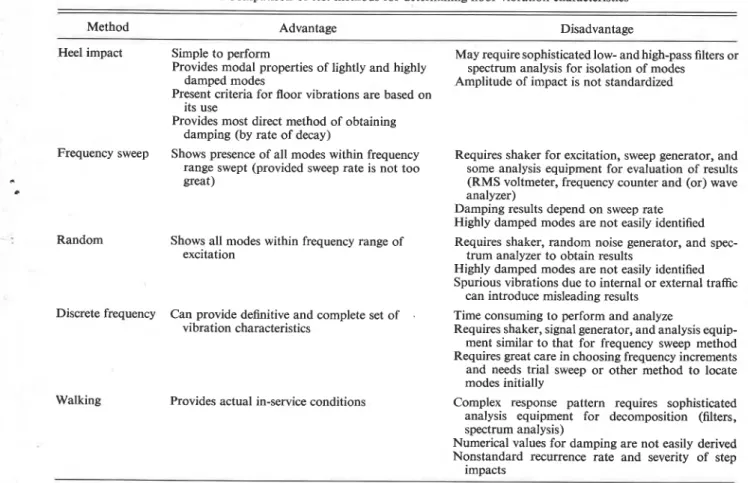
Some of the advantages and disadvantages of the various testing methods have been summarized in Table 3. On the basis of its simplicity and the com- pleteness of the information that can be obtained, the heel impact appears to be the most useful test method. If its one major disadvantage could be over-
come, namely the lack of control on the magnitude
.
of impulse, it would constitute a most completetesting method for dynamic floor properties.
Floor Characteristics
The dynamic floor properties determined for this specimen in the form of mode shapes, frequencies, and damping ratios provide some interesting results. Modes 1, 2, and 3 are all flexural modes in which, longitudinally, the joists assume the typical half sine wave shape of the fundamental mode of a simply supported beam; laterally, the relative phase of adjacent joists provides for distinct mode shapes and natural frequencies. These different modes are a function of the lateral stiffness of the slab and prob- ably also depend on the lateral dimension of the floor. Another surprising result is that the critical damping ratio of mode 1 was substantially higher than those for modes 2 and 3. Modes 2 and 3, there- fore, do not damp out quickly and tend to be a source of annoyance. The reasons for the high damping in mode 1 are not readily apparent. It may be that the secondary displacements or restraints at the wall supports provide a source of frictional energy dissipation primarily in the displacement pattern of mode 1. From Table 2 it may be seen that
for modes 2 and 3 the damping ratios computed from ,
the second set of 10 cycles are slightly lower than * those computed from the first 10 cycles. This sug- gests some amplitude-dependent damping mech-
anism. b
The corrected, calculated fundamental frequency of 5.3 Hz is considerably below the 7.5 Hz measured for mode 1. It would appear that various unknown sources of stiffness act on the floor and contribute to a raising of the natural frequency. Among these may be end constraints by the walls (both in-plane and end moments), two-way plate action by the slab, higher concrete strength or modulus, and possible dimensional variations of joists and slab.
The predicted initial acceleration a, (Allen and Rainer 1976) is substantially higher than that measured from heel impact. By using actual mea- sured floor properties in [4] the agreement between
RAINER
Shows all modes within frequency range of excitation
TABLE 3. Comparison of test methods for determining floor vibration characteristics
Method Advantage Disadvantage
Heel impact Simple to perform May require sophisticated low- and high-pass filters or Provides modal properties of lightly and highly spectrum analysis for isolation of modes
damped modes Amplitude of impact is not standardized Present criteria for floor vibrations are based on
its use
Provides most direct method of obtaining damping (by rate of decay)
Frequency sweep Shows presence of all modes within frequency Requires shaker for excitation, sweep generator, and range swept (provided sweep rate is not too some analysis equipment for evaluation of results great) (RMS voltmeter, frequency counter and (or) wave
analyzer)
Damping results depend on sweep rate Highly damped modes are not easily identified Random Requires shaker, random noise generator, and spec-
trum analyzer to obtain results
Highly damped modes are not easily identified Spurious vibrations due to internal or external traffic
can introduce misleading results Discrete frequency Can provide definitive and complete set of . Time consuming to perform and analyze
vibration characteristics Requires shaker, signal generator, and analysis equip- ment similar to that for frequency sweep method Requires great care in choosing frequency increments and needs trial sweep or other method to locate modes initially
Walking Complex response pattern requires sophisticated analysis equipment for decomposition (filters, spectrum analysis)
Numerical values for damping are not easily derived Nonstandard recurrence rate and severity of step
impacts Provides actual in-service conditions
the calculated value of a, and the measured response from heel impact is quite close. This is an indication that the designer's inability to specify actual condi- tions for the floor and to control construction prac- tices can introduce substantial discrepancies between predicted and observed results.
I
An attempt to apply the formula for calculating the initial acceleration for a, for mode 2 gives reasonable results, although the frequency for mode 1
2 slightly exceeds the recommended range for the applicability of the formula. The formula for cal- culating the fundamental frequency, however, ap- plies only to mode 1 and is not applicable to higher modes.
Implication for Remedial Measures
Occasionally a floor vibrates too much to suit the intended occupancy. This may be because the designer was unable to predict the actual per- formance of a floor or because the vibration criteria became more stringent as a result of change in use or occupancy of the floor space. Reduction of floor vibration levels may require remedial measures such
as resonance dampers, damper posts (Allen 1974), or partitions.
Detailed study of mode shapes of the floor and its dynamic response to walking indicates that a single partition located on the nodal line of mode 2 (i.e., where the mode shape intersects the equilibrium plane) would have no effect in reducing the vibration amplitudes contributed by that mode. As mode 2 is largely responsible for the annoying vibration levels, subjective evaluation of the floor would thus not be improved. The same partition, however, installed near one or both of the maximum modal amplitudes of mode 2 (Fig. 8), could be expected to have a beneficial effect. Similarly, a partition normal to the joists could be expected to reduce vibration amplitudes for modes 2 and 3 because of added con- straints. Thus, the effectiveness of a partition in reducing floor vibrations depends on its location
and orientation.
By similar arguments one may conclude that, for this floor, truss bridging applied normal to the joists should improve vibration performance. Such bridg- ing would increase the lateral floor stiffness and raise
224 CAN. J. CIV. ENG. VOL. 7, 1980
the natural frequency of mode 2 while simultan- eously reducing the amplitudes of the modal vibra- tion. The same would apply to mode 3. Both trends are beneficial when viewed in relation to the annoy- ance criteria of Figs. 11 and 12.
Conclusions
(1) Vibration tests on a steel-joist concrete-slab floor have shown that of the test methods applied the heel impact test provides the most complete set of vibration characteristics. In particular, damping values are thought to be the most reliable. For highly damped modes the heel impact test was the only one from which it was possible to obtain damping values. The only drawback of the heel impact appears to be the noncalibrated amplitude of the impulse.
(2) The tested floor exhibited three dominant mode shapes at frequencies of 7.5, 12.5, and 18.7 Hz, designated as modes 1, 2, and 3. The respective mode shapes are characterized by increasing numbers of nodal lines parallel to the joists, indicating that these modes are influenced greatly by the lateral stiffness of the slab.
(3) The modal damping ratio of mode 1 was between 9 and I l ? of critical. whereas those for modes 2 and 3 were gpproximately 2% of critical.
(4) For mode 1 the predicted natural frequency and the initial acceleration amplitude to a simulated heel impact agree reasonably well with the respective measured quantities when actual measured values of floor properties are employed. The recommended damping value for design is substantially lower, however, than that measured. With appropriate adjustments, application of the formula for initial amplitude a, to mode 2 also shows good agreement with measurements.
(5) Application of the floor vibration criteria of CSA S16.1-1974 indicates that a bare floor vibrating in the assumed fundamental mode shape is not satisfactory for ordinary quiet occupancy. Detailed consideration of the properties of modes 1 and 2 shows that the vibrations of mode 1 will probably not be annoying, but that those of mode 2 would be. The criteria thus identify the floor as unsatisfactory, but fail to identify the nature of the problem correctly.
( 6 ) For this floor the acceptability criteria for
walking vibrations based on the heel impact test agree qualitatively, and to some degree quantita- tively, with the annoyance criteria for sustained vibrations, both criteria being contained in CSA S16.1-1974, Appendix G.
(7) The dynamic measurements carried out on the tested floor permit the conclusion that the usefulness of a partition in reducing vibrations from walkers depends on its location and orientation. For the floor investigated a partition in the middle of the room and parallel to the joists would be ineffective. On the other hand, a partition near the quarter points, or one that is oriented normal to the joists, would be beneficial. Similarly, truss bridging between the joists would be useful in improving vibration acceptability of this floor.
r
Acknowledgements
.
Experiments were carried out while the building was under construction and the cooperation of the ,
following is gratefully acknowledged : J. Richard, Project Engineer; P. Martineau, Architect; and Hambro Structural Systems. The tests and data analysis were carried out with the assistance of R. G. Diment, Division of Building Research, National Research Council of Canada.
This paper is a contribution from the Division of Building Research, National Research Council of Canada, and is published with the approval of the Director of the Division.
ALLEN, D. L. 1974. Vibrational behaviour of long-span floor slabs. Canadian Journal of Civil Engineering, 1, pp. 108-115. ALLEN, D. E., and RAINER, J. H. 1976. Vibration criteria for
long-span floors. Canadian Journal of Civil Engineering, 3, '
pp. 165-173.
ALLEN, D. E., RAINER, J. H., and PERNICA, G. 1979. Vibration criteria for long-span concrete floors. In Vibrations of concrete structures. American Concrete Institute, Detroit, MI, Publi- cation SP-60, pp. 67-78.
CANADIAN STANDARDS ASSOCIATION. 1974. Guide for floor vi- brations, Appendix G. In Steel structures for building -limit
states design. Canadian Standards Association, Rexdale, Ont., CSA Standard S16.1-1974.
FAHY, F. J., and WESTCOTT, M. E. 1978. Measurement of floor mobility at low frequencies in some buildings with long floor spans. Journal of Sound and Vibration, 57, pp. 101-129. GALAMBOS, T. V. 1973. Vibration of steel joist - concrete slab
floors. Steel Joist Institute, Arlington, VA, Technical Digest No. 5.
HEINS, C. P., JR., and Yoo, C. H. 1975. Dynamic response of a building floor system. Building Science, 10, pp. 143-153. KAWAMURA, M., e t al. 1977. The vibration property of large-
span floor girders. (In Japanese.) Edited by Building Research Institute, Shinjuka, Tokyo. Kenchiku Gijutsu, No. 310, pp.
141-153.
NAPIER, J. C. 1974. Comparison of two excitation methods for determining "feelable" dynamic response in buildings. Pro- ceedings of Inter-Noise 74, Washington, DC, pp. 645-648. WILSON, J., and HEIDEBRECHT, A. 1976. Vibration characteris-
tics of long span floor systems. Report prepared for Canadian Steel Industries Construction Council, McMaster University, Hamilton, Ont. 97 p. plus Appendices.