Publisher’s version / Version de l'éditeur:
Applied Acoustics, 15, 4, pp. 307-314, 1982-07
READ THESE TERMS AND CONDITIONS CAREFULLY BEFORE USING THIS WEBSITE. https://nrc-publications.canada.ca/eng/copyright
Vous avez des questions? Nous pouvons vous aider. Pour communiquer directement avec un auteur, consultez la
première page de la revue dans laquelle son article a été publié afin de trouver ses coordonnées. Si vous n’arrivez pas à les repérer, communiquez avec nous à [email protected].
Questions? Contact the NRC Publications Archive team at
[email protected]. If you wish to email the authors directly, please see the first page of the publication for their contact information.
NRC Publications Archive
Archives des publications du CNRC
This publication could be one of several versions: author’s original, accepted manuscript or the publisher’s version. / La version de cette publication peut être l’une des suivantes : la version prépublication de l’auteur, la version acceptée du manuscrit ou la version de l’éditeur.
Access and use of this website and the material on it are subject to the Terms and Conditions set forth at
Influence of specimen frame on sound transmission loss measurement
Warnock, A. C. C.
https://publications-cnrc.canada.ca/fra/droits
L’accès à ce site Web et l’utilisation de son contenu sont assujettis aux conditions présentées dans le site LISEZ CES CONDITIONS ATTENTIVEMENT AVANT D’UTILISER CE SITE WEB.
NRC Publications Record / Notice d'Archives des publications de CNRC:
https://nrc-publications.canada.ca/eng/view/object/?id=eb0bda3b-d17a-41d9-989c-a68c5f060f86 https://publications-cnrc.canada.ca/fra/voir/objet/?id=eb0bda3b-d17a-41d9-989c-a68c5f060f86S e r
TH1
,
National Research Conseil national N21d Council Carlada de recherche5 Canada
INFLUENCE OF SPECIMEN FRAME ON SOUND TRANSMISSION LOSS MEASUREMENT by A.C.C. Warnock
ANALYZED
Reprinted from A p p l h Acoustics Vol. 15,1982 p. 307 - 314 DBR Paper No. 1053 Division of Building Research..
. ' r e . . : .A-7
1
SO MMAIRE
On dgcrit l'augmentation de la transmission sonore 3 travers plusieurs p a n n e a w u u r a w suite 3 l'interaction avec le support dont l'effet sonore est r a u i t par un matgriau d'amortissement.
a reprint
from
Applied
Acoustics
an International Journal
Edited
by
PETER
LORD
Published
by
APPLIED SCIENCE PUBLISHERS LTD
Applied Acousrics 15 (1982) 307-314
INFLUENCE OF SPECIMEN FRAME ON SOUND
TRANSMISSION LOSS MEASUREMENT
Division of Building Research, National Research Council of Canada, Ottawa (Canada)
(Received: 19 October, 1981)
SUMMARY
Increased sound transmission through several wall specimens as a result of interaction with the specimen mounting frame is described. The effect of the frame is reduced by shielding it from the sound$elds.
INTRODUCTION
There are many laboratories throughout the world engaged in making measure- ments of sound transmission loss through building partitions. Different countries have different standards that describe the test techniques and differ perhaps in language and some details but not in essential method. Perhaps the two best known standards are I S 0 140' and ASTM standard E902. Both documents include comments and recommendations on the subject of flanking transmission. In I S 0
140, Part I, both the Introduction and the Scope state that the standard applies to laboratories where radiation from flanking elements has been suppressed. Later in Part I the same requirement is paraphrased, 'the sound transmitted by any indirect path should be negligible compared with the sound transmitted through the test specimen'. ASTM E90 requires (in its section on flanking transmission) that 'test rooms shall be so constructed and arranged that the test specimen constitutes the only important sound transmission path between them. The sound power transmitted through the test structure shall be at least 10 dB greater than the power transmitted into the receiving room by all other paths.'
The ASTM document has much more to say on this topic than does the I S 0 standard; in fact, it goes so far as to outline a series of measurements to determine whether some flanking path is seriously contaminating the measurements. While the language used in both standards is sufficiently general to cover all possible
307
Applied Acoustics 0003-682X/'82/0015-0307/$02.75 0 Applied Science Publishers Ltd, England, 1982 Printed in Great Britain
308 A. C. C. WARNOCK
situations, there is, nevertheless, a suggestion that a flanking path is likely to be some alternative transmission path not directly associated with the specimen under test, for example, the walls of the room. The measurements described here show that for some types of laboratory a form of flanking can occur that varies in magnitude with the specimen being tested. This enhanced transmission is the result of vibration in the structure of the frame holding the specimens and the interaction between frame and specimen.
EXPERIMENTAL PROCEDURE
The measurements to be described were all performed in the reverberation room suite at the Division of Building Research, National Research Council of Canada. The room normally used as the source room has a volume of 65 m3 and the receiving
room a volume of 255 m3 The opening for the test specimen measures 2.44 x 3.05 m.
Both rooms are basically rectangular, spring-mounted and are equipped with fixed and rotating diffusers. Each contains nine electret condenser microphones to sample the sound fields and loudspeakers to generate sound.
Partitions to be tested are constructed in a wheeled steel frame that just fits between the two rooms. Once in place, the frame may be caulked around the periphery so that there is no solid contact between the frame and the rooms, or it can be clamped firmly to the receiving room and all residual gaps thoroughly caulked. In all but one of the measurements to be presented, the second procedure was used. The frame is 400 mm wide and is constructed from a U-channel of 9 mm steel. The inner surface of the steel is covered by a solid wood liner with a thickness of 105 mm to facilitate specimen mounting. The estimated weight of the frame is approximately 850 kg, excluding the specimen.
The measurement of sound pressure level and decay rate and analysis of the data are entirely computer controlled. The test procedure is in accordance with the requirements of both I S 0 140 and ASTM E90. A complete Table of the measurements, including measured confidence limits, is printed and a plot of the results is the final computer output. The repeatability of computer-controlled measurements such as these is very easy to measure. In this case it is less than a few tenths of a decibel for all the frequencies of interest here, much less than the magnitudes of the observed differences.
EFFECT OF SPECIMEN POSITION
The first experiments to be described were performed some years ago with the intention of discovering the effects of moving the test specimen from the mid-plane of the frame to one edge. These data were extracted from internal laboratory
SOUND TRANSMISSION LOSS MEASUREMENT
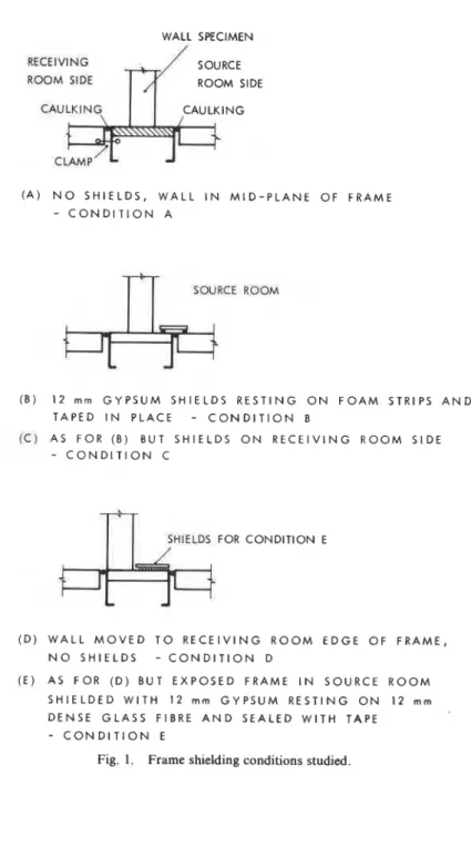
WALL SPECIMEN RECEIVING SOURCE ROOM SIDE ROOM SIDE
( A ) N O S H I E L D S , W A L L I N M I D - P L A N E O F F R A M E - C O N D I T I O N A
rT
SWRCE ROOM (B) 12 rnrn G Y P S U M S H I E L D S R E S T I N G O N F O A M STRIPS A N D T A P E D I N P L A C E-
C O N D I T I O N B ( c ) AS F O R ( 8 ) BUT S H I E L D S O N R E C E I V I N G R O O M S I D E - C O N D I T I O N CI
I
SWlELDI FOR CONDITION E( D ) W A L L M O V E D T O R E C E I V I N G R O O M E D G E O F F R A M E , N O S H I E L D S - C O N D I T I O N D (E) A S F O R ( D ) B U T E X P O S E D F R A M E I N S O U R C E R O O M S H I E L D E D W I T H 1 2 mrn G Y P S U M R E S T I N G O N 1 2 mm D E N S E G L A S S FIBRE A N D S E A L E D W I T H TAPE
-
C O N D I T I O N E310 A. C. C. WARNOCK
records. The wall (No. 1) used during these investigations comprised 65 mm steel
studs spaced 610 mm between centres, with 50 mm of low density glass fibre in the
stud space. A layer of 13 mm gypsum wallboard was screw applied to each side of the
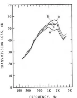
studs. The joints between sections of the wall were sealed using caulking compound and fabric tape to simplify dismantling and reconstruction. Four conditions of this wall in the frame, designated A to D, were investigated and the details are shown in Fig. 1 . The measured transmission losses for each case are shown in Fig. 2. These data were obtained without benefit of a computer analysis system, but nine microphones were still in use in each room so that the repeatability and precision of the measurements are good enough to allow one to say that the observed differences are real.
F R E Q U E N C Y , H z
Fig. 2. Measured transmission for shielding conditions A, B, C, D, Wall No. 1 .
When the specimen is at the receiving room edge of the frame (condition D), it might be assumed that flanking transmission through the frame has been eliminated since the frame is not exposed to the receiving room. Recent measurements show
that this is not the case. Wall No. 2 comprised 92 mm steel studs spaced 610 mm
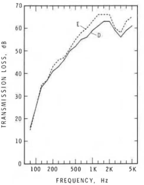
between centres with 73 mm of low density glass fibre in the cavity. The receiving room side consisted of two layers of 13 mm gypsum board and the source room side consisted of three layers of 13 mm gypsum board. The wall was placed a t the
receiving room edge of the frame, as in condition D, but in this case the exposed
SOUND TRANSMISSION LOSS MEASUREMENT 31 1 25 mm layer of high density, semi-rigid glass fibre was placed behind the shields. This is condition E in Fig. 1.
The results of the shielding procedure for this arrangement are shown in Fig. 3. It is again clear that there is a significant increase in the measured transmission loss when the frame is shielded from the sound field.
F R E Q U E N C Y , H z
Fig. 3. Measured transmission for shielding conditions D and E, Wall No. 2.
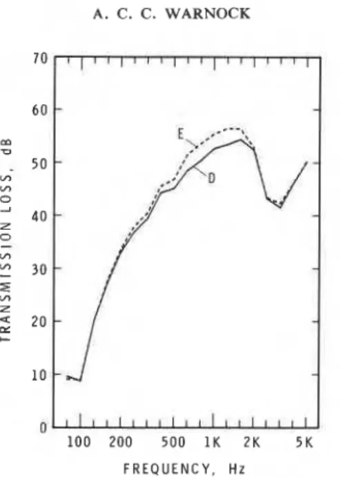
Figure 4 shows the effect of the shields for a wall similar to wall No. 1, the bnly nominal difference being a slightly thicker layer of low density glass fibre (73 mm). As this latter wall (No. 3) was constructed several years after wall No. 1, there are undoubtedly construction differences that would prevent any meaningful com- parison between the two unshielded measurements in Figs 2 and 4. The increased transmission losses due to use of the shields, however, are again quite evident.
Where flanking transmission is along an independent path having a high equivalent sound transmission loss, it becomes significant only when it is comparable with the specimen transmission loss. For this type of enhanced
transmission this is not true, as the measurements with and without shields in Fig. 5
clearly show. Here the wall specimen was a single leaf comprising two layers of 13 mm gypsum board screw attached to 41 mm steel studs spaced 610mm between centres for support (Wall No. 4). Even with this comparatively poor wall the effect of the frame is evident and the differences are significant.
A. C. C. WARNOCK
0
100 200 500 1K 2K 5K
F R E Q U E N C Y , Hz
Fig. 4. Measured transmission for shielding conditions D and E, Wall No. 3.
F R E Q U E N C Y . H z
SOUND TRANSMISSION LOSS MEASUREMENT 313
way. In each case there was a marked increase in the measured transmission loss values. An initial attempt was made to calculate the equivalent flanking trans-
mission for this phenomenon, but examinati~n~of all the data showed that the effect
of the frame varied as the wall changed. Thus any equivalent flanking transmission
calculated from the data in Fig. 5 would be meaningless if applied as a correction to
the unshielded data in Fig. 3 . The simplest way to deal with this problem is to use adequate shielding procedures in all tests.
The influence of the frame in transmission loss measurements was touched on
briefly in the model study reported by M i c h e l ~ e n . ~ Jones4 also discussed some of the
effects of specimen frames on measurements but his comments were mainly concerned with the effect of a line connection around the periphery of a double
panel, whereas the measurements in Fig. 5 show that the frame can be an important
factor in measurements of single-leaf panels.
Although the frame represents, at best, only a stub of a flanking structure, it is nevertheless clear that the coupling between it and the specimen under test acts to increase the measured transmission. The exact nature of the mechanisms involved has not been established.
It is rather obvious from this that the supporting frame should not be attached to any of the test rooms, since the connection and resulting vibrational transfer of energy constitute a form of flanking transmission in contradiction in the stated intent of both I S 0 140 and ASTM E90. A supplementary experiment with a wall intermediate in performance between walls Nos 1 and 2 showed that clamping the frame to the receiving room reduced the transmission loss by about 1 dB at 250 Hz. No other effect was discernible.
CONCLUSION
The most important conclusion from this work is that in laboratories where frames are used to support specimens it should be established by measurements such as these that the effects of the particular frame in use are not important or can be eliminated.
ACKNOWLEDGEMENT
This paper is a contribution from the Division of Building Research, National Research Council of Canada, and is published with the permission of the Director of the Division.
A . C. C. WARNOCK REFERENCES
1 . ANON., International Standard I S 0 14011 -1 978.
2. ANON., ASTM E90-75, Standard Method for Laboratory Measurement of Airborne Sound Transmission Loss of Building Partitions.
3. N . MICHELSEN. The effects oflaboratory design on the measured sound reduction index, Report NO. 18, Lydteknish Laboratorium, Akademiet for de tekniske Videnskaber, 1979.
4. R. E. JONES, lntercomparisons of laboratory determinations ofairborne sound transmission loss,
I I
A
SELECTION OF BOOKS PUBLISHED
BY
I
APPLIED SCIENCE PUBLISHERS
SOUND, MAN AND BUILDING
by L. H. Schaudinischy
54
x
84". xv+
413 pages. 231 illus.ARCHITECTURAL ACOUSTICS
by Anita Lawrence
54
x
SF. xiii+
235 pages. 84 illus.AUDITORIUM ACOUSTICS
edited by R. Mackenzie
6
x
9". xii+
231 pages. 162 illus.ROAD TRAFFIC NOISE
edited by A. Alexandre et al.
6
x
9". vii+
219 pages. 73 illus.ROOM ACOUSTICS-2nd Edition
by H. Kuttruff
6
x
9". xxiii+
309 pages. 110 illus.COMMUNITY NOISE RATINGS
by Theodore J. Schultz 6
x
9". v+
92 pages.BUILDING ACOUSTICS
i edited by B. F. Day, R. D. Ford and P. Lord
6
x
9". viii+
120 pages. 70 illus.INTRODUCTION TO ACOUSTICS
by R. D. Ford
6
x
9".ix
+
154 pages. 67 illus.A
SELECTION OF BOOKS PUBLISHED BY
APPLIED SCIENCE PUBLISHERS
DEVELOPMENTS IN LIGHTING-1 edited by J. A. Lynes
6
x
9". x+
220 pages. 71 illus.BUILDING SCIENCE LABORATORY MANUAL by Henry J. Cowan and John Dixon
6
x
9". ix+
150 pages. 88 illus.GEOMETRY O F STRUCTURAL FORMS by A. Gheorghiou and V. Dragomir
8
x
lo$". xii+
307 pages. 251 illus.ENVIRONMENTAL FACTORS IN THE DESIGN O F BUILDING FENESTRATION
by B. P. Lim, K. R. Rao, K. Tharmaratnam and A. M. Mattar 53
x
8)". xii+
260 pages. 142 illus.SOLAR RADIATION CONTROL IN BUILDINGS by E. L. Harkness and M. L. Mehta
54
x
84". xiii+
285 pages. 124 illus.AN HISTORICAL OUTLINE O F ARCHITECTURAL SCIENCE -Second Edition
by Henry J. Cowan
53
x
84". x+
202 pages. 69 illus.COMPUTER APPLICATIONS IN ARCHITECTURE edited by J. S. Gero
54
x
84". x+
413 pages. 219 illus. ARCHITECTURAL AERODYNAMICSby R. M. Aynsley, B. J. Vickery and W. Melbourne
This publication i s being distributed by the Division of Building R e s e a r c h of the National R e s e a r c h Council of Canada. I t should not be reproduced in whole o r in p a r t without p e r m i s s i o n of the original publisher. The Di- vision would be glad to b e of a s s i s t a n c e in obtaining s u c h p e r m i s s i o n .
Publications of the Division m a y b e obtained by m a i l - ing the a p p r o p r i a t e r e m i t t a n c e ( a Bank, E x p r e s s , or P o s t Office Money O r d e r , o r a cheque, m a d e payable to the R e c e i v e r G e n e r a l of Canada. c r e d i t NRC) t o the National R e s e a r c h Council of Canada, Ottawa. K I A OR6.
Stamps a r e not acceptable.
A lis t of a l l publications of the Division is available and m a y be obtained f r o m the Publications Section, Division of Building R e s e a r c h , National R e s e a r c h Council of Canada. Ottawa. KIA OR6.