HAL Id: hal-01022510
https://hal-enac.archives-ouvertes.fr/hal-01022510
Submitted on 29 Sep 2014
HAL is a multi-disciplinary open access
archive for the deposit and dissemination of
sci-entific research documents, whether they are
pub-lished or not. The documents may come from
teaching and research institutions in France or
abroad, or from public or private research centers.
L’archive ouverte pluridisciplinaire HAL, est
destinée au dépôt et à la diffusion de documents
scientifiques de niveau recherche, publiés ou non,
émanant des établissements d’enseignement et de
recherche français ou étrangers, des laboratoires
publics ou privés.
Implementation of Code Shift Keying signaling
technique in GALILEO E1 signal
Axel Javier Garcia Peña, Marie-Laure Boucheret, Christophe Macabiau,
Jean-Louis Damidaux, Lionel Ries, Stéphane Corazza, Anne-Christine Escher
To cite this version:
Axel Javier Garcia Peña, Marie-Laure Boucheret, Christophe Macabiau, Jean-Louis Damidaux,
Li-onel Ries, et al.. Implementation of Code Shift Keying signaling technique in GALILEO E1 signal.
NAVITEC 2010, 5th ESA Workshop on Satellite Navigation Technologies and European Workshop
on GNSS Signals, Dec 2010, Noordwijk, Netherlands. pp 1-8, �10.1109/NAVITEC.2010.5708056�.
�hal-01022510�
Implementation of Code Shift Keying signalling
technique in GALILEO E1 signal
Axel Garcia Peña
ENAC Toulouse, FranceMarie-Laure Boucheret
ENSEEIHT Toulouse, FranceChristophe Macabiau
ENAC Toulouse, FranceJean-Louis Damidaux
Thales Alenia SpaceToulouse, France
Lionel Ries
CNES Toulouse, France
Stéphane Corazza
Thales Alenia Space Toulouse, FranceAnne-Christine Escher
ENACToulouse, France
Abstract—One of limitations of the current GNSS signals is their
low data information rate. This low data information rate does not allow, for example, the transmission of additional commercial services or the transmission of redundant ephemeris data. The Code Shift Keying (CSK) is a signaling technique specifically designed to increase the transmission bit rate of a spreading spectrum signal. Therefore, one solution to increase the data information rate of the GNSS signals is to introduce the CSK technique in them.
In this paper, the implementation of the CSK technique into GNSS signals is inspected through the development and analysis of the likelihood ratio expression of the bits transmitted inside a CSK symbol, and through the identification of the best mapping between bits belonging to a word and bits transmitted inside a CSK symbol. Finally, the impact of the CSK technique on the GALILEO E1 signal is analyzed by calculating the CSK demodulation performance for a given scenario and the drawbacks of the technique on the signal acquisition and tracking processes.
Keywords-CSK, demodulation performance, BER, WER, likelihood ratio, CSK mapping, CSK tracking, CSK acquisition
I. INTRODUCTION
The current and future GNSS signals such as GPS L2C, GPS L5, GPS L1C and GALILEO E1 signals have improved the demodulation performance of the original GPS L1 C/A signal by means of new navigation message structures, the implementation of more advanced channel codes and the introduction of interleavers.
One last option still to be explored in order to improve the demodulation performance of these signals is the increase of the temporal diversity of the transmitted information by increasing the repetitions of the satellite ephemeris data in order to allow the receiver to obtain the information more quickly or to accumulate the information for a lower required demodulation C/N0 threshold.
Moreover, the mass market of the GNSS systems is still growing and new applications as well as services which were
not thought as useful or profitable in the past can now present themselves as great commercial opportunities.
The problem with these future services, as well as with the repetition of the ephemeris data, is the lack of available signal transmission bit rate of the GNSS signals.
In order to increase the GNSS signals data information rate, we introduce a signalling technique specially designed to increase the transmission bit rate of a spreading spectrum signal. This technique is known as Code Shift Keying or CSK. The CSK signalling technique consists in circularly shifting each transmitted PRN code in order to represent with each circularly shifted version of the PRN code a different CSK symbol mapping a fixed quantity of bits. Therefore, if each period of the data channel PRN code is equal to the duration of the data symbol, the bit transmission rate is increased proportionally to the number of bits mapped by a CSK symbol.
In this paper, first we present the fundamentals of the CSK signalling technique. After, we analyze the CSK technique by first presenting its general demodulation performance when using hard decision output demodulators. Second, we develop the theoretical mathematical expressions of the likelihood ratios of the bits mapped by a received CSK symbol. Third, we analyze what is the optimal mapping between the bits of the code words to be transmitted and the bits mapped by a single CSK symbol.
Moreover, the demodulation performances of the GALILEO E1 signal when implementing the CSK technique for different number of bits mapped by a single CSK symbol is presented for hard decision output demodulators and for soft output demodulators when the information is protected by an LDPC channel code.
Finally, the drawbacks introduced by the CSK implementation to a modern GNSS signal on the acquisition and tracking processes are presented.
Note that the CSK technique is implemented in the LEX signal of the Japanese global positioning service, QZSS, as indicated in the public released interface specification [1].
II. CSKFUNDAMENTALS
The CSK fundamentals consist of the CSK definition, of the mathematical characterization, of the CSK modulator and demodulator blocks schemes and of the biorthogonal CSK.
A. CSK Definition
The Code Shift Keying is a direct-sequence spread-spectrum (DS-SS) signaling method which overcomes the spreading gain versus data rate limitations [2].
The CSK is a form of M-ary orthogonal signaling over a communication channel [3] since M orthogonal signaling waveforms are used in order to transmit k = log2(M) bits. The
special characteristic of the CSK modulation with respect to the typical M-ary orthogonal signaling is that each waveform is obtained from a different circular phase shift of a single maximal length PRN code; where each circular phase shift is made by an integer number of chips [2]. In other words, the CSK modulation generally adopts a maximal-length sequence (m-sequence) with its period equal to M as its fundamental sequence. And each set of input data bits is represented by a signaling code, where each signaling code is obtained by cyclically shifting the adopted fundamental sequence. Each cyclically shifted sequence is assumed to be a full period version of the fundamental sequence [4].
B. CSK Mathematical characterization
Each single CSK symbol modulates k bits using the CSK technique. The number of circularly shifted versions of the fundamental code is equal to M, where M = 2k. The CSK fundamental code is called cd(t) and has a period length equal
to T which spans over L chips. L is not necessarily equal to M and the chip interval is equal to Tc. From this fundamental code
cd(t), the modulator generates the M circularly shifted versions
of the code which are called cd(t) to cd-M+1(t). Each symbol is
represented by different k bits, and the set of symbols generates a M-ary alphabet. Moreover, each circularly shifted version of the fundamental code is also called waveform. A mathematical expression of a generic circularly shifted version of the code is shown below:
[
]
( )(
)
0
..
1
)
(
=
−
⋅
mod ⋅=
−
−t
c
t
m
T
x
M
c
d x d x c LTc (1)[
x L]
d x dk
c
k
m
c
−[
]
=
−
mod (2)• mx: Integer number representing the code shift of the
xth waveform
Once the waveform has been selected, it is modulated at a carrier frequency Ȧ0, and after its transmission through an
AWGN channel the received signal at the receiver antenna output can be modeled as:
)
(
)
(
)
(
t
s
t
n
t
v
=
+
(3))
cos(
)
(
)
(
t
A
c
t
0t
s
=
⋅
d−x⋅
ω
(4)• v(t): Received signal at the receiver antenna output • s(t): Transmitted signal at the transmitter antenna input
• n(t): AWGN with power equal to ı2
.
C. Modulator Block Scheme
The modulator scheme of a CSK transmitted signal can be modeled as shown below:
Figure 1. CSK Modulator Block Scheme
D. Demodulator Block Scheme
One possible demodulator block scheme is presented. This demodulator block uses Fourier and Inverse Fourier transforms [5] whereas another possible demodulator scheme uses matched filters, one filter for each circularly shifted version of the PRN code. Nevertheless, the mathematical expression of the output of each demodulator is the same.
Figure 2. CSK Demodulator Block Scheme
Where w(t) is the received signal at the RF/IF block output. Each component of the vector represents the correlation between the received signal and a circularly shifted version of the fundamental PRN code.
Assuming that w(t) can be mathematically modeled as:
)
(
)
(
)
(
t
s
t
n
t
w
=
+
(5)• n(t): Additive narrow-band Gaussian noise with a power Pn = B·N0
• B: RF/IF filter bandwidth
The mathematical expression of the output of the CSK demodulator block scheme is:
1
..
0
1
−
=
¯
®
≠
=
+
±
=
i
M
i
x
n
i
x
n
y
i i i (6)• ni: Independent narrow-band Gaussian noises with
power equal to ı2 = Rs·N0
• Rs: CSK symbol transmission rate
E. Biorthogonal and Orthgonal CSK
In addition to use M circularly cyclic shifts of the fundamental PRN code to encode k = log2(M) bits, we can
map one extra bit with the same number of M circularly cyclic shifts as done in the M-ary biorthogonal signaling technique. Therefore, in this paper, we call orthogonal CSK the CSK method inspired from the M-ary orthogonal signaling technique and biorthogonal CSK to the CSK method inspired from the M-ary biorthogonal signaling.
Note that a M-ary biorthogonal signaling method is equivalent to a M/2-ary orthogonal signaling method where the two polarities –or signs– of the M/2 different symbols are used. III. CSK IMPLEMENTATION INTO A GENERIC GNSS SIGNAL
In this section, the characteristics of a CSK technique implemented on a generic GNSS signal are analyzed. These characteristics are the CSK demodulation performance when using a hard output decisions, the likelihood ratio expressions of the CSK bits and the optimal CSK mapping between the bits belonging to a word and the bits transmitted inside a CSK symbol.
A. CSK theoretical hard decision demodulation perfromance
The CSK is a type of M-ary orthogonal signaling (MOS) as verified by [5]. Therefore, the hard demodulation performance in terms of BER as a function of the Eb/N0 has already been
calculated and largely commented in the literature [6]. The same can be said for a biorthogonal CSK with respect to a M-ary biorthogonal signaling.
The BER of an orthogonal CSK as a function of the message Es/N0 is equal to [6]:
³
+∞³
∞ − − ∞ − − » » ¼ º « « ¬ ª ¸¸¹ · ¨¨© § − − » » ¼ º « « ¬ ª ¸ ¹ · ¨ © § − = dy N E y dx e P S M y x M 2 0 1 2 / 2 2 1 exp 2 1 1 2 1 2 π π (7) M k k P BER 1 2 2 1 − = − (8)( )
k N E N Eb S 10 0 0 log 10⋅ − = (9)• Es/N0: signal symbol energy per symbol to noise power
density ratio
• PM: Probability of orthogonal CSK symbol error
The BER of a biorthogonal CSK as a function of the Es/N0
is equal to [6]: ( )
³
+∞³
− − − + + − − ¸ ¹ · ¨ © § − = 0 2 0 0 2 / 2 2 / 1 2 / / 2 / 2 2 / 2 1 2 1 1 N E v M N E v N E v x M S S S dv e dx e P π π (10) M k k P BER 1 2 2 1 − ≈ − (11)• Es/N0: signal symbol energy per symbol to noise power
density ratio
• PM: Probability of biorthogonal CSK symbol
B. CSK likelihood ratios mathematical expressions
The bits transmitted inside the CSK symbols will very probably be encoded with a channel code in order to decrease the Eb/N0 required to obtain a desired BER. The most powerful
channel codes use soft inputs; therefore in order to implement these channel codes, the likelihood ratio (LR) expressions of the bits transmitted inside a CSK symbol have to be developed.
1) M-ary orthogonal signaling likelihood ratio expression
The likelihood ratio (LR) of the transmitted mth bit (bm) of a
orthogonal CSK is defined as shown below:
) 0 ( ) 1 ( ) ( Y b P Y b P b LR m m m = = = (12)
This expression when the transmitted bits are equiprobable is equal to: ) 0 ( ) 1 ( ) ( = = = m m m b Y P b Y P b LR (13)
The numerator and denominator probabilities cannot be directly obtained since the probabilities obtained from the observation of the Y vector (CSK demodulator) determine the probability of receiving a symbol rather than the probability of receiving only one individual bit.
The observed probability expression for a given group of transmitted bits or symbol is shown below.
(
)
(
k)
k observedP
Y
b
b
b
P
Y
B
P
=
−1,
!
,
1,
0=
(14),
,
,
,
1 0 1b
b
b
B
k=
k−!
(15) • Bk: Set of k bits determining the transmitted symbol • bx: Value of the xth bit of the set Bk
From equation (14), the probability of receiving Y when bm
is equal to 0 or to 1 can be calculated as presented next:
(
)
(
)
(
1 1 1 1 0 0)
0 0 1 1 1 1 , , , 1 , , , , , , 1 , , 1 1 x b x b b x b P x b x b b x b Y P b Y P m k k x x m k k m K = = = = ⋅ = = = = = = − − − −¦ ¦
! ! ! ! " (16)Note that in equation (16), the only summation which is not applied is the summation having as subindex xm.
The summation having as subindex xp has to be interpreted
as shown below. ) 0 ( ) 0 ( ) 1 ( ) 1 ( ) ( ) ( = ⋅ = + = ⋅ = = = ⋅ =
¦
p p p p x p p p p b P b P b P b P x b P x b P p (17)Since the bits are equiprobable, equation (16) is simplified to:
(
)
(
)
¦¦ ¦
− − − = = = ⋅ = = 0 1 1 1 1 0 0 , , 1, , 1 1 x x x k k m m k x b b x b Y P M b Y P ! ! " (18)The individual terms of equation (18) can be determined since they are the probability of the Y vector observation when a determined group of bits, Bk, is transmitted. Using equation (14), the previous expression can be expressed as
(
=
)
=
⋅
¦
(
=)
n bm n k mP
Y
B
M
b
Y
P
,
11
1
(19) • Bkn,bm=1: Set of k bits mapped by symbol n. The bit bm
of symbol n is equal to 1.
The conditioned probability of the Y vector observation can be modeled as a product of the conditioned probabilities of the observation of each individual Y vector component since the Y vector components are independent among them: the noise of each Y vector component is independent from the noise of any other component. The conditioned probability of the Y vector observation can be expressed as:
(
)
(
) (
)
(
k)
M k k kB
y
P
B
y
P
B
y
P
B
Y
P
=
0⋅
1⋅
!
⋅
−1 (20)From equation (6), the conditioned probability of each individual component observation can be modeled as a Gaussian variable with variance equal to ı2
, and with a mean that depends on the transmitted groups of bits, Bkn: the mean of
the yi component observation is equal to 1 if the transmitted
group of bits, Bkn, is mapped by the M-ary orthogonal symbol
i; in other words, if i is equal to n. Otherwise the mean is 0. The probabilities of the observation of the Y vector components when the group of bits, Bkn, is transmitted are:
(
)
(
)
° ° ¯ ° ° ® = ¸¸¹ · ¨¨© § − ⋅ − ⋅ ≠ ¸¸¹ · ¨¨© §− ⋅ ⋅ = n i y n i y B y P i i n k i 2 2 2 2 1 2 1 exp 2 1 2 1 exp 2 1 σ πσ σ πσ (21)Therefore, expression (20) is equivalent to:
(
)
(
)
¸ ¹ · ¨ © §− ⋅ ⋅ − ¸ ¹ · ¨ © §− ⋅ ⋅ =¦
− = 1 2 2 1 exp 2 1 exp 2 1 2 1 0 2 2 n M i i n k y y B Y P σ σ πσ (22) Finally, equation (19) can be written as shown below:(
)
¦
= ¸ ¹ · ¨ © § ⋅ = = m m x b i i m m y Y K x b Y P ( ) exp 2σ
(23) » ¼ º « ¬ ª ¸ ¹ · ¨ © § − ⋅ =¦
− = 1 0 2 2 1 2 1 exp 2 2 1 ) ( M i i y M Y Kσ
πσ
(24)The summation of the second term of equation (23) means the summation of all the yi components which represent a
symbol, or group of bits, Bk, having bm = xm.
Finally, since K(Y) has the same value for bm=1 and bm=0,
the final expression of the likelihood ratio of the bits mapped by a M-ary orthogonal symbol is:
¦
¦
= =¸
¹
·
¨
©
§
¸
¹
·
¨
©
§
=
0 2 1 2exp
exp
)
(
m m b i i b i i my
y
b
LR
σ
σ
(25)Finally, an algorithm to speed the bits likelihood ratio calculation is presented:
1. Calculating and storing all the exponential values: Tm =
exp(ym/ı2)
2. Setting the value M = 2k 3. For i = 0 to k-1
a. Calculating the bi likelihood ratio
i. P1 = T1 + T3 + … + TM-1
ii. P0 = T0 + T2 + … + TM-2
iii. LR(bi) = P1/P0
b. Calculating the new Tm values
i. For m = 0 to (M/2 – 1) Æ Tm = T2m + T2m+1
c.
Setting the new M value: M = M/2This algorithm is illustrated and justified in the figure displayed below. In this example, 4 bits are modulated in a 16-ary orthogonal symbol.
Figure 3. 16-ary orthogonal signalling example - Bits likelihood ratio calculation for 4 bits mapping an orthogonal signal
2) M-ary biorthogonal signaling likelihood ratio expression
In the case of a M-ary biorthogonal signaling, the search of the bits likelihood ration expression is different from the bit indicating the polarity of the transmitted waveform to the bits selecting the transmitted waveform.
The mathematical notation for a biorthogonal CSK mapping is:
{
,
b
2,
b
2,
,
b
0}
R
k=
β
k− k−!
(26){
1}
,
−=
k kB
R
β
(27) • Rk: Set of k input bits for a biorthogonal CSK symbol • ȕ: Value of the bit setting the waveform polarity • Bk-1
: Set of k-1 input bits for a orthogonal CSK symbol • bx: Value of the xth bit of the set Bk-1
The likelihood ratio expression of the bit setting the waveform polarity is calculated using equation (13):
) 0 ( ) 1 ( ) ( = = = β β β Y P Y P LR (28)
In this case, the observed probability at the demodulator output is:
(
)
(
k)
k observedP
Y
b
b
b
P
Y
R
P
=
β
,
−1,
!
,
1,
0=
(29)Therefore, denoting each different group of transmitted bits mapped by the M/2-ary orthogonal symbol as Bkn and denoting
each different group of transmitted bits by the M-ary biorthogonal symbol as Rkn, the conditioned probability of the
observation of the Y vector component yi can be modeled as:
(
)
(
)
° ° ¯ ° ° ® = ¸¸¹ · ¨¨© § + ⋅ − ⋅ − ⋅ ≠ ¸¸¹ · ¨¨© § ⋅ − ⋅ = n i y n i y R y P i i n k i 2 2 2 2 1 2 2 1 exp 2 1 2 1 exp 2 1 σ β πσ σ πσ (30)Consequently, expression P(Y|Rkn) is equal to:
(
)
¸¸¹ · ¨¨© § ¸¸¹ · ¨¨© § ¸ − ¹ · ¨ © § − ⋅ ⋅ − ¸ ¹ · ¨ © §− ⋅ ⋅ =¦
− = 1 2 1 2 2 1 exp 2 1 exp 2 1 2 1 2 / 0 2 2 n M i i n k y y R Y P β σ σ πσ (31) The likelihood ratio expression of the bit setting the waveform polarity can be found from equations (19), (28) and (31):¦
¦
− = − =¸
¹
·
¨
©
§
¸
¹
·
¨
©
§
−
=
1 2 / 0 2 1 2 / 0 2exp
exp
)
(
M i i M i iy
y
LR
σ
σ
β
(32)The likelihood ratio expressions of the bits selecting the transmitted waveform are calculated taking into account the probability of having received the ȕ bit equal to 0 or equal to 1.
(
) (
)
(
) (
)
(
Yb) (
P Y)
P(
Yb) (
P Y)
P Y P b Y P Y P b Y P b LR m m m m m 1 1 , 0 0 0 , 0 1 1 , 1 0 0 , 1 ) ( = ⋅ = = + = ⋅ = = = ⋅ = = + = ⋅ = = = β β β β β β β β (33)The terms P(Y|bm, ȕ) can be calculated as showed in
equation (19) using equation (14) for the M-ary orthogonal signaling case. The only difference is found when ȕ=1 since the value of ym has its sign inversed in this case.
(
)
(
)
⋅
¦
(
= =)
=
=
=
n xm bm n k m mR
Y
P
M
x
b
Y
P
0,
,
2
1
,
0 β ββ
β
(34)Thus, P(Y|bm, ȕ) can be expressed from (31) and (34) as:
(
)
(
)
¦
(
)
= ¸ ¹ · ¨ © § ⋅ − ⋅ ⋅ = = m m x b i i m m y Y K x b Y P , , exp 2 0.5 2 σ β β β (35) » ¼ º « ¬ ª ¸ ¹ · ¨ © § − ⋅ =¦
− = 1 2 / 0 2 2 1 2 1 exp 2 1 ) , ( M i i y M Y K σ πσ β (36)As before, K(Y,ȕ) has the same value for bm = 0 and for bm
= 1. Therefore, the likelihood ratio expression is:
¸ ¸ ¸ ¹ · ¨ ¨ ¨ © § ¸ ¹ · ¨ © §− ⋅ ¸¸¹ · ¨¨© § ¸ ¹ · ¨ © §− + ¸ ¸ ¸ ¹ · ¨ ¨ ¨ © § ¸ ¹ · ¨ © § ⋅ ¸¸¹ · ¨¨© § ¸ ¹ · ¨ © § ¸ ¸ ¸ ¹ · ¨ ¨ ¨ © § ¸ ¹ · ¨ © §− ⋅ ¸¸¹ · ¨¨© § ¸ ¹ · ¨ © §− + ¸ ¸ ¸ ¹ · ¨ ¨ ¨ © § ¸ ¹ · ¨ © § ⋅ ¸¸¹ · ¨¨© § ¸ ¹ · ¨ © § =
¦
¦
¦
¦
¦
¦
¦
¦
= − = = − = = − = = − = 0 2 1 2 / 0 2 0 2 1 2 / 0 2 1 2 1 2 / 0 2 1 2 1 2 / 0 2 exp exp exp exp exp exp exp exp ) ( m m m m b i i M i i b i i M i i b i i M i i b i i M i i m y y y y y y y y b LR σ σ σ σ σ σ σ σ (37)3) Likelihood ratios mathematical expression verification
We have simulated the transmission of a CSK signal through an AWGN channel and we have calculated the BER using hard decisions outputs and using the likelihood ratio expressions developed previously. The simulations show that all the inspected methods provide the same BER as a function of the signal Eb/N0 at the correlator output. This means that the
previous CSK bits likelihood ratio expressions are verified as the equivalent soft output method of the hard decision method defined by the literature [6].
The demodulation performance of the transmission of a CSK signal through an AWGN channel when 8 bits are mapped by a CSK symbol is presented below. Figure 4 shows the BER as function of the signal Eb/N0 at the correlator output.
Figure 4. BER vs Eb/N0 for a transmission employing CSK symbols which
map 8 bits
The same results have been obtained for 6 and 10 bits mapped by a CSK symbol [7].
C. Source Words Mapping of a CSK modulation
The implementation of a channel code on the bits transmitted by a CSK modulation introduces a new interesting element of study: the CSK source word mapping.
The source word mapping is defined as the distribution between the bits mapped by each CSK symbol and the bits belonging to the same word: which bits mapped into a CSK symbol belong to a given word A, which bits belong to a given word B, etc. Therefore, one question to be asked is which source word mapping provides the lowest BER.
In fact, the variance of the number of errors of a word transmitted by a CSK signal depends significantly on the used CSK source word mapping. And, as justified next, it can be
much more interesting to have either a low or a large variance depending on the transmission channel.
On one hand, if the variance is low and the error correction capacity of the implemented channel code is larger than the average number of errors, the channel code could correct almost all the words. On the other hand, if the variance is large and the error correction capacity of the implemented channel code is much smaller than the average number of errors, the channel code could correct some words whereas with a low variance no word should be corrected.
The calculation of the variance of the number of errors of a word transmitted inside CSK symbols is made in three steps. The first step is to calculate the probability of having n erroneous bits among x bits belonging to the same packet when the transmitted CSK symbol maps K bits and has a probability of error equal to PM. The mathematical expression of the
probability is given next [7]:
(
)
(
)
n x m x K n x n P K n p x K n m K M x ¸¸¹ ≤ · ¨¨© § − −¸¸¹ · ¨¨© § + ⋅ − =¦
− = () 1 2 ) ( 1 δ δ (38)• į(n): Dirac delta function
The second step consists in calculating the probability of a word of L bits having 0 erroneous bits, the probability of having 1 erroneous bit, etc, until the probability of having L erroneous bits. This second step is made using Matlab since it is the raw combination of the probabilities expressed in (38).
The third and final state is the calculation of the average and the variance of the number of errors of a word transmitted into CSK symbols using the probabilities determined in step 2.
Finally, the CSK source word mappings determining the lowest and largest variance of the number of errors of a word transmitted inside CSK symbols are determined by inspecting the results of step 3 for a CSK symbol mapping 8 bits. Figure 5 show the desired variance as a function of the signal Es/N0 for a
word of 1200 bits.
Figure 5. Variance of the number of bit errors of a word of 1200 bits transmitted by 256-CSK symbols with different CSK source packet mappings
From figure 5, it can be observed that the CSK source word mapping which obtains the lowest variance of the number of errors of a word transmitted inside a CSK symbol is the
mapping where all the bits transmitted inside a CSK symbol belong to different words. Moreover, it can be observed that the largest variance belongs to the mapping where all the bits transmitted inside a CSK symbol belong to the same word.
The same results have been observed for 4, 6, 10 and 12 bits mapped by a CSK symbol [7].
IV. CSKIMPLEMENTATION IN THE GALILEOE1SIGNAL The CSK implementation on the GALILEO E1 signal consists in applying the CSK technique, the circular shift of the PRN code, on the data channel and in using the pilot PRN code as synchronizer in order to identify which circular shift has been transmitted.
In this section, the hard decision output demodulation performance of the GALILEO E1 signal is given, the demodulation performance of the GALILEO E1 signal with an implemented LDPC code is presented, and the CSK influence on the tracking and the acquisition process is analyzed.
A. CSK hard output demodulation of the GALILEO E1
The hard output performance of the GALILEO E1 signal without implemented channel code is calculated from the theoretical expressions (8) and (11).
This calculation assumes that the signal C/N0 or Es/N0 is
fixed for any number of bits transmitted inside a CSK symbol which means that the Eb/N0 varies for the different number of
bits.
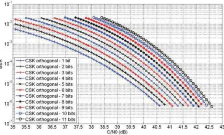
The number of chips of the GALILEO E1 PRN data code is 4092 which means that a maximum of 11 bits are transmitted with an orthogonal CSK and a maximum of 12 bits are transmitted with a biorthogonal CSK. The bit transmission rate (RD) is equal to 250 bit/s.
Figures 6 and 7 show the BER of the GALILEO E1 signal for a hard decision demodulation as a function of the signal C/N0 at the correlator output. From these figures, it is observed
that due to the constant value of Es, a larger number of bits
mapped by a single CSK symbol leads to a worse demodulation performance in terms of BER of the CSK modulation in the GALILEO E1 signal.
Figure 6. BER vs C/N0 of the part of the GALILEO E1 signal implementing
the CSK signalling technique for different number of bits mapped by an biorthogonal CSK symbol
Figure 7. BER vs C/N0 of the part of the GALILEO E1 signal implementing
the CSK signalling technique for different number of bits mapped by an orthogonal CSK symbol
B. CSK soft demodulation performance for GALILEO E1
The demodulation performance of the GALILEO E1 signal which implements the CSK and which has a channel code applied on the CSK information bits is presented. This section uses the likelihood expressions developed in section III.B.
The bit transmission rate of the signal is 250 bits/s. The size of the information word is 600 bits which are encoded with the LDPC code of GPS L1C [8] resulting into a coded word of 1200 bits. The orthogonal and biorthogonal CSK are implemented and the CSK source word mapping providing the lowest and the largest variance are analyzed. For the latter mapping, an interleaver applied over the word is introduced in order to break the burst of errors and, thus, to improve the demodulation performance.
The next figures show the BER of the GALILEO E1 signal implementing a CSK technique which maps 8 bits for each CSK symbol as a function of the signal C/N0 at the correlator
output. An ideal estimation of the signal carrier phase and the code delay is assumed.
Figure 8. BER vs C/N0 of different CSK configurations where each CSK
symbol maps 8 bits when the signal is transmitted through an AWGN channel
From figure 8, it can be seen that the CSK source word mapping providing the lowest variance outperforms the mapping providing the largest variance. This demodulation
performance difference grows along the increase of the number of bits mapped by a CSK symbol as seen in [7].
Moreover, it can also been observed that the orthogonal CSK slightly outperforms the biorthogonal CSK, but this difference decreases along the increase of the number of bits as seen in [7].
From figures 6, 7 and 8, it can be observed that for a BER equal to 10-6, the provided gain between a CSK configuration mapping 8 bits without a channel code and the same configuration but with the GPS L1C LDPC code is about 6.45 dB for the orthogonal CSK and is about 6.5 dB for the biorthogonal CSK. This gain decreases along the increase of the number of bits mapped by a CSK symbol as seen in [7] These gains can be compared to the gain introduced by the application of the same LDPC code on a BPSK signal without the CSK technique; this gain is about 8.1 dB [7].
Finally, the BER and WER of the GALILEO E1 signal implementing an orthogonal or a biorthogonal CSK configuration with the source word mapping providing the lowest variance and for different number of bits mapped by a CSK symbol as a function of the signal C/N0 at the correlator
output are presented.
Figure 9. BER vs C/N0 of the best GALILEO E1 signal CSK configurations
Figure 10. WER vs C/N0 of the best GALILEO E1 signal CSK configurations
From figures 9 and 10, it can be seen that for any number of bits mapped by a CSK symbol, in order to obtain a BER equal
to 10-6 or a WER equal to 10-3 we need a C/N0 larger than 34
dB-Hz.
C. Drawbacks of the CSK on the GALILEO E1 signal
The main disadvantage of the CSK technique implementation on the GALILEO E1 signal is the constant shift of the data PRN code which does not allow the use of the data channel in the acquisition and in the tracking process.
1) Tracking process:
The new GNSS signals are formed by two channels, the data channel and the pilot channel, in order to avoid the limitation of the maximal coherent integration time imposed by the data symbol duration. This means that the tracking of new GNSS signals was thought to be made only on the pilot channel.
Moreover, wipe-off techniques are also allowed by the data PRN code implementing the CSK technique, since the knowledge of the transmitted bits determines the next circular shift of the PRN code. The only difference is that a larger quantity of bits must be known to be able to apply the wipe-off techniques.
To sum up, the tracking process is not affected by the implementation of the CSK signaling technique.
2) Acquisition process:
The acquisition process of the GALILEO E1 signal is affected by the implementation of the CSK technique since both channels, pilot and data, are used to acquire the signal.
In order to quantify the impact of the CSK technique on the acquisition process, we have run some simulations which calculate the average acquisition time of the GALILEO E1 signal when we use both channels to acquire the signal without implementing the CSK, when we use both channels to acquire the signal implementing the CSK and when we only use the pilot channel.
The simulations use a coherent integration time of 4ms, a non-coherent integration time of 100ms, 2000 correlators and only 190 symbols out of the 250 symbols transmitted each second by the GALILEO E1 signal implement the CSK.
From figure 11, it can be observed that when the CSK is implemented, the signal has to be acquired only using the pilot channel. Moreover it can be seen that for C/N0 larger than 29
dB-Hz, the GALILEO E1 signal is acquired faster using only the pilot channel than using both channels even when the CSK technique is not implemented. Finally, it can be seen that for an average acquisition time of 1000s, we require an extra 1 dB of C/N0 when we only use the pilot channel than when we use
both channels and the CSK is not implemented. V. CONCLUSIONS
In this paper, the Code Shift Keying signaling technique has been presented as a possible option for the future GNSS signals in order to increase their data transmission rate.
Figure 11. Average acquisition time for GALILEO E1 OS signal as a function of the data + pilot C/N0
This increase of the data information rate could be use in order to transmit additional commercial services or in order to transmit redundant ephemeris data which will reduce the C/N0
needed to obtain a desired BER or WER.
Different demodulation performance of the GALILEO E1 signal has been calculated for different CSK configurations, and the CSK impact on the tracking and acquisition process has been analyzed.
The likelihood ratio expressions of the bits transmitted inside a CSK symbol has been developed. A fast algorithm has been provided for their calculation.
ACKNOWLEDGMENT
A.G.P. thanks to CNES, TAS-F and TéSA for the joint financing of the research fellowship.
REFERENCES
[1] Japan Aerospace Exploration Agency, “Interface Specification for QZSS (IS-QZSS) Draft V1.2”, March 19, 2010
[2] A.Y.-C. Wong, and V. C. M. Leung, “Code-Phase-Shift Keying: A Power and Bandwidth Efficient Spread Spectrum Signaling Technique for Wireless Local Area Network Applications”, IEEE Canadian Conference on Electrical and Computer Engineering, 1997.
[3] J.D. Endsley, and R.A. Dean, “Multi-access properties of transform domain spread spectrum systems”, In Proceedings of the 1994 Tactical Communications Conference, Vol. 1, Digital Technology for the Tactical Communicator, 1994.
[4] Y.-R. Tsai, “M-ary Spreading Code Phase Shift Keying Modulation for DSSS Multiple Access Systems”, IEEE Transactions on communications, Vol 57, No 11, November 2009.
[5] G.M. Dillard, M. Reuter, J. Zeidler and B. Zeidler, “Cyclic Code Shift Keying: A Low Probability of Intercept Communication Technique”, IEEE Transactions on Aerospace and Electronic Systems, Vol. 39, No 3, July 2003.
[6] J.G. Proakis, Digital Communications, 4th ed, McGraw-Hill, 2001, 257-263
[7] A.J. Garcia-Pena, “Optimisation of Demodulation Performance of the GPS and GALILEO Navigation Messages”, Dissertation, Institut National Polytechnique de Toulouse, 2010.
[8] ARINC Engineering Services, “Navstar GPS space Segment/User segment L1C interfaces, Draft IS-GPS-800”, Aug 04, 2006