Publisher’s version / Version de l'éditeur:
Proceedings of the 5th Conference on Optical 3-D Measurement Techniques, 2001
READ THESE TERMS AND CONDITIONS CAREFULLY BEFORE USING THIS WEBSITE. https://nrc-publications.canada.ca/eng/copyright
Vous avez des questions? Nous pouvons vous aider. Pour communiquer directement avec un auteur, consultez la
première page de la revue dans laquelle son article a été publié afin de trouver ses coordonnées. Si vous n’arrivez pas à les repérer, communiquez avec nous à [email protected].
Questions? Contact the NRC Publications Archive team at
[email protected]. If you wish to email the authors directly, please see the first page of the publication for their contact information.
NRC Publications Archive
Archives des publications du CNRC
This publication could be one of several versions: author’s original, accepted manuscript or the publisher’s version. / La version de cette publication peut être l’une des suivantes : la version prépublication de l’auteur, la version acceptée du manuscrit ou la version de l’éditeur.
Access and use of this website and the material on it are subject to the Terms and Conditions set forth at
Real-time 3D Pose Estimation Using Photogrammetry and Laser Based
Geometrical Target Tracking for Autonomous Operation in Space
Blais, F.; Beraldin, J.-A.; El-Hakim, S.F.
https://publications-cnrc.canada.ca/fra/droits
L’accès à ce site Web et l’utilisation de son contenu sont assujettis aux conditions présentées dans le site LISEZ CES CONDITIONS ATTENTIVEMENT AVANT D’UTILISER CE SITE WEB.
NRC Publications Record / Notice d'Archives des publications de CNRC:
https://nrc-publications.canada.ca/eng/view/object/?id=e95c885b-80e9-4a47-9384-acabb9f26faf https://publications-cnrc.canada.ca/fra/voir/objet/?id=e95c885b-80e9-4a47-9384-acabb9f26faf
National Research Council Canada Institute for Information Technology Conseil national de recherches Canada Institut de technologie de l'information
Real-time 3D Pose Estimation Using
Photogrammetry and Laser Based Geometrical
Target Tracking for Autonomous Operation
in Space *
Blais, F., Beraldin, J.A., El-Hakim, S.
October 2001
* published in the Proceedings of the 5th Conference on Optical 3-D Measurement Techniques. Vienna, Austria. October 1-3, 2001. NRC 44877.
Copyright 2001 by
National Research Council of Canada
Permission is granted to quote short excerpts and to reproduce figures and tables from this report, provided that the source of such material is fully acknowledged.
Real-time 3D Pose Estimation using Photogrammetry and
Laser Based Geometrical Target Tracking for Autonomous
Operation in Space
∗F. Blais, J.-A.Beraldin, S.F.El-Hakim,
National Research Council of Canada, Institute for Information Technology, Ottawa, Ontario, Canada, K1A 0R6
∗
NRC-44877
Abstract. In this paper, we show that a 3D laser scanner tracking system can be efficiently used in a
projective mode similar to photogrammetry-based methods. The best of both laser ranging and photogrammetry can be combined to increase the accuracy and reliability of a 6 DOF pose
estimation/tracking system. Geometrical tracking and object pose evaluation using the laser scanner projective coordinate system becomes equivalent to a video camera/photogrammetry based
approach with the added feature of measuring the focus distance of the image point and being able to track geometrical features as well as targets. Tracking and ranging from either the laser scanner XYZ coordinates or the photogrammetry projective model can be used.
Key words: tracking, vision system, object tracking, pose estimation, sun interference, laser scanner,
photogrammetry.
1 Introduction
A definite key advantage of 3D vision systems over 2D video cameras is scale and rotation
invariance of the acquired 3D data as opposed to a 2D perspective projection. However 3D sensors by themselves are basically extensions of 2D techniques. Stereoscopic, photogrammetry, or laser scanners are amongst the methods that have been developed to obtain the 3D information,
orientation, and shape of objects. Active ranging methods have another advantage over their passive counterparts because of the higher 3D points density and of not being limited to specific object features and or targets. Furthermore, for space applications such as demonstrated here, the high tolerance of 3D laser scanners to ambient light and sun interferences is another important feature. On the other hand, passive photogrammetry based techniques have proven to be very accurate, especially for medium volume measurements. Only theodolites can in practice give comparable or better accuracies. Laser scanners have been demonstrated in imaging mode by providing high-resolution images but with still limited accuracy at medium range when compared to
photogrammetry. A possible solution becomes obvious: can we combine the advantages of light immunity of a 3D laser scanner system and the accuracy of photogrammetry techniques?
During the late 80s, most of the 3D laser scanner systems developed, at NRC and elsewhere, were principally limited to laboratory use and commercial systems were mostly targeted toward specific
industrial applications such as the automobile industry [1]. In the early 90s, a mobile (to
differentiate with portable) version of the NRC auto-synchronized scanner was demonstrated for the acquisition of a scaled model of the cargo bay of the space shuttle [2] and in the mid-90s with experiments in Kennedy Space Center Florida, USA.
In the early 90s, the Institute for Information Technology (IIT) of the National Research Council of Canada demonstrated the use of laser scanner technologies for space applications. The technique developed combines laser scanning technology, ranging, imaging, and tracking to compute in real-time the pose of objects [3]. This laser scanner is designed to be insensitive to background illumination such as the earth albedo and the sun and most of its reflections. To demonstrate the concept, retro-reflective targets were used and tracking was based on the intensity of the reflected laser light. In the summer of 1999, in close collaboration with Neptec Design Group [4], the laser scanner prototype was interfaced to the Space Vision System [5]. The prototype automatically searches and tracks in 3D retro-targets attached to the object. Stability of the photo-solution was advantageously compared to results obtained using existing video cameras but with the added feature of generating robust solutions in the presence of strong background illumination. With this success Neptec Design Group, the National Research Council of Canada and the Canadian Space Agency, are currently working on a space-qualified version of the Laser Scanner prototype, to be flown on board mission STS 105 during summer 2001 (see section 7).
The laser-based range scanner approach presented here offers the advantage of being close to 100% operational throughout the changing illumination conditions in orbit. This paper will present the most up-to-date results obtained with the laser tracking system and will compare the accuracy of pose estimation of objects using either the XYZ range data or the equivalent camera pin-hole/resection model using the UV coordinate system.
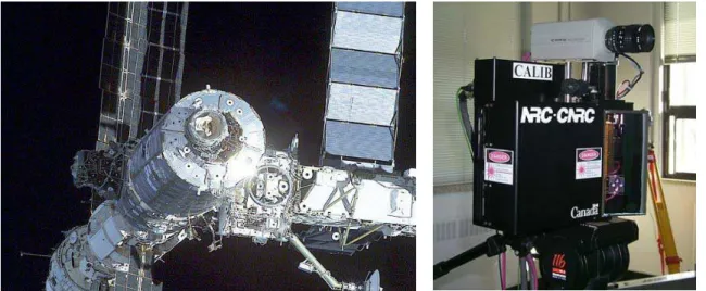
Figure 1: Effect of sun illumination on video images of
the International Space Station. The Space Vision System uses the targets on the different modules to compute their relative pose during assembly (Photo courtesy NASA).
Figure 2: Prototype of the laser scanner
system, a conventional video camera is “temporarily” mounted on the laser scanner for monitoring and comparison with conventional video methods.
2 The imaging / tracking system
The Space Vision System [6-7] tracks the small black and white dot targets visible in Figure 1. Because the exact physical locations of these features on the object are known, object position is computed from their relative positions in the video images using photogrammetry-based techniques. The laser scanner system shown in Figure 2 is used to track the targets illustrated in Figure 1. It is based on the NRC auto-synchronized principle [1] and uses two high-speed galvanometers to deflect a laser beam on the object. Ranging is obtained using triangulation. Because of the inertia and limited speed of galvanometers, a 3D laser scanner used in the conventional raster-imaging mode of operation will be very slow. Raster imaging consists of scanning the scene line-by-line, emulating the video reading mechanism of conventional CCD/CMOS cameras. Real-time tracking of targets or geometrical features on an object is implemented using Lissajous figures, to obtain good scanning speed and accuracy. Driving the two axis galvanometers with sine waves of different frequencies creates a Lissajous pattern [3]. Figure 4 illustrates the geometrical tracking principle using the 3D range information on the Lissajous pattern, to (a) identify targets on the object or any useful geometrical feature and (b) to discriminate the target from its background. Lissajous patterns are used to scan objects at refresh rates exceeding the bandwidth of the mechanical deflection system. The natural inertia of the galvanometer-mirror structure smoothes the scanning pattern and hence increases the pointing accuracy of the tracking system.
3 Integration of Laser Camera System with the Space Vision System
The Laser Camera System – SVS demonstration project had two main objectives [5]:
• To demonstrate that the accuracy performance, with the Laser Tracking System used as a sensor, is equivalent to the performance of the system using quality video cameras. • To demonstrate that the system provides greater robustness to adverse lighting conditions.
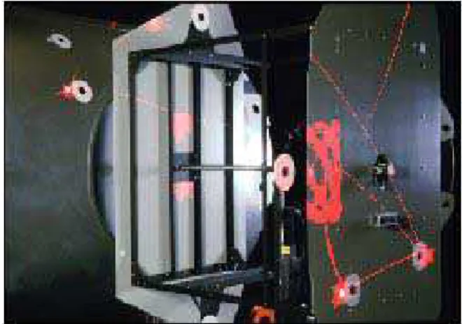
Figure 3: The Node and Z1 modules experimental
setup (1/2 scale). Two types of target are visible, Inconel B/W and retro-reflective targets. (Photo courtesy Neptec)
Figure 4. Real-time tracking of targets on the
simulated Node and Z1 modules. The system tracks each retro-target sequentially. In this example, one of the targets is in “search mode” using a larger Lissajous pattern. (Photo courtesy Neptec)
Figure 3 and 4 show the experimental setup used and the multiple targets tracking process where the laser scanner is programmed to sequentially scan different sections of the object. One of the targets is here in the search mode where the scanner uses a larger Lissajous pattern to locate it. When found, the scanner automatically switches from the search mode to the track mode using a smaller Lissajous pattern to increase target centroid accuracy. Using this method, errors introduced by the measurement process are always optimal because the scanner automatically centres and optimizes the size of the tracking patterns based on the measured target to object distance, for each target individually. The laser scanner sequentially scans different sections or targets on one or multiple objects.
The demonstration setup utilized the 3A-Z1 install task simulation in the Neptec Vision System Certification Lab (VSCL) [4]. This simulation consisted of half-scale models of the Unity and Z1 truss models with Inconel targets applied in flight locations and closely located retro-reflective targets. The results indicated that, under the correctly chosen conditions, the agreement between the camera and LCS solution was within 6 mm (0.25") and 0.25 degrees (worst case). Shining a very directional 1000-Watt light source directly at the LCS and camera. This situation was intended to simulate the condition of the sun shining directly into the camera. Testing showed that when using the video camera, the SVS based on video cameras would not continue to generate a solution. When the same test was performed with the LCS there was no loss of solution.
4 Scanner
Resection
Model
Using triangulation, the laser scanner system can measure range information (x,y,z) for each voxel (3D volumetric element) in its field of view [1]. Here, we will use the simplified model illustrated in Figure 5 to model range measurements using triangulation and to associate geometrical tracking and object pose estimation. We will use the error model as the basis to demonstrate the purpose of using the scanner coordinate system UVW for geometrical tracking and pose estimation.
Assuming a simplified aberration-free model, a vergence reduced to 0 (both laser and optical axis point to infinity) and setting R=z/cos(θ), range R can be calculated as:
) sin( ) cos(θ d θ p d f R = ⋅ + (1)
where f is the focal length of the imaging lens, d is the triangulation base, θ is the deflection angle parallel to the x-axis, and p is the position of the imaged laser spot of the position sensor. The x-y-z coordinates of a point are
(
)
+ − − ⋅ = ) cos( ) cos( )) cos( 1 ( ) sin( ) cos( ) sin( φ θ ψ φ φ ψ θ θ R z y x (2)where θ and φ are the deflection angles, and ψ=Dg/R where Dg is the separation between the
two scanning mirrors (or axis).
Figure 5. Simplified geometrical model of the
laser scanner showing the effect of astigmatism between the x and y scanning axe.
Rotation X-Axis Rotation Y-Axis X Z Y CCD Lens Dg (0,0,0) φ θ R
Since we are here mostly interested with measurement uncertainty, the error analysis using the model given by equations 2 is more than sufficient. Error propagation calculations (in triangulation mode) can be approximated, from equation 1, by
p d f R R ∆ ⋅ ≈ ∆ 2 (3)
From equation 2, the system astigmatism created by Dg, and the overall system distortions are not
negligible and will introduce bias in the measurements but since R is known from p so is ψ. For random noise analysis equations 2 and 3 are sufficient and range errors for each x-y-z coordinates;
for medium to long-range measurements (Dg<<R), are mostly contributed by ∆R i.e. proportional
to R2.
5 Geometrical
Tracking
To simplify the discussion, we are here assuming that most geometrical objects can be modeled using planar surfaces (or meshes) or simple geometries. Because the laser scanner provides range information, the equation of a surface can be defined using 0=ax+by+cz+d. Target discrimination
is obtained by removing outliers that do not belong to the plane of the target. Because most objects can be defined using planes, meshes, or simple geometries, best fit of surfaces (or simple
geometries) is a robust method for target detection and tracking as seen in Figures 6 to 8. Although the extension of the method to other geometries such as spheres will not be presented here, it is obviously possible as seen in Figure 7.
Real-time geometrical target processing and tracking in the laser scanner inverse spherical coordinate system is used. This corresponds to the angles of measurements and the inverse of the range u=x/z, v=y/z, and w=1/z [8]. Using the homogenous UVW coordinates system; the high correlation normally obtained using the three axes x-y-z in the Cartesian coordinate system relative
to the object distance R, is minimized. The UVW coordinate system also eliminates the z2
dependency of range error, linearizing the error equations, and more important, eliminating the possibility of ill-conditioned systems of equations. Of primary interest is the direct relationship between the sensor raw measurements and the equation of a plane z=ax+by+c, becoming w=αu+βv+χ. Linear minimization techniques can then be optimally used since the errors are
constant for the whole volume. Furthermore, because u and v are mostly correlated with only the
Figure 6. Tracking using
the Lissajous pattern and a planar circular target.
Figure 7. Geometrical tracking
of a sphere.
Figure 8: Tracking of natural
angles ϕ and θ, of the scanner, quadratic error minimization will never be ill conditioned, of primary importance for real-time computation.
Figure 6 demonstrates the tracking method using the plane of the target to discriminate the target from the surrounding environment and ambient light. The intensity gradient of the target is used to discriminate the target itself. Figures 7 and 8 show pure geometrical tracking. If we compare the method with a 2D video camera, the background target and the sphere will be identical (same color) and impossible to differentiate using conventional video methods. The scanning pattern is optimally scaled with the target geometry and dimensions, for each target independently, providing very accurate and stable target centroid estimates.
6 Object
Pose
Evaluation
Assuming a set of known coordinates (xo,yo,zo) on a rigid object, the expected location of these
targets in the laser scanner 3D space (x),y),z)) is given using Xˆ =M⋅Xowhere M is a 4x4 rigid transformation matrix (|M|=1) that maps the object target coordinates
[
]
To o o o x y z X = 1 in the laser scanner space
[
]
T z y xXˆ= ˆ ˆ ˆ 1 . The matrix M has 6 unknowns, 3 translations and 3 rotations (yaw-pitch-roll). Object pose estimation consists of evaluating the transformation matrix that will
minimize a set of error equations. The most commonly used method minimizes the quadratic error between the expected position computed from the previous equation and the laser scanner
measurements
[
]
Tz y
x 1
=
X . Different techniques are available to minimize this set of equations such as based on least-squares adjustments, and quaternions. However, for medium to long range, the error vector Ε=X−Xˆ will be highly dependent on the range measurement ∆E≈R2∆p.
Using the camera pinhole model and photogrammetry methods, pose estimation requires the minimization of the error vector Ε=U−Uˆ of the projected vector U=[u v 1]T and the dependence of the error vector E on range R is minimized compared to the previous approach. Accuracy of the
photogrammetric method should then be much better than direct range data minimization for medium to long range R. The same conclusion will apply using the equations Ε=W−Wˆ ,
[
]
Tw v
u 1
=
W where u and v are the projections in the equivalent CCD image plane and w is the
equivalent focusing distance for the point W in the image plane.
Figure 9. Experimental setup used to verify the accuracy of the tracking system. The three groups
of targets are used to calculate their relative poses; the laser scanner camera is moved to view the targets from different angles.
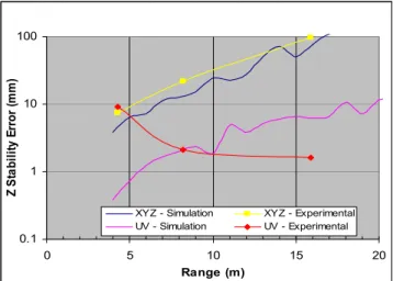
In order to compare the two methods, the targets on the structure shown in Figure 9 were divided in groups and the targets acquired over a period of twelve hours. Standard deviation of the pointing stability for the targets was 40 µrad. Figure 10 shows the results of the object pose model
(simulation) using the previous methods for a 1 m ×1 m array and for the targets of Figure 9. Increased stability/resolution using the photogrammetric model UV, compared to XYZ data is important.
There are several key factors that must be considered when comparing the stability of the pose from the model data and these experimental results, the most important being the distribution of the target, the number, and their sustained angle (size). For the UV method, the distribution of the
targets on the structures was definitely an advantage, providing a larger triangulation base at longer range. The model used a regular target array of 1 m ×1 m, while the experimental data used targets more distributed within the FOV of the laser scanner. The gain is important at longer range for the UV method and almost negligible for the XYZ method. From both the simulated model and
experimental data, an increase in accuracy using resection methods is important.
7 Neptec Space Qualified Laser Camera
The prototype of Figure 2 was obviously not designed to survive the high vibrations levels of the Space Shuttle launch, neither the high temperature fluctuations nor the vacuum of space. Following the successful integration tests between the NRC Laser Tracking System and the Space Vision System, Neptec initiated the development of a space-qualified version of the laser scanner. Figure 11 shows the new Neptec Laser Scanner Camera undergoing vibration testing at Canadian Space Agency David Florida Laboratories. This camera head is fully contained and includes the entire electronics, optics, and laser source, and computers needed for real-time operation. At the time of writing the Laser Camera System was installed in the shuttle payload bay awaiting a scheduled 12 July launch date. The planned on-orbit testing program includes acquisition of both real time tracking data and high-resolution images of elements of the international space station.
Figure 10: Model simulation and experimental results
for analysis of the stability of the pose.
Figure 11. The Neptec Laser
Camera Tracking System under vibration tests at the David Florida Laboratory (photo courtesy Neptec). 0.1 1 10 100 0 5 10 15 20 Range (m) Z St a b ilit y E rr o r ( m m)
XYZ - Simulation XYZ - Experimental UV - Simulation UV - Experimental
Because this new laser scanner system design has been optimized and engineered with the latest state-of-the-art technologies, we are expecting better performances than the one presented in this paper. But experience dictates that the final conclusion will only be available after testing on board the Space Shuttle.
8 Conclusion
This paper has presented some of the research performed toward reaching the objectives of 3D acquisition and tracking of objects in an extremely non-cooperative environment. This work has progressively solved several key questions for a 3D tracking system:
• the demonstration of large volume cooperative target tracking and immunity to sun illumination to analyse the problems of ambient light interferences;
• the understanding of the scanner and the acquisition process dynamics;
• a first demonstration of geometrical object features/target tracking and larger volume calibration;
• the evaluation of the dynamics of object/scanner relative position (moving objects); • the combination of photogrammetry based methods with the laser scanner to increase the
accuracy of the pose evaluation of objects;
• the development of a space qualified version of the laser scanner system.
Using the equivalent virtual pin-hole camera of a 3D laser scanner system, direct compatibility with the collinearity equations model was made possible and an order of magnitude increase in the stability of the pose evaluation method was obtained using photogrammetry methods applied to the laser based scanner system.
References
1. F. Blais, M. Rioux, and J.-A. Beraldin,”Practical Considerations for a Design of a High Precision 3-D Laser Scanner System,” Proc. Soc. Photo-Opt. Instr. Eng. 959, 225-246 (1988). 2. J.-A. Beraldin and al., “Real world modeling through high resolution digital 3D imaging of
objects and structures”, ISPRS Journal of Photogrammetry and Remote Sensing, 55 (2000), 230-250.
3. F. Blais, M. Rioux, and S.G. MacLean, “Intelligent, Variable Resolution Laser Scanner for the Space Vision System,” Proc. Soc. Photo-Opt. Instrum. Eng., 1482, 473-479 (1991).
4. http://www.neptec.com
5. F.Blais, J.-A. Beraldin, L.Cournoyer, I. Christie, R. Serafini, K. Mason, S. McCarthy, C. Goodall., “Integration of a Tracking Laser Range Camera with the Photogrammetry based Space Vision System”, Proceedings of SPIE’s Aerosense 2000 Vol. 4025, p. 219-228, (2000), Orlando, FL.
6. S.G. MacLean, M. Rioux, F. Blais, J. Grodski, P. Milgram, H.F.L. Pinkney, and B.A.
Aikenhead, “Vision System Development in a Space Simulation Laboratory,” Proc. Soc. Photo-Opt. Instrum. Eng., 1394, 8-15 (1990).
7. S.G. MacLean, and H.F.L. Pinkney, “Machine Vision in Space,” Canadian Aeronautics and Space Journal, 39(2), 63-77 (1993).
8. F. Blais, J.-A.Beraldin, S. F. El-Hakim, L. Cournoyer, "Real-time Geometrical Tracking and Pose Estimation using Laser Triangulation and Photogrammetry", 3DIM2001, May 28 - June 1, 2001, Québec City, Canada.