Storage : H
2Production and Small Molecule (CO
2and HX; X =
Cl, Br)
Chemistry
by
Changhoon Lee
B.S. Chemistry, Korea Advanced Institute of Science and Technology, 1998
MASSACHUSETTS INSTITUTE
OF TECHMNOLOGY
SEP
2
8 2011
L iB
RA
R1IF%
ARCHIVES
M.S. Chemistry, Korea Advanced Institute of Science and Technology, 2000
SUBMITTED TO THE DEPARTMENT OF CHEMISTRY IN PARTIAL FULFILLMENT OF THE REQUIREMENTS FOR THE DEGREE OF
DOCTOR OF PHILOSOPHY IN INORGANIC CHEMISTRY AT THE
MASSACHUSETTS INSTITUTE OF TECHNOLOGY September 2011
0 2011 Massachusetts Institute of Technology. All rights reserved.
Signature of Author Department of Chemistry July 5 2011 -I I Certified By Accepted by Daniel G. Nocera The Henry Dreyfus Professor of Energy and Professor of Chemistry Thesis Supervisor
A
-Robert W. Field Haslam and Dewey Professor of Chemistry Chairman, Departmental Committee on Graduate Students
Professor Christopher C. Cummins
Professor of Chemistry Chairman
Professor Daniel G. Nocera
--Henrqy eyfus Professor o'fEnergy and Professor of Chemistry Thesis Supervisor
Professor Richard R. Schrock
Storage : H2 Production and Small Molecule (CO
2 and HX; X = Cl, Br)Chemistry
by
Changhoon Lee
Submitted to the Department of Chemistry on July 5, 2011, in partial fulfillment of the requirements for
the degree of Doctor of Philosophy.
Abstract
The studies in this thesis have focused on the chemistry of transition metal complexes related to solar energy storage: electrochemical H2 production, HX splitting and CO2 activation
mediated by transition metal complexes. Transition metal complexes, for example with macrocyclic ligands, can catalyze electrochemical proton reduction, a half reaction of water splitting to H2/02 by electricity generated by sunlight. The strategy for designing efficient molecular catalysts were explored by introducing a Hangman scaffold into metallomacrocyles. The study exhibits synthesis and electrochemistry of metallomacrocyles, and an example of Hangman effect for electrochemical H2 production. Thermodynamically demanding HX splitting to H2/X2 by sunlight can be a promising method for solar energy storage. To date, most HX
splitting chemistry was studied with metal complexes based on 2"d or 3rd row transition metals. Hence, the usage of cheaper first row metals is an imperative to discover economically viable catalytic systems. HX chemistry of Ni complexes and photoelimination of H2 from Ni hydride complexes, and photoactivation of Ni-Cl bonds were studied. CO2 can be utilized as a carrier of
H2 by the syntheses of liquid fuels from CO2 and H2. The challenge of using CO2 as a precursor
for organic molecules is the activation of strong O=CO bonds. The reaction with metal complexes is one of the methods to break or weaken the bonds. The CO2 chemistry of Ni
complexes was explored, and generation of a new binding mode of CO2 and activation of CO2 to
CO were studied.
Thesis Supervisor: Daniel G. Nocera
Table of contents
Title Page
1
Thesis Committee
3
Abstract
5
Table of Contents
7
List of Figures
12
List of Tables
19
List of Schemes and Charts
20
List of Abbreviations
22
Chapter 1:
Electrochemical H
2Production on Metallomacrocylces
1.1 Introduction
25
1.2 Hydrogen Generation by Hangman Metalloporphyrins
28
Synthesis and Electrochemistry
28
1.3 Synthesis of Modified Tetraazamacrocycles and Hydrogen
37
Synthesis and Electrochemistry
38
1.4
Experimental Section
49
1.4.1
Hydrogen Generation by Hangman Metalloporphyrins
49
Syntheses
49
5-(4-(5-bromo-2,7-di-tert-butyl-9,9-dimethylxanthene))dipyrromethane 49 (6) 5-(4-(5-Bromo-2,7-di-tert-butyl-9,9-dimethylxanthene))- 10,15,20- 50 tris(pentafluorophenyl)-porphyrin (HPX-Br, 2) 5-(4-(5-Bromo-2,7-di-tert-butyl-9,9-dimethylxanthene))-10,15,20- 50 tris(pentafluorophenyl)-porphyrin (HPX-Br, 2) 5-(4-(5-Bromo-2,7-di-tert-butyl-9,9-dimethylxanthene))-10,15,20- 51 tris(pentafluorophenyl)-porphyrinatocobalt (2-Co). 5-(4-(5-Bromo-2,7-di-tert-butyl-9,9-dimethylxanthene))-10,15,20- 52 tris(pentafluorophenyl)-porphyrintozinc (ZnHPX-Br, 2-Zn).Electrochemistry
52
1.4.2
Synthesis
of Modified
Tetraazamacrocycles
and
53
Hydrogen Generation by the Tetraazamacrocycles
Syntheses
54
4-hydroxycarbonyl-5-(4-(2,6-diacetylpyridyl))-2,7-di-tert-butyl-9,9- 54 dimethyl xanthene (7)
4-(3,5-bis(trifluoromethyl)phenyl)-2,6-diacetylpyridine (9)
Co(bpda)(N0 3)2 (bpda = 2,12-dimethyl-3,7,1
1,17-tetraazabicyclo[11.3.1]-heptadeca-1(17),2,11,13,15-pentaene) (10) Hangman Zn(bpda)Br2-H20 (11) Pacman Zn(bpda)Br2 (12) Co(1 5-(3,5-bis(trifluoromethyl)phenyl)-bpda)(N0 3)2 (13) Hangman Co(bpda)(N0 3)2 (14) Pacman Co(bpda)Br2 (15)
Electrochemistry
X-ray Crystallographic Details
Chapter 2:
HX Splitting Chemistry of Ni NHC Complexes
2.1 Introduction
2.2 HX Addition and Photochemical H2 Elimination by Ni NHC
Complexes
Synthesis and Photochemistry
2.3 Photoactivation of Metal-Halogen bonds in a Ni(II) NHC
Complex
2.4 Experimental Section
2.4.1
HX Addition and Photochemical H
2Elimination by Ni
NHC Complexes
Syntheses
Preparation of Ni(H)(Cl)(IMes)2 (1) Preparation of NiCl(IMes)2 (2) Preparation of Ni(H)(Br)Cl(IMes) 2 (3)Photochemistry
X-ray Crystallography
Computational Methods
2.4.2 Photoactivation of Metal-Halogen bonds in a Ni(II) NHC
Complex
Syntheses
Preparation of [Ni(u-C)C1(IPr)]2 (5)
Preparation of NiC12(IPr)(2,6-lutidine) (6)
Photolysis of
5
Treatment of [Ni(IPr)]
2with HCl-dioxane.
Treatment of [Ni(p-Cl)(IPr)]
2with 2,6-lutidine-HCl.
Computational Methods
Chapter 3:
CO
2activation by Ni(O) NHC Complexes
3.1 Introduction
3.2
Generation of a Doubly Bridging CO
2Ligand
and
Deoxygenation of CO
2by an (NHC)Ni(O) Complex
Synthesis and Characterization
3.3 Experimental Section
General Methods
Syntheses
Preparation of [(1,3-bis(2,6-diisopropylphenyl)imidazol-2-ylidene)Ni] 2 (1) Preparation of [(1,3-bis(2,6-diisopropylphenyl)imidazol-2-ylidene)Ni]2(p-CO)(U- r?,r -C02) (2)Preparation of [(1,3-dimesitylimidazol-2-ylidene)Ni] 2(U-CO)(p- rr-,
C0 2) (3)
X-ray Diffraction Studies
111 115 115 121 121 121 121 122 124 124
List of Figures
Chapter 1:
Figure 1.1. CVs of 0.5 mM of 1-Co (-), 2-Co (-), and 2-Co in the presence of 0.5 31
mM benzoic acid (-). Scan rate, 100 mV/s; 0.1 M NBu4PF6 in acetonitrile. Glassy carbon working electrode, Ag/AgNO 3 reference electrode and Pt wire counter
electrode.
Figure 1.2. CV of 2-Zn. Scan rate, 25 mV/s; 0.1 M NBu4PF6 in acetonitrile. Glassy 31
carbon working electrode, Ag/AgNO 3 reference electrode and Pt wire counter
electrode.
Figure 1.3. CV of 0.5 mM 1-Co in the presence of 0 (-), 7.0 (-) and 14.6 mM 32
(-) benzoic acid.
Figure 1.4. CV of 0.5 mM 2-Co in the presence of 0 (-), 7.5 (-) and 15 mM (-) 32
benzoic acid.
Figure 1.5. CV of 7.5 (-) and 15.0 mM (-) benzoic acid. 32 Figure 1.6. CV of 0.5 mM 2-Co in the presence of 0 (-), 7.5 (-) and 15.0 mM 33
(-) benzoic acid.
Figure 1.7. (a) CV of 0.5 mM of 1-Co in the presence of 2.5 mM benzoic acid (-) 34
and 0.5 mM of 2-Co in the presence of 3.0 mM benzoic acid (-). (b) CV of 0.8
mM of 1-Co (-) and 2-Co (-) in the presence of 10 mM tosic acid. Scan rate, 100
mV/s; 0.1 M NBu4PF6 in acetonitrile. Glassy carbon working electrode, Ag/AgNO 3
reference electrode and Pt wire counter electrode.
mM tosic acid.
Figure 1.9. CV of 0.8 mM 2-Co in the presence of 0 (-), 5.0 (-), 10 (-), 20 (-) 35
mM tosic acid.
Figure 1.10. CV of 5.0 (-), 10 (-), 20 (-) mM tosic acid. 35
Figure 1.11. Crystal structure of 7 showing thermal ellipsoids at 50% probability. 39
Disordered atoms and protons are omitted for clarity.
Figure 1.12. Crystal structure of 8 showing thermal ellipsoids at 50% probability. 40
Disordered atoms and protons are omitted for clarity
Figure 1.13. Crystal structure of 10 showing thermal ellipsoids at 50% probability. 40
Disordered components and protons are omitted for clarity.
Figure 1.14. Crystal structure of 12 showing thermal ellipsoids at 50% probability. 41
Solvents, protons and two bromide anions are omitted for clarity.
Figure 1.15. Cyclic voltammograms of 1 mM of 10 in 0.1 M NBu4PF6 acetonitrile 42
solution at 0 (-), 4.8 (-), 8.0 (-), 12.0 (-) mM of tosic acid. (Top) The plot of
ie/ip vs [tosic acid] . (Bottom) Scan rate: 100 mV/s. Glassy carbon working electrode (0.07 cm2) and Ag/AgNO
3 reference electrodes.
Figure 1.16. UV-vis spectra of the sample containing 10 obtained before and after 43
bulk electrolysis in the presence of tosic acid.
Figure 1.17. Cyclic voltammograms of f 10 in 0.1 M NBu4PF6 and 20 mM tosic 44
acid acetonitrile solution at 0.25 (-), 0.5 (-), 0.71 (-), 1.0 (-) mM of 4. The plot
of i, vs catalyst concentrations. Scan rate: 100 mV/s. Glassy carbon working electrode and Ag/AgNO3 reference electrode.
0 (-), 25 (-), 50 (-), 75 (-), 100 s (-) from the initiation. Pt working and
Ag/AgNO 3 reference.
Figure 1.19. UV-vis spectra of Col(bpda)* (10), Co"(bpda)2+ and reaction mixture of 45 Co'(bpda)* and tosic acid.
Figure 1.20. Cyclic voltammograms of 1 mM of 13 in 0.1 M NBu4PF6 acetonitrile 45
solution at 0 (-), 3.0 (-), 4.0 (-), 5.0 (-), 6.0 (-) mM of triflic acid. Scan rate: 100 mV/s. Glassy carbon working electrode (0.07 cm2) and Ag/AgNO
3 reference
electrodes.
Figure 1.21. Cyclic voltammograms of 1 mM of 14 in 0.1 M NBu4PF6 acetonitrile 46
solution at 0 (-), 2.0 (-), 3.2 (-), 6.4 (-), 9.6 (-) mM of tosic acid. Scan rate: 100 mV/s. Glassy carbon working electrode (0.07 cm2) and Ag/AgNO
3 reference
electrodes.
Figure 1.22. UV-vis spectra of Hangman Co', Hangman Co" (14) and reaction 47 mixture of Co, and tosic acid.
Figure 1.23. UV-vis spectra of the sample containing 14 obtained before and after 47 bulk electrolysis in the presence of tosic acid.
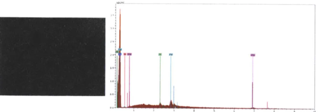
Figure 1.24. SEM and EDX analyses of glassy carbon plate after bulkelectrolysis of 48
14 in the presence of tosic acid.
Chapter 2:
Figure 2.1. Examples of complexes for photoelimination of halogen. 73
Figure 2.2. Thermal ellipsoid plots of 1 (top) and 2 (bottom) at the 50% probability 75
Figure 2.3. Thermal ellipsoid plots of 3 (top) and 4 (bottom) at the 50% probability 76
level. Hydrogen atoms have been omitted for clarity. A bromide from disorder in the crystal is also omitted for clarity.
Figure 2.4. Comparison of UV-vis spectrum of 1 (-) and 2 (-) in toluene. 77
Figure 2.5. Comparison of UV-vis spectrum of 1 (-) in THF and calculated 78
transitions (bars). The red and blue bars correspond to transitions that are color coded in Figure 2.6.
Figure 2.6. Energy diagram of the orbitals of the model complex involved in the 79
most intense electronic transitions above 290 nm. Transitions indicated by blue and red lines correspond to the excitations calculated at 297 nm (blue) and 366 nm (red). The red bars of the MO picture correspond to the red transition of Figure 2.5 and likewise for blue.
Figure 2.7. X-ray crystal structure of 5 from a single crystal grown in 82
toluene/hexanes. Thermal ellipsoids are shown in 50 % probability. Hydrogen atoms are omitted for clarity.
Figure 2.8. X-ray crystal structure of 5 from a single crystal grown in 82
dichloromethane/pentane. Thermal ellipsoids are shown in 50 % probability. Hydrogen atoms, solvent and chloride atoms from a disorder due to tetrahedral distortion are omitted for clarity.
Figure 2.9. UV-vis spectrum of 1 (-) in toluene, calculated transitions (red bars) of 83
1-S,
and selected molecular orbitals involved in calculated transitions.Figure 2.10. X-ray crystal structure of 6. Thermal ellipsoids are shown at 50 % 84
Figure 2.11. UV-vis spectra of [Ni(p-Cl)(IPr)]2 in benzene (-) and 5 in toluene (-) 97
(left). Photolysis of 5 in toluene with >295 nm light (right).
Figure 2.12. The list of occupied orbitals involved in calculated transitions between 100
360.39-301.40 nm
Chapter 3:
Figure 3.1. Examples of CO2 activation resulting in CO and metal oxo species by 112
metal complexes
Figure 3.2A. The molecular structure of 1 showing thermal ellipsoids at 50% 116
probability. The solvent molecules are omitted for clarity.
Figure 3.2B. (a) 1H NMR spectrum of 1 in C6D6. (b) 'H NMR spectrum of 1 after 116
one week at 45 C.
Figure 3.3. The molecular structure of 2 showing thermal ellipsoids at 50% 117
probability.
Figure 3.4A. 13C NMR spectrum of 2 prepared using 13C0 2 showing resonances of 118 p-CO and p- r, e-CO 2
.
Insets show the splitting of each resonance.Figure 3.4B. IR spectra of 2 and 2 prepared using 13C02 showing shift of bands 118
corresponding to p-CO and p-rf,re-CO2
.
Figure 3.5A. 13C NMR spectrum of 3 prepared using 13C0 2 showing resonances of 119
p-CO and p- r, r-CO2. Insets show the splitting of each resonance.
Figure 3.5B. IR spectra of 3 and 3 prepared using 13C02 showing shift of bands 119
Figure 3.6. The molecular structure of 3 showing thermal ellipsoids at 50% 120
List of Tables
Chapter 1:
Table 1.1. Crystal Data and
Table 1.2. Crystal Data and
Table 1.3. Crystal Data and
Table 1.4. Crystal Data and
Chapter 2:
Table 2.1. Table 2.2. Table 2.3. Table 2.4. Table 2.5. Table 2.6. Table 2.7. Table 2.8. Structure Structure Structure Structure Refinement for 7. Refinement for 8. Refinement for 10. Refinement for 12.Crystal Data and Structure Refinement for 1. Crystal Data and Structure Refinement for 2. Crystal Data and Structure Refinement for 3. Crystal Data and Structure Refinement for 4.
Cartesian coordinates of calculated optimized geometry for 1-CH3.
Crystal Data and Structure Refinement for 5.
Crystal Data and Structure Refinement for 5-CH2Cl2.
Crystal Data and Structure Refinement for 6.
90 91 92 93 94 101 102 103 104
Table 2.9. Cartesian coordinates of calculated optimized geometry for 5-S.
Chapter 3:
Table Table Table 3.1. 3.2. 3.3.Crystal Data and Structure Refinement for 1. Crystal Data and Structure Refinement for 2. Crystal Data and Structure Refinement for 3.
126
127
List of Schemes and Charts
Chapter 1:
Chart 1.1. Examples of molecular proton reduction catalysts 27
Scheme 1.1. Mechanism of metal complex mediated electrochemical H2 production 29
Chart 1.2. Structures of CoHPX-CO2H and CoHPX-Br 29
Scheme 1.2A. Statistical Synthesis of 2-Co 30
Scheme 1.2B. Synthesis of 6 30
Scheme 1.2C. Rational Synthesis of 2-Co 30
Scheme 1.3. Mechanism of H2 production from benzoic acid mediated by 1-Co and 34
2-Co
Chart 1.3. Structures of 10-15 37
Scheme 1.4. Syntheses of 7, 9, 11, 13 and 14 38
Scheme 1.5. Syntheses of 8, 12 and 15 39
Chapter 2:
Scheme 2.1. Possible catalytic cycle for HX splitting 72
Scheme 2.2. Reaction Schemes of HX splitting by Ni(IMes)2 and subquent H2 74
generation reactions.
Scheme 2.3. Reaction Schemes of HX reactions and photoreactions 85
Chart 3.1. Binding Modes of CO2ligand 112
Scheme 3.1A. Homogeneous catalytic deoxygenation of CO2 113
Scheme 3.1B. Ligand based reduction of CO2 to CO 114
br calcd.
cm-1
CV d DFT e EDX ESI Et equiv Fc g h HER HOMO HRMS Hz IR broad calculated wavenumber cyclic voltamm doublet density functio electron energy dispersi electrospray io ethyl equivalent ferrocene gram hour hydrogen evolu highest occupie high resolution hertz infra red coupling constList of Abbreviations
LD-MS laser des LUMO lowest u Lut lutidine ogram m multiple MALDI matrix-asnal theory mg milligrai
mL milliliter
ve X-ray analysis min minutes
nization NHC N-hetero NMR nuclear OAc acetate OTf trifluoro s singlet SEM scanning
tion reaction t triplet
d molecular orbital tert tertiary
mass spectrometry tosic p-tolueni
vis visible
6 chemica
ant a extinctio
orption mass spectrometry noccupied molecular orbital
t
sisted laser desorption/ionization
cyclic carbene nagnetic resonance methylsulfonate electron microscopy esulfonic l shift n coefficient
Chapter 1. Electrochemical H2 Production on Metallomacrocylces
Portions of this have been published:
(1) Lee, C. H.; Dogutan, D. K.; Nocera, D. G. J. Am. Chem. Soc, 2011, 133, 8775-8777.
1.1
Introduction
The worldwide energy consumption rate in 2007 was 16.2 TW and, because of economic growth and rising standards of living of a growing world population, the energy demand is expected to double by 2050 and triple by 2100.1,2 Currently, our energy supplies mostly rely on burning fossil fuels and it is suggested that the amount of oil, natural gas and coal in the reserves will meet this energy need.' However, the combustion of fossil fuels has been contributing to accumulation of green house gases in the atmosphere by emitting
CO
2.
Moreover, because there are no natural pathways for CO2 decomposition, the emitted CO2 will remain in the atmospherefor a long period of time. The current CO2 concentration of 380 ppm in the atmosphere is
significantly higher than those in last 0.65 million years. Hence, staying reliant on burning fossil fuels at current rate might cause a significant global climate issues such as global warming, sea level rises and permafrost loss.
To suppress the increase of CO2 level in the atmosphere, the development of CO2
capturing and sequestration technologies is needed and, more importantly, drastic change in energy supply from fossil fuels to carbon neutral energy sources is urgent. Nuclear fission and biomass are the ways of avoiding additional CO2 emission. However, those methods are limited due to slow rate of construction of nuclear power plants and low energy efficiency of photosynthesis,3 and not sufficient enough to keep up the growing energy demand. Among the other energy sources, the sun is the largest renewable carbon neutral energy source. The energy from the sun provided per 1 hr is more than the energy consumption on the world in 1 yr.'
To harness energy from the sun, technologies converting solar energy to utilizable forms are needed and, because we need continuous energy supply to support our everyday life, viable means of storing the energy for dark hour usage is also very important. Sunlight can be captured and converted to electricity by photovoltaics, though electricity produced through photovoltaics is still not as cost-effective as that derived from fossil fuels and the developments for decrease of manufacturing cost is required. Even if we have the technology to produce electricity from sunlight cost-effectively, however, without the technologies to store that electricity, continuous energy supply cannot be achieved, because sunlight is not available 24 hours a day.
Solar energy could be stored in compressed air, flywheels, super capacitors, pumped water or batteries.3 In considering energy densities, they are, however, impractical for large amounts of energy storage due to low energy densities in those storage forms.3,4 The other
method of storing solar energy is the production of fuels possessing high energy chemical bonds through thermodynamically uphill reactions driven by sunlight, analogous to how nature captures and stores solar energy through photosynthesis. This method will enable very dense energy storage in chemical bonds.4'5 For example, by splitting water to H2 and 02, an energy of 140 MJ
can be stored in 1 kg of H2.4
The storage of solar energy for dark hour usage could be realized by electrolyzing water to produce H2 and 02 using electricity generated by photovoltaics. The H2 could be used in fuel cells to release the stored solar energy when the sunlight is not available.1,3 An electrochemical cell designed by Turner et al. exhibits such a system with photoelectrochemical-photovoltaic design harvesting solar energy through electrolysis of water with high efficiency.6 In the cell, oxygen and protons are generated at platinum electrode and protons are reduced to hydrogen at a photoactive semiconductor. However, the usage of expensive electrode materials like platinum, of which reservoirs are not enough for world wide application of the cell design, is the problem of this system. Thus, it has been the imperative to discover cheap catalytic system for practical applications. A catalytic system composed of cobalt and phosphate, which splits water into oxygen and protons at neutral pH with low overpotential, has been discovered recently by our group7 and the next step will be to couple such a system with cheap and economically viable proton reduction catalysts.
Interest in cost-effective proton reduction catalysts replacing precious metal electrodes has led to the studies of hydrogen evolution reaction (HER) with metal electrodes. However, the research indicated that precious metals, particularly platinum, are the most active in hydrogen evolution reaction.3 Nature has enzymes called hydrogenases, operating near the thermodynamic potential for H2 activation and generation. They usually contain iron or nickel as metal components. Inspired by nature's enzymes, metal complexes based on earth abundant first row transition metals including model complexes of hydrogenase 8-10 and macrocycles have been
studied for hydrogen evolution reaction. 1-23
Complexes with macrocyclic or chelating ligands are attracting attention due to stability of the complexes imparted by the chelate effect. For example, first row metal based metalloporphyrins (e.g. chart 1.1 A)2
0-2 3, metallo-diglyoximes(e.g. B)15-19 and complexes with
chelating ligand (e.g. C)"'1'14 were studied and are now well known to catalyze proton reduction. Cobalt diglyoximes catalyze proton reduction at promisingly low overpotential (e.g.
Co(dmgBF2)(CH3CN)2 (dmgBF2 = difluoroboryldimethlyglyoxime)).16 The complex C has the design of incorporating internal bases taking advantage of proton relay by pendant base group." Porphyrins with iron , cobalt20,21 and rhodium2 as central metal atoms are also known to catalyze proton reduction.
Chart 1.1 I N Fe N A Me C F2 N C Me B Ph Ph Ph Ph N Ni Ph \~~ P Ni, "" P Ph Ph Ph C
1.2
Hydrogen Generation by Hangman Metalloporphyrins
A particularly fascinating design element of emergent catalysts is the incorporation of a
proton relay from a pendant acid-base group proximate to the metal center where H2 production occurs. 1-13,24-27 These catalysts are akin to the active sites of hydrogenases, which feature pendant bases positioned near the metal centers that are postulated to play a role in enzyme catalysis.2 8 The benefits of a pendant proton relay are consistent with the early proposal of H
2
generation via the pathway shown in Scheme 1.1 A: reduction of a Cor center to Col followed by H* attack to yield a hydridic Co"H species that yields H2 upon protonolysis or bimetallic reaction. However, this mechanism has been recently re-considered in view of the contention that Co1H centers are not sufficiently basic to drive protonolysis. Accordingly, the suggestion has been made that more reduced cobalt species must be attained before protonolysis can occur (Scheme 1.1B).29,30 The inability to control proton stoichiometry in most catalytic cycles has
made it difficult to distinguish mechanisms and thus discern which intermediate is involved in catalysis. On this count, we realized the utility of hangman active sites for providing insight into the mechanism of H2 evolution by stoichiometric generation of a key intermediate as a result of the hangman effect. In the hangman construction, an acid-base functionality is positioned from a xanthene or furan spacer over the face of a redox-active macrocycle such as porphyrin,3 1 3 2 salen3 3
,3 4 or corrole.35 The acid-base hanging group permits the facile transfer of a single proton to or from a substrate bound to metal macrocycle. With the ability to control proton stoichiometry from the hanging group, we undertook studies to examine H2 generation at
CoHPX-CO2H (1-Co) shown in Chart 1.2. Comparison of the electrochemistry of 1-Co to a
macrocyclic analog in which the hanging group has been removed CoHPX-Br (2-Co, Chart 1.2) establishes the hangman effect (via a reduced overpotential) and that the Co center produces H2 only beyond reduction potentials exceeding the Col oxidation state. Our results are consistent with the generation of Co"H as a key intermediate in H2 electrocatalysis at the hangman cobalt porphyrin active sites.
Synthesis and Electrochemistry
We recently published an efficient synthesis for hangman porphyrins bearing a pendant carboxylic acid group under microwave irradiation.3 6 The new procedure allows us to obtain hangman porphyrins in multimilligram quantities, in shorter synthesis time, and with much better
Scheme 1.1 Co(II) + e -- Co(I) Co(I) + H-+ Co(III)H
(A)
Co(II)H + H+ -+ Co(Ill) + H22Co(III)H
-2Co(II)
+ H2(B)
Co(III)H + e - Co(II)H or Co(II)H + H- Co(II) + H 2yields. The new hagman library was synthesized with various substituents on the 5, 10, 15 meso positions. Cobalt (II) complexes of hangman porphyrins bearing electron withdrawing (pentafluorophenyl, 3,5-bis-trifluoromethylphenyl), electron releasing (4-methoxyphenyl, 4-tert-butylphenyl), bulky (2,4,6-trimethylphenyl) and alkyl (pentyl) substituents were delivered in workable amounts. The good yields in the porphyrin forming reaction and easy purification of the crude reaction mixture allowed us to structurally characterize the new hangman porphyrin library.36,37 In this study we synthesized a new A3B type of hangman porphyrin bearing a bromine (CoHPX-Br, 2-Co) instead of carboxylic acid to emphasize the key advantage of
Chart 1.2 tBu O H C6F5 / \ CoN- C6F5 tBuN N C6F5 CoHPX-CO2H (1-Co) tBu \Br 0 C6F5 N 'Co'..-- CF5 tBuN N CHPXBr( -Co CoHPX-Br (2-Co)
having proton donating group for electrochemical H+ reduction.
The synthesis of 2-Co was accomplished with two different routes. In route 1, statistical Lindsey porphyrin synthesis38 was performed by condensing pentafluorobenzaldeyhde with xanthene aldehyde (3)39 and excess pyrrrole in the presence of BF3.EOt2. The reaction afforded the corresponding A3B (A = pentafluorophenyl, B = xanthene backbone) porphyrinogen in situ.
Scheme 1.2A
'Bu
0 F / \ Br 1) (a) BF3.OEt2, CHC13 (b) DDQ
H F -~ 2) Co(OAc)2, CHCl3:MeOH (3:1)
N + 0+" 2-CO
' F F - 34% for two steps-porphyrin F \ / formation and metallation
H tBu 3 Scheme 1.2B 'Bu / Br tBu tBu + InC 3 O N - 080% x Br H H NH HN tBu 3 6 Scheme 1.2C F F F F O F F 1) MesMgBr (2.5 equiv, 1.0 M, THF) F F F H nC13 0 *C, toluene F F N HNH HN F F 46% 2) F O F NH HN F C ,TO*, 69% - O O 4 F F F F 5 F F F F F F F F u B
F F tBu tBu 1)Sc(OTf)3, CH2CI2, DDQ
NaBH4, THF/MeOH \ FI H F | 0 2) Co(OAc)2, CHC3:MeOH
2-Co
quantitative F/ \ N Br 31% for two step
- OH HO F NH HN porphyrin formation and
F F 5-OH F F metallation
delivered the free-base HPX-Br (2) in 38% isolated yield. Metallation of 2 with Co(OAc)2 under microwave irradiation gave 2-Co in 34% overall chemical yield (Scheme 1.2A).
The lengthy purification of the 2 with flash column chromatography (3 days, see experimental section) encouraged us to try the synthesis of the target porphyrin in stepwise fashion. In route 2, the 1,9-diacyldipyrromethane (5) and a new dipyrromethane (6) (Scheme 1.2B) were synthesized by modifying the published procedures.36'40 In situ reduction of 5 with excess NaBH4 afforded the corresponding 1,9-diacyldipyrromethane dicarbinol, 5-OH in quantitative yield. Lewis acid catalyzed condensation of the latter with the second dipyrromethane 6 was followed with in situ DDQ oxidation. The fast filtration of the crude
S pA
I I I I I I I I 1
-0.5
-1.0
-1.5
-2.0
-2.5
E vs ferrocene (V)
Figure 1.1. CVs of 0.5 mM of 1-Co (-), 2-Co (-), and 2-Co in the presence of 0.5 mM benzoic acid (-). Scan rate, 100 mV/s; 0.1 M NBu4PF6 in acetonitrile. Glassy carbon working electrode, Ag/AgNO 3 reference electrode and Pt wire counter electrode.
reaction mixture through a pad of silica afforded free-base porphyrin 2 in 32% isolated yield. Final metallation of the title compound with Co(OAc)2 under microwave irradiation afforded
2-Co in 31% over all yield (Scheme 1.2C). Although the stepwise synthesis of 2-2-Co has three
additional steps (synthesis of compounds 4, 5, and 6) versus statistical synthesis, easy purification of the free-base porphyrin 2 (2h versus 3 days) makes this route more attractive.
As shown in Figure 1.1, 1-Co and 2-Co exhibit reversible waves for the Corn couple at almost the same potentials (-1.08 V vs the ferrocene/ferrocenium couple for 1-Co and -1.10 V for 2-Co). The cyclic voltammogram (CV) of 2-Zn shows redox waves at -1.52 and -1.92 V (Figure 1.2), and confirms that each electrochemical feature of 1-Co and 2-Co has significant cobalt character. For simplicity, the reduction potentials will be formally ascribed to Co, though we believe that there is significant electron density on the porphyrin ring at very reducing potentials.
1 A
-1.0 -1.4 -1.8 -2.2
E vs ferrocene (V)
Figure 1.2. CV of 2-Zn. Scan rate, 25 mV/s; 0.1 M NBu4PF6 in acetonitrile. Glassy carbon working electrode, Ag/AgNO3 reference electrode and Pt wire counter electrode.
I25
pA
I I I I I I I0.0 -0.5 -1.0 -1.5
E vs ferrocene
1 I
-2.0
(V)
i i-2.5
Figure 1.3. CV of 0.5 mM 1-Co in the presence of 0 (-), 7.0 (-) and 14.6 mM (-) benzoic acid.
I30
pA
L I I I I I I I I I I
0.0 -0.5 -1.0 -1.5 -2.0 -2.5
E vs ferrocene (V)
Figure 1.4. CV of 0.5 mM 2-Co in the presence of 0 (-),
7.5 (-) and 15 mM (-) benzoic acid.
125
pA
-2.5
Figure 1.5. CV of 7.5 (-) and 15.0 mM (-) benzoic acid. I A I I I I - a 1
0.0 -0.5 -1.0 -1.5 -2.0
Whereas 2-Co shows a reversible wave for Co"0 at -2.14 V, interestingly, 1-Co produces an irreversible wave for the reduction of Col and the wave is positively shifted by -200 mV. The only structural difference between 1-Co and 2-Co is the hanging carboxylic acid group and accordingly the irreversible process of 1-Co is ascribed to the hangman effect where the reduction of Co' to Coo is followed by immediate proton transfer from the hanging group to produce Co"H. The second wave in the CV of 2-Co also becomes irreversible upon the addition of external benzoic acid. At 1 equiv of benzoic acid, the wave begins to exhibit irreversibility, also indicating protonation of the Coo species. Complete irreversibility of the wave is observed only upon addition of >1 equiv of benzoic acid; this observation is also consistent with the hangman effect in 1-Co.
In the presence of excess benzoic acid (pKa = 20.7 in acetonitrile),4
1 1-Co and 2-Co
exhibit catalytic cathodic waves (Figures 1.3, 1.4 and 1.7a). Although the overpotential for catalysis is large (-800 mV), the catalysis performance is not our interest; the CV features of the electrocatalysis uncover essential mechanistic details of HER at cobalt porphyrins and the effect of dangling acid group. The ComUI reduction feature is not affected much by the presence of acid (Figure 1.3, 1.4 and 1.6) but the second reduction wave exhibits pronounced catalytic activity. These results indicate that benzoic acid is too weak an acid to protonate the Co' center, and hence catalytic H2 production is observed only upon further reduction to Coo (Scheme 1.3). The overpotential for proton reduction of 1-Co is ~120 mV lower potential than that of 2-Co at 3 mM acid concentration. Moreover, the potential of the second reduction wave of 1-Co is the same in the presence and absence of acid (Figure 1.3). This is not the case for 2-Co; with increasing acid concentration the wave shifts to higher potential by 80 mV (Figure 1.4). These results are also
I I I I I I I I I
0.0
-0.5
-1.0
-1.5
-2.0
E vs ferrocene (V)
Figure 1.6. CV of 0.5 mM 2-Co in the presence of 0
(a)
(b)
110
pA
120pA
I i I i I a I a I I . I a I a I
-0.5 -1.0 -1.5 -2.0 -2.5 -0.5
-1.0
-1.5
-2.0
E vs ferrocene (V)
E vs ferrocene (V)
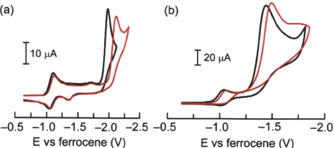
Figure 1.7. (a) CV of 0.5 mM of 1-Co in the presence of 2.5 mM benzoic acid (-) and 0.5 mM of 2-Co in the presence of 3.0 mM benzoic acid (-). (b) CV of 0.8 mM of 1-Co (-) and 2-Co (-) in the presence of 10 mM tosic acid. Scan rate, 100 mV/s; 0.1 M NBu4PF6 in acetonitrile. Glassy carbon working electrode, Ag/AgNO3 reference electrode and Pt wire counter electrode.
Scheme 1.3
Co(I1) + e- b Co(I)
Co(I) + e- Co(0)
Co(0)
+ H+ Co(II)HCo(II)H + H* -- Co(11) + H2
indicative of the hangman effect since in 1-Co, proton transfer is not rate-determining for catalysis (hence the insensitivity of the reduction wave to proton concentration) whereas in 2-Co, the proton transfer is a determinant of the mechanism (hence the shift to more positive potential with increasing acid). For either case, H2 catalysis is initiated from the CorH.
Bulk electrolysis was performed in acetonitrile solutions of 0.4 mM 1-Co at -2.05 V and of 0.5 mM 2-Co at -2.20 V in the presence of 15 mM benzoic acid. The amount of H2 gas produced during the electrolysis was determined by gas chromatography after 15 C of charges had passed. Faradaic efficiencies for H2 production were ca. 80% and 85% for 1-Co and 2-Co, respectively; no other gaseous product is detected in the experimental condition. On the basis of
TLC, mass spectra and UV-vis measurements, the decomposed product in bulk electrolysis in the
I50pA
-0
I a I a I i
.5 -1.0 -1.5 -2 .0
E vs ferrocene (V)
Figure 1.8. CV of 0.8 mM 1-Co in the presence of 0 (-),
5.0 (-), 10 (-), 20 (-) mM tosic acid.
I50
pA
-0.5 -1.0 -1.5 -1 -2.0E vs ferrocene (V)
Figure 1.9. CV of 0.8 mM 2-Co in the presence of 0 (-),
5.0 (-), 10 (-), 20 (-) mM tosic acid.
50 pA
I I I a I a 1 .5 -1.0 -1.5 -2.E vs ferrocene (V)
Figure 1.10. CV of 5.0 (-), 10 (-), 20 acid. (-) mM tosic -0 0In the presence of the stronger tosic acid (p-toluenesulfonic acid, pKa = 8.3 in
acetonitrile),41 both 1-Co and 2-Co exhibit catalytic cathodic waves at ~ -1.5 V (Figures 1.7b,
1.8 and 1.9). The similarity of the CVs with regard to current and the onset of electrocatalysis
suggest that the stronger acid overwhelms the chemistry of the system and the hangman effect is diminished. As observed for benzoic acid, electrocatalysis for 1-Co and 2-Co occurs at potentials negative of the Co"" couple. However, there is one significant difference between the benzoic acid and tosic acid data; unlike the situation for benzoic acid, the Col'i wave becomes irreversible in the stronger tosic acid for both 1-Co and 2-Co (Figures 1.7b, 1.8 and 1.9). This indicates that Col is protonated by the tosic acid. But the observation that catalysis occurs well past the Co"I" reduction event indicates that a Co"H species, when formed, needs to be further reduced to Co"H for H2 generation to occur. One determinant of the metal basicity is the presence of meso groups on macrocycle periphery. The electron withdrawing C6F5 groups will attenuate the metal center basicity and make the metal less reactive to protons, as has previously
been observed.16,4 2
In summary, the hangman porphyrin provides mechanistic insight into H* reduction owing to the ability to control proton equivalency precisely via the hanging group. The irreversibility and positive shift of the reduction of Col in 1-Co together with a lowered overpotential for H2 production are a result of the hangman effect. For the case of weak acids, H2 is produced upon reduction to Coo followed by protonation (Scheme 1.3). For stronger acids, Col is first protonated and electron reduction follows it (Scheme 1.1 B). Regardless of the strength of the acid, these results are consistent with H2 production being mediated by Co"H. Further reduction of the metal is needed for the effective protonation of the hydride to produce H2.
1.3
Synthesis
of Modified Tetraazamacrocycles
and Hydrogen
Generation by the Tetraazamacrocycles.
Modification on macrocyclic ligand framework aiming at tuning the properties of complexes has been one of the main topics in inorganic chemistry. Our group has invented the Hangman concept to faithfully capture the distal function of the enzymes such as hydrogenases and oxygenases.31-35 Also, our group has reported cofacial bisporphyrins providing the Pacman effect in a single framework.4 3 Inspired by our previous results, we decided to prepare analogues of modified porphyrins with different macrocyclic ligand, bpda (2,12-dimethyl-3,7,11,17-tetraazabicyclo[11.3.1]heptadeca-1(17),2,11,13,15-pentane, bisiminopyridylamine) and utilize some of the Co macrocyclic complexes for electrochemical 112 production in order to understand the effect of functionalities introduced into the macrocycle on the ability of H2 production. Among reported synthetic macrocyclic ligands, bpda ligand is one of the most extensively studied ligands since Busch et al. reported synthesis of Ni(bpda)Br2.4 Also, Co(bpda)Br2 catalyzes the electro- and photoelectrochemical reduction of CO2 in the presence of H* to
produce CO with H2 as side product.45 In this work, we report derivatives of diacetylpyridine, 7 and 8 along with 9 which were prepared by Suzuki coupling following borylation reaction, and
Chart 1.3 tBu - 0 OH 2+ lo* O 2+ /N-,Co-N \ / 'N-M-N tBu 10 11: M = Zn 14: M= Co tBu 4+ N-M-N --N 72+ It. F3C N N N-M-N /-CoN tBu F3C 12: M = Zn 13 15: M= Co
macrocyclic compounds with modified ligand framework, 11-15, which were prepared by template reaction of the derivatives and 3,3'-diaminodipropylamine in the presence of Zn2+ or
Co2+ (Scheme 1.4 and 1.5).
It turned out that the Co complex 10 is a stable electrocatalyst for H2 generation. The
Co"i" reduction potential can be positively shifted with the addition of electron withdrawing
groups on the 13. However, this electronic perturbation given by an electron-withdrawing group hinders proton reduction. The electrochemistry of Hangman complex 14 was complicated by putative palladium impurities from coupling reaction reagents.
Synthesis and Electrochemistry
Derivatives of diacetylpyridine were obtained according to Scheme 1.4 and 1.5 by Suzuki coupling reactions following iridium catalyzed borylation of the 4-position of the pyridine moiety. The methods of borylation of heteroarenes based on iridium catalysts have been developed by Ishiyama, Miyaura and Hartwig et. al.,46'47 and we utilized [Ir(OMe)(COD)]
2
(COD = cyclooctadiene) as a precatalyst for the borylation of diacetylpyridine in the presence of
dtbpy (4,4'-Di-tert-butyl-bipyridyl). After the borylation reaction, volatile materials were
removed from the reaction mixture and the reagents for Suzuki coupling reaction were added to
Scheme 1.4 O B Ar 11 a b o(N) o HB N +
a
0 0 Ar + YN-M--H2N N.- NH2 c Ar N- X2 0 0 t-Bu CO2H F3C 7, 11 and 14: Ar = 0 H 9 and 13: Ar = F3C t-Bua [Ir(OMe)(COD)]2, 2dtbpy, cyclohexane, 100 'C. b Ar-Br, Pd(PPh3)4, Na2CO3, H20, DMF,
90 'C. c 11 : ZnBr2, 7, methanol, 1,2-dichloroethane and 60 *C , 13 : Co(N0 3)2-6H20, 9,
Scheme 1.5 0 0 t-Bu O'B'O ' N 0 b N) 0 O N 0 0 t-Bu t-Bu t-Bu \ N HcN -M 2NO N 2 - NH2 O Br4 - N N--N t-Bu - t-Bu
a [Ir(OMe)(COD)]2, 2dtbpy, cyclohexane, 100 *C. b 4,5-dibromo-2,7-di-tert-butyl-9,9-dimethylxanthene, Pd(PPh3)4, Na2CO3, H20, DMF, 90 *C. c 12 : ZnBr2, 8, methanol,
1,2-dichloroethane and 60 'C , 15 : CoBr2, 8, ethanol, 1,2-dichloroethane and 70 *C.
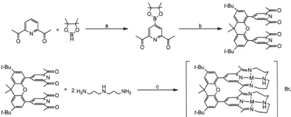
the flask without isolation of the borylated product. Each compound was purified by column chromatography and characterized by NMR spectroscopy, mass spectrometry and elemental analysis. Compound 7 and 8 were structurally characterized by X-ray crystallography, and functionalization of 4-position diacetylpyridine was confinmed (Figure 1.11 and 1.12).
Metal complexes were prepared by metal templated reactions of the derivatized diacetylpyridines and 3,3'-diaminodipropylamine in the presence of metal salts and purified by
(QC(13)
0(2A)
0(3A)
Figure 1.11. Crystal structure of 7 showing thermal ellipsoids at 50% probability.
Figure 1.12. Crystal structure of 8 showing thermal ellipsoids at 50% probability.
Disordered atoms and hydrogen atoms are omitted for clarity
recrystallization (Scheme 1.4 and 1.5). The macrocyclic complex 10 prepared this way according to the literature48 was purified by recrystallization from acetonitrile solution. It was characterized
by X-ray crystallography (Figure 1.13) and elemental analysis. In the literature, the complex was
crystallized upon the cooling of concentrated reaction mixutre and hydrated crystals were formed.48 O(3B) O(2A) ( C(7) C(3) C(2A) C(5A)
Figure 1.13. Crystal structure of 10 showing thermal ellipsoids at 50% probability.
Disordered components and hydrogen atoms are omitted for clarity.
The 1H NMR spectrum of 11 shows singlets at 1.36, 1.43 ppm for tert-butyl protons and
1.75 ppm for methyl protons on xanthene spacer, and two overlapped singlets at 2.66 ppm for
protons of methyl groups on the imine carbons. The protons on aromatic rings of xanthene spacer shows doublets at 7.52 - 7.76 ppm and the protons on the pyridine ring shows singlet at 8.57
ppm. The protons on dipropylamine linker show multiplets at 1.83 - 4.26 ppm. The MALDI mass analysis agrees with the structure with hangman scaffold and it is confirmed that the complex is isolated as hydrated form by elemental analysis.
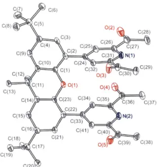
Single crystal of 12 was obtained by slow diffusion of Et2O into methanol solution of crude product. As shown in Figure 1.14, the crystal structure of 12 confirms cofacial nature of two macrocycles containing Zn atoms. Contrary to 10 which has the metal center in octahedral geometry where 4 nitrogen atoms form rather square planar structure (Figure 1.13), each metal center in 12 has distorted square pyramidal geometry with one bromide coordinated to the metal. The distance between two Zn metals is 6.259
A.
The 'H NMR spectrum of 12 shows singlets at1.38 ppm for tert-butyl protons, 1.81 ppm for methyl protons on xanthene spacer and 2.23 ppm
for protons of methyl group on the imine carbons. The protons on aromatic rings of xanthene spacer are found as two doublets at 7.34 and 7.68 ppm and the protons on the pyridine ring are
N(2) N(3) N(1) Zn(1) N(4) Br(1) Br(2) N(6) (5) zn(2) N(8) N(7)
Figure 1.14. Crystal structure of 12 showing thermal ellipsoids at 50% probability.
found as singlet at 8.10 ppm. The protons on dipropylamine linker are found as multiplets at 2.05
- 4.31 ppm. The spectrum shows some small signals besides the major signals corresponding to
the structure. However, the sample was pure by elemental analysis, therefore these signals seem to be originated from small amount of conformers generated by rotation of macrocycles or
flipping of dipropylamine linker.
The complex 13, 14, and 15 were prepared in a similar way and characterized by mass
spectrometry. ESI mass analyses agree with the expected macrocyclic structure of the complexes. Complex 13 was isolated as analytically pure crystals from acetonitrile solution by layering diethyl ether.
20
pA
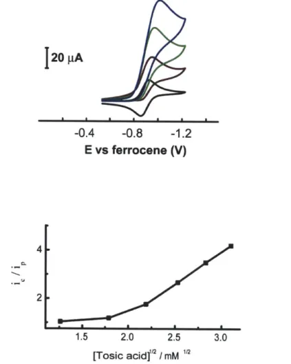
-0.4 -0.8 -1.2 E vs ferrocene (V) 4 2 1.5 2.0 2.5 3.0 [Tosic acid]"' / mMFigure 1.15. Cyclic voltammograms of 1 mM of 10 in 0.1 M NBu4PF6 acetonitrile solution at 0
(-), 4.8 (-), 8.0 (-), 12.0 (-) mM of tosic acid. (Top) The plot of ie/ip vs [tosic acid]"2. (Bottom) Scan rate: 100 mV/s. Glassy carbon working electrode (0.07 cm2) and Ag/AgNO
3
1.0
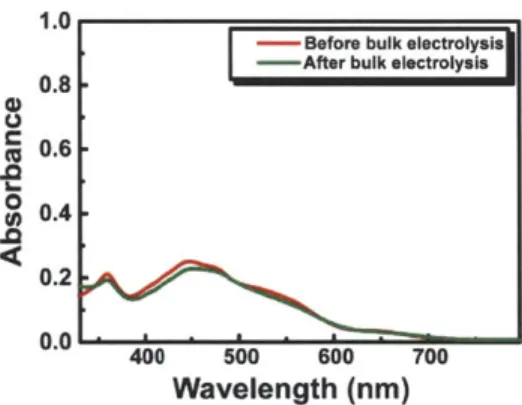
-Before bulk electrolysis -After bulk electrolysis
0.8 0.6
-e
U 0.4 0.2 0.0 400 500 600 700 Wavelength (nm)Figure 1.16. UV-vis spectra of the sample containing 10 obtained
before and after bulk electrolysis in the presence of tosic acid.
Complex 10, Co(bpda)(N03)2, exhibits a reversible wave for the Co" potential at -0.89 V vs the ferrocene/ferrocenium (Fc/Fc*) couple. In the presence of p-toluenesulfonic acid hydrate (tosic acid, pKa = 8.3 in acetonitrile),4' 10 produces catalytic cathodic waves near the
Co" redox couple (Figure 1.15). Overpotential for H2 production is -430 mV as thermodynamic potential for H2 production of 10 mM tosic acid in acetonitrile is -0.48 V.41 Control experiments performed in the absence of the complexes show that the working glassy carbon electrode is almost inert under the same experimental conditions. Bulk electrolysis was performed at ca. -1.2 V in a gas-tight electrochemical cell until 20 C of charges were consumed. The atmosphere in the headspace of the cell was analyzed with a GC to confirm H2 production. The current efficiency for H2 production of 10 was found to be -100%. By comparing UV-vis spectra of the solution containing the complexes before and after bulk electrolysis, the complexes appear to be quite stable during electrolysis (Figure 1.16).
In Figure 1.15, the plot of i/ip vs [tosic acid]12, where i4 is catalytic peak current and ip is peak current in the absence of acid, exhibits linear relationship at high acid concentration. Figure
1.17 shows that the catalytic current is almost linearly proportional to concentration of 10 and CV has plateau shape at 0.25 mM of 10 and 20 mM of tosic acid. Considering relationships
shown in Figure 1.15 and 1.17, the approximate rate constants for the overall H2 production reaction can be calculated from plateau current which is given by by i = nFACo*(D kf)1u2 (A = the
surface area of electrode, C,'* = the bulk concentration of catalyst, D = the diffusion coefficient,
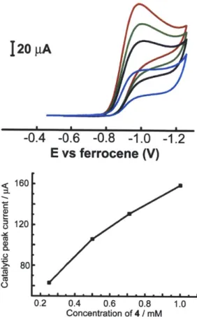
120
pA
-0.4 -0.6 -0.8 -1.0 -1.2
E vs ferrocene (V)
0.2 0.4 0.6 0.8 1.0
Concentration of 4 / mM
Figure 1.17. Cyclic voltammograms of 10 in 0.1 M NBu4PF6 and 20 mM tosic acid acetonitrile
solution at 0.25 (-), 0.5 (-), 0.71 (-), 1.0 (-) mM of 10. The plot of i, vs catalyst
concentrations. Scan rate: 100 mV/s. Glassy carbon working electrode and Ag/AgNO3 reference
electrode. 1.0 e 0.8 0.6 0.4-400 500 600 700 Wavelength (nm)
Figure 1.18. UV-vis spectra of ImM 10 in 0.1 M NBu4PF6 during bulk electrolysis. 0 (-), 25
(-), 50 (-), 75 (-), 100 s (-) from the initiation. Pt working and Ag/AgNO3 reference
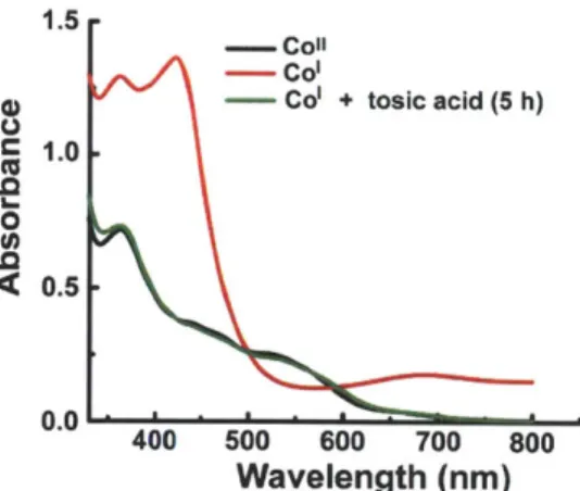
1.5 - Co
2+
- Cobpda
- Co(bpda + + tosic acid (2 h)
8 1.0 0 4 0.5
0.0 400 500 600 700 800 Wavelength (nm)
Figure 1.19. UV-vis spectra of Co'(bpda)*, Co"(bpda)2+ (10) and reaction mixture of Col(bpda)* and tosic acid.
Figure 1.18 is UV-vis spectrum changes of 10 during bulk electrolysis in the absence of acid and the spectra show the generation of a new species, Col. The same species can be produced chemically by the treatment with cobaltocene and the addition of tosic acid to Col results in the absorption features of Co". This suggests the electrocatalytic H2 production is mediated by Col.
As expected from the two added trifluoromethyl groups, complex 13 exhibits a Co"" redox couple at more positive reduction potential (-0.80 V) than 10. However, the complex does not produce pronounced catalytic waves upon addition of tosic acid. We believe that the tosic acid is not acidic enough to be reduced efficiently by Co, in 13. This is consistent with other
20 pA
-0.5 -1.0
E vs Fc/Fc(V)
Figure 1.20. Cyclic voltammograms of 1 mM of 13 in 0.1 M NBu4PF6 acetonitrile solution at 0
(-), 3.0 (-), 4.0 (-), 5.0 (-), 6.0 (-) mM of triflic acid. Scan rate: 100 mV/s. Glassy carbon working electrode (0.07 cm2) and Ag/AgNO
reports concerning structural perturbation of reduction potential; compounds with more positive reduction potentials owing to small structural changes are less nucleophilic and consequently less active for proton reduction.16,42 Pronounced catalytic waves can be observed when triflic acid (pKa = 2.6 in acetonitrile)41 is used as an acid source (Figure 1.20). The complex, however, was not stable enough in high acid concentration for bulk electrolysis.
Like 10, complex 14 also produces catalytic wave in the presence of tosic acid at almost the same potential as that for 10 (-0.90 V vs Fc/Fc*) (Figure 1.21) and chemically reduced
species results in Co" upon treatment with tosic acid (Figure 1.22). The complex generates hydrogen quanitatively and appears to be quite stable upon bulk electrolysis (Figure 1.23). However, it seems some impurities adsorbed onto the electrode contribute to the catalytic current
and complicate the electrochemistry. Washed electrode after electrochemical measurements produces catalytic wave (peak around -1.0 V) in acid solution without the complex, even though the washed electrode does not show electrochemical activity in the absence of acid. We speculate that the adsorbed species could be small amount of residual palladium species from coupling reaction for preparation of 7 which was not completely removed during the purification steps.
SEM images of glassy carbon plate used for bulkelectrolysis of 14 in the presence of tosic acid showed small particles on the surface and EDX analysis of the surface revealed that some parts of the surface contained palladium (Figure 1.24). This indicates study of catalyst prepared through metal catalyzed reaction should be carried out with extreme care. The hangman complex
14 itself does not show any enhancement from structural modification and this is possibly
20pA
0.0 -0.5 -1.0 -1.5 E vs Fcd/Fc(V)
Figure 1.21. Cyclic voltammograms of 1 mM of 14 in 0.1 M NBu4PF6 acetonitrile solution at 0
(-), 2.0 (-), 3.2 (-), 6.4 (-), 9.6 (-) mM of tosic acid. Scan rate: 100 mV/s. Glassy carbon
1.5
- Coll
- Co'
-Col + tosic acid (5 h)
1.0 .0 < 0.5 0.0 L- '- - - -400 500 600 700 800 Wavelength (nm)
Figure 1.22. UV-vis spectra of Hangman Col, Hangman Co" (14) and
reaction mixture of Co, and tosic acid.
1.0
Before bulk electrolysis
--- After bulk electrolysis
0.8 0 D 0.4 .0 0.2 0.0 400 500 600 700 Wavelength (nm)
Figure 1.23. UV-vis spectra of the sample containing 14 obtained
before and after bulk electrolysis in the presence of tosic acid.
because the Co"" couple is at too positive potential to reduce the hanging carboxylic acid group. The thermodynamic reduction potential of 1mM benzoic acid is -1.20 V in acetonitrile41 and we found that chemically reduced species of 14 did not react with benzoic acid.
In conclusion, we have prepared derivatives of diacetylpyridine, 7-9 through Suzuki coupling reaction following borylation of 4-position of diacetylpyridine. These derivatives were used as a precursor to derivatized macrocyclic complexes, 11-15, by metal mediated template synthesis. Complex 11 and 14 have a hanging carboxylic group over the metal center. Complex 12 and 15 have cofacial bimetallic structure. We showed the macrocyclic complex 10 is a stable catalyst for electrochemical hydrogen production. The electron withdrawing groups on 13 shifts reduction potential of the complex toward positive. However, the complex shows less activity in hydrogen generation.
Figure 1.24. SEM and EDX analyses of glassy carbon plate after bulkelectrolysis of 14 in the
1.4
Experimental Section
1.4.1
Hydrogen Generation by Hangman Metalloporphyrins
'H NMR spectra (500 MHz) were recorded on samples in CDCl3 at room temperature
unless noted otherwise. Silica gel (60 4m average particle size) was used for column chromatography. 4-Formyl-5-bromo-2,7-di-tert-butyl-9,9-dimethylxanthene (3)39
5-pentafluorophenyldipyrromethane (4),40
1,9-bis(pentafluorobenzoyl)-5-(pentafluorophenyl)dipyrromethane (5),36
1,9-bis(pentafluorobenzoyl)-5-(pentafluorophenyl)dipyrromethane dicarbinol (5-OH),36
5-(4-(5-hydroxycarbonyl-2,7-di-tert-butyl-9,9-dimethyl-xanthene))-10,1 5,20-tris(pentafluorophenyl)-porphyrinatocobalt(II) (1-Co) 3 6
were prepared as described in the literature. THF (anhydrous), methanol (anhydrous) and CH2Cl2
(anhydrous) and all other chemicals were reagent grade and were used as received. LD-MS data was measured on porphyrins in the absence of matrix.
The microwave-assisted reactions were performed inside the cavity of a CEM Discover microwave synthesis system equipped with infrared, pressure and temperature sensors for monitoring the synthesis. The reaction vessels were 10 mL crimp-sealed thick-wall glass tubes. The contents of each vessel were stirred with a magnetic stirrer.
UV-vis spectra were recorded at room temperature in quartz cuvettes in anhydrous
CH2C12 on a Varian Cary 5000 UV-vis-NIR spectrophotometer. Steady state emission spectra
were recorded on an automated Photon Technology International (PTI) QM 4 fluorimeter equipped with a 150-W Xe arc lamp and a Hamamatsu R928 photomultiplier tube. Excitation light was wavelength selected with glass filters. Solution samples were prepared under ambient atmosphere in anhydrous CH2Cl2 and contained in screw-cap quartz fluorescence cells.
Syntheses
5-(4-(5-bromo-2,7-di-tert-butyl-9,9-dimethylxanthene))dipyrromethane (6).
A mixture of 4-formyl-5-bromo-2,7-di-tert-butyl-9,9-dimethylxanthene 3, (1.00 g, 2.33
mmol) and pyrrole (15.6 mL, 233 mmol) in a 50-mL flask was degassed with a stream of argon for 10 min at room temperature. The mixture was heated to 75 'C to obtain a clear solution. InCl3 (50.0 mg, 0.226 mmol) was then added, and the mixture was stirred at 75 'C for 2 h. A