• Aucun résultat trouvé

Comparing phonon dephasing lifetimes in diamond using Transient Coherent Ultrafast Phonon Spectroscopy

N/A
N/A
Protected

Academic year: 2021

Partager "Comparing phonon dephasing lifetimes in diamond using Transient Coherent Ultrafast Phonon Spectroscopy"

Copied!
8
0
0

Texte intégral

(1)

Publisher’s version / Version de l'éditeur:

Diamond and Related Materials, 19, 10, pp. 1289-1295, 2010-06-11

READ THESE TERMS AND CONDITIONS CAREFULLY BEFORE USING THIS WEBSITE. https://nrc-publications.canada.ca/eng/copyright

Vous avez des questions? Nous pouvons vous aider. Pour communiquer directement avec un auteur, consultez la première page de la revue dans laquelle son article a été publié afin de trouver ses coordonnées. Si vous n’arrivez pas à les repérer, communiquez avec nous à PublicationsArchive-ArchivesPublications@nrc-cnrc.gc.ca.

Questions? Contact the NRC Publications Archive team at

PublicationsArchive-ArchivesPublications@nrc-cnrc.gc.ca. If you wish to email the authors directly, please see the first page of the publication for their contact information.

NRC Publications Archive

Archives des publications du CNRC

This publication could be one of several versions: author’s original, accepted manuscript or the publisher’s version. / La version de cette publication peut être l’une des suivantes : la version prépublication de l’auteur, la version acceptée du manuscrit ou la version de l’éditeur.

For the publisher’s version, please access the DOI link below./ Pour consulter la version de l’éditeur, utilisez le lien DOI ci-dessous.

https://doi.org/10.1016/j.diamond.2010.06.002

Access and use of this website and the material on it are subject to the Terms and Conditions set forth at

Comparing phonon dephasing lifetimes in diamond using Transient

Coherent Ultrafast Phonon Spectroscopy

Lee, K.C.; Sussman, B.J.; Nunn, J.; Lorenz, V.O.; Reim, K.; Jaksch, D.;

Walmsley, I.A.; Spizzirri, P.; Prawer, S

https://publications-cnrc.canada.ca/fra/droits

L’accès à ce site Web et l’utilisation de son contenu sont assujettis aux conditions présentées dans le site LISEZ CES CONDITIONS ATTENTIVEMENT AVANT D’UTILISER CE SITE WEB.

NRC Publications Record / Notice d'Archives des publications de CNRC:

https://nrc-publications.canada.ca/eng/view/object/?id=75d8522b-e408-4a05-8151-7f4115690d13

https://publications-cnrc.canada.ca/fra/voir/objet/?id=75d8522b-e408-4a05-8151-7f4115690d13

(2)

Comparing phonon dephasing lifetimes in diamond using Transient Coherent

Ultrafast Phonon Spectroscopy

K.C. Lee

a

, Benjamin J. Sussman

a,c,

, J. Nunn

a

, V.O. Lorenz

a

, K. Reim

a

, D. Jaksch

a

, I.A. Walmsley

a

,

P. Spizzirri

b

, S. Prawer

b

aClarendon Laboratory, University of Oxford, Parks Road, Oxford, OX1 3PU, UK

bCenter for Quantum Computer Technology, School of Physics, The University of Melbourne, Parkville, Victoria 3010, Australia cNational Research Council of Canada, Ottawa, Ontario, K1A 0R6, Canada

a b s t r a c t

a r t i c l e

i n f o

Article history: Received 15 June 2009

Received in revised form 27 April 2010 Accepted 1 June 2010

Available online 11 June 2010 Keywords:

Raman spectroscopy Phonon lifetime Decoherence

Transient Coherent Ultrafast Phonon Spectroscopy (TCUPS) is utilized to study phonon dephasing lifetimes in various diamond types. Samples of natural, chemical vapour deposited, and high pressure high temperature diamond are compared showing significant differences. Dephasing mechanisms are discussed. © 2010 Elsevier B.V. All rights reserved.

1. Introduction

The extraordinary physical properties of diamond and diamond-like materials continue to be an area of extensive research[1–4]. Recent advancements in synthetic fabrication techniques have resulted in increased industrial and scientific application[5–7]. A central source of diamond's uncommon electronic and thermal properties is its unique lattice and corresponding phonon features. Recently, a new spectral technique has been developed to characterize phonon decay: Transient Coherent Ultrafast Phonon Spectroscopy (TCUPS) [4]. TCUPS is a convenient, spectral method for measuring phonon dephasing. Here, TCUPS is used to compare the phonon lifetime of natural, chemical vapour deposited (CVD), and high pressure high temperature (HPHT) diamond. The measurements are highly precise and repeatable, showing a significant variation between the CVD sample and the others. Traditionally, the phonon lifetime has been indirectly measured via the inverse of the first order Raman linewidth[8]. More recently, time-domain techniques have been developed that directly probe the time evolution of sample reflectivity or transmissivity, following impulsive phonon excitation with few-femtosecond laser pulses[9]

and can achieve high relative resolution[10]. While Raman spectros-copy employs steady-state fields and impulsive scattering utilizes short pulse durations comparable to vibrational times, TCUPS makes use of the intermediate, or transient regime[11]. Use of the transient

regime reduces some experimental challenges of impulsive studies, since readily available Ti:sapphire oscillators (of duration∼80 fs) can be used. TCUPS is also applicable in the weakly pumped spontaneous limit, and thus avoids heating and the excitation of the large phonon populations that can alter the apparent decay rate in stimulated Raman experiments[12].

TCUPS can be understood from the perspective of Young's two-slits experiment. In TCUPS two coherent, time delayed femtosecond pump pulses Raman scatter from the diamond lattice and the Stokes light is detected by an imaging spectrometer. At low power, when the process is strictly spontaneous, on average less than one Stokes photon is produced per pump pulse pair. The production of a Stokes photon from the first pump corresponds to one slit/pathway and the production of a Stokes photon from the second corresponds to another. The combined Stokes light is detected on an imaging spectrometer with a slow detector, measuring the sum of the amplitudes from the two paths, resulting in spectral (Ramsey) fringes, provided that the two pathways are phase coherent. At short times, the two pathways are strongly phase correlated. However, as the time-delay between the two pulses is increased, decoherence occurs as vibrational information leaks into the environment and the ‘which-way’ information becomes available. The corresponding reduction in fringe visibility can then be used as a measure of decoherence. 2. Experiment

In the experiment (Fig. 1), a pair of coherent pump pulses temporally separated by a few picoseconds are incident upon the

⁎ Corresponding author.

E-mail address:ben.sussman@nrc.ca(B.J. Sussman).

0925-9635/$ – see front matter © 2010 Elsevier B.V. All rights reserved. doi:10.1016/j.diamond.2010.06.002

Contents lists available atScienceDirect

Diamond & Related Materials

(3)

diamond. The first pump pulse spontaneously Raman scatters off the diamond to create a Stokes photon and an optical phonon. Stokes generation from the second pulse is also spontaneously initiated by the same vacuum fluctuation and both Stokes pulses are incident upon a slow detector. The two Stokes pulses are phase coherent with each other provided that they are initiated within the coherence time of the phonon, in which case they can interfere in a spectrometer to produce spectral fringes. As the pulse separation is increased, the visibility of the fringes decreases, thus permitting a measurement of the phonon dephasing time.

The pump, generated by a mode locked Ti:sapphire laser (Coherent Mira) of 80 fs duration, centered at 808 nm, is propagated through a Mach–Zehnder interferometer to produce the time delay. Spectral fringes in the pump or Stokes pairs are measured and given as a function of carrier wavelength λ0and time delay T, by Δλ=λ02/(cT).

Care is taken to minimize phase fluctuations through the interferom-eter and in our case, no measurable phase drift is observed in our pump spectral fringes over the time scales of our measurements.

The pump pulses are then focused with a 50 mm AR coated lens down to an area∼600 μm2through up to 0.5 mm of diamond (i.e.,

Fresnel number∼0.1). A 30 cm spectrometer coupled to a CCD camera is used to observe the spectral fringes of the Stokes light. The spectral fringe visibility is then measured as a function of the delay on the interferometer, which is tuned from 2 to 11.5 ps.

To obtain the coherence lifetime of the phonons in the diamond, we record the decay in spectral fringe visibility of the Stokes light with increasing temporal delay. Factors such as mechanical imprecision in the translation stage used in the interferometer and finite pixel widths of the CCD camera are also sources of fringe visibility reduction. The fringes are well sampled by the CCD at all delays. Other errors are mitigated by normalising the visibility of the Stokes light fringe visibility against that of the pump.

Diamond is a face-centered cubic lattice, with two carbon atoms per unit cell. The space group is Fd3m (Oh7) and the crystal group is m3m

(Oh). There is a triply degenerate optical phonon mode with

vibrational symmetry T2g (Γ5+). The first order Raman shift is

1332 cm− 1. The samples were all polished with faces on 〈100〉. This

is a convenient reference orientation that samples one phonon mode

such that polarization selection rules produce output Stokes light orthogonally polarized to the input[13].

The Stokes-to-pump-photon ratio is of order 10− 12. A cooled CCD

camera was used (iXon DU-897). To reduce noise from the laser oscillator, bandpass filters are utilised to eliminate high order spectral frequencies (Fig. 2). Visibility measurements at each time delay are taken over a period of 100 s.

Fig. 1. Experimental setup. An oscillator pulse is split into two time delayed pulses and focused through the diamond sample. A bandpass filter removes background oscillator modes before the diamond and a longpass filter rejects the pump and transmits the Stokes before the spectrometer.

Fig. 2. Raman scattering transition in diamond. Ground state phonons are excited with the incident 808 nm pump, via a Raman transition, to the optical phonon mode, emitting a 906 nm Stokes pulse.

Fig. 3. Polarization microscopy images of the diamond: a) CVD; b) natural IIa; and c) HPHT. See text for discussion.

(4)

3. Results

Three different types of diamonds were investigated. The first was a single crystal diamond plate (3 × 3 × 0.5 mm) synthesized by Chemical Vapour Deposition (CVD). The manufacturer (Element 6) specifications are that the impurity level is b1 ppm N and b0.05 ppm B with a low dislocation density at b104cm− 2(Fig. 3a). Whilst the

cross polarized image reveals irregular birefringence patterns caused by local stress and strain, there are no significant straight line features associated with dislocations. The second sample was a natural type IIa slab of dimensions 3 ×3 ×0.25 mm. Such samples, whilst typically pure, with a N and B concentration of less than 1 ppm, have a high dislocation density of order∼108−109cm− 2[14]. Indeed imaging

under crossed polarizers (Fig. 3b) reveals a dense network of dislocations, which appear as alternating dark and bright stripes. The last sample studied was a high pressure, high temperature diamond (3.2×3.2 ×0.42 mm), yellow in colour, with a N concentra-tion of between 10 and 100 ppm (Fig. 3c). This sample showed similar dislocation density to the CVD, if not lower. The yellow and black parts inFig. 3c represent different growth sectors of the diamond where the crystal lattice orientations are different from each other. Ultraviolet photoluminescence images of the diamond samples have shown that both the nitrogen impurities and dislocations are uniformly distrib-uted in the 3 samples.

Fig. 4shows the Stokes fringe visibility as a function of pump delay time (given on the left of each column). As expected, the spectral fringes in the Stokes spectrum are observed with fringe visibility decaying exponentially with pump delay. A least squares fit to the function A0+A1cos[A2ω + A3] (where Ai′s are the fitted numbers and

ω is the frequency) was applied to the data and the extracted fringe visibility, defined as A1/A0, is plotted as a function of delay time in

Fig. 5for each of the 3 various diamonds in one run of the experiment.

From the data in Fig. 5 the phonon decoherence time may be deduced for each sample. The lifetimes are summarized inTable 1, which also shows the corresponding (FWHM) linewidths. It should be noted that each piece of diamond was measured five times, non-sequentially, and the combined lifetime values have an error of less than 0.2 ps. In order to achieve such repeatability, care has to be taken to ensure that the focusing lens following the diamond is well positioned to collect the Stokes light and that it is brought sharply into focus as it enters the spectrometer.

The TCUPS measurements were compared with the conventional Raman spectra from a Renishaw spectrometer using a 532 nm source.

Fig. 4. Stokes spectral fringe visibility as a function of pump delay (on the left of each column). For clarity, we have plotted half of the data generated from one run of TCUPS measurement, and we have used different “Counts” scales for the left (2 to 6 ps) and right (7.4 to 11.4 ps) columns. The spectral fringes in the Stokes spectrum are observed with fringe visibility decaying exponentially with pump delay. The blue dots represent actual data and the red lines are the least square best fit lines used to calculate the visibility of the spectral fringes.

Fig. 5. A plot of spectral fringe visibility versus path delay set by the interferometer. These are typical runs obtained from the 3 diamonds.

(5)

The first order Raman spectra are shown inFig. 6. While accuracy of the Raman spectra are not sufficient to directly compare with the TCUPS measurement, they are sufficiently precise to distinguish the difference between samples. Here, Lorentzian linewidths were assumed, although in general diamonds can display varied shapes that would manifest themselves as non-exponential behavour in the TCUPS traces[15,16]. As expected, the CVD sample has a narrower linewidth than the other two samples, at 2.1 cm− 1and 2.4 cm− 1

(± 0.1 cm− 1) respectively. Both TCUPS and the Raman spectroscopic

measurements showed identical differences in phonon linewidths within the accuracy of both techniques.

4. Theory

The first control pulse is inelastically scattered from the optical phonon of the diamond, creating Stokes light. The second pulse then inelastically scatters off the diamond to create a second Stokes pulse; at short time delays there exists a definite phase relation between the two Stokes pulses which is limited by the phonon decoherence time. The main source of decoherence in this picture is the anharmonic decay of the optical phonon[17].

Due to collective enhancement arising from the coherence and geometry of the excitation pulse, Stokes light is principally scattered from one phonon mode into one optical mode in the forward direction

[18]. Consequently, the dynamics can be understood in terms of a single phonon mode operator B̂ and a single optical mode operator Â, as shown below.

4.1. Effective Hamiltonian

In complete analyses of the Raman interaction[19–22], propaga-tion effects of the Stokes light are taken into account by using

Maxwell's wave equation, where the excitation of the medium acts as a source term. Both the Stokes light and excitation in the medium are decomposed into longitudinal and transverse modes. The analysis here can be simplified for two reasons, which allow us to restrict our considerations to one longitudinal and transverse mode. We limit ourselves to one longitudinal mode since our Raman scattering is in the linear regime (in the experiment, the probability of Stokes generation is ∼0.01 per pulse). Consequently every atom in the medium interacts with the input field in the same way and we therefore ignore the propagation effects[18]which are responsible for the various longitudinal modes. Furthermore, we ignore all higher transverse modes as the Fresnel number for our interaction is smaller than 1[20].

Within the rotating wave approximation, the Raman Hamiltonian is given by

ˆ

Hðt′Þ = ℏκEPðt′Þ ˆE†Sðt′Þ ˆB†ðt′Þ + H:c: ð1Þ

where t′ is the co-moving time t′ =t−z/c, z is the distance along the direction of pump, EP(t′) is the classical pump, and ˆE†Sðt′Þ is the Stokes

mode operator. The phonon creation operator is given by ˆB†

ðt′

Þ and κ represents the coupling responsible for the Stokes creation, which is the product of various matrix elements associated with the different exciton-phonon interactions in Stokes generation[13].

To understand the spectral characteristics of the generated Stokes light, we re-write Eq. (1) in terms of ˜EPðωÞ; ˜E†SðωÞ; ˆ˜B

ðωÞ, the Fourier transformed quantities of EPðt′Þ; E†Sðt′Þ; ˆB

ðt′

Þ respectively assuming the phonon to be sharply peaked at ωph ˆB†ðt′Þ = ˆ˜B†ðωphÞ expf−iωpht′g

h i

ˆ

H t′ð Þ ≃ ℏκ∫∫˜EPðωÞ ˆ˜E

Sðω′Þ ˆB†eiðω−ω′−ωphÞt′dωdω′ + H:c: ð2Þ

For brevity we now take ˆB†

to mean ˆ˜B†ðωphÞ. This is followed by an

integration over z to give an effective Hamiltonian treating the whole ensemble as a single system

ˆ

Heff= ℏg ˆA†ˆB+ H:c:

ð3Þ where  =∫Ω(ω)â(ω)dω is the superposition annihilation operator for Stokes light [â(ω) is the individual Stokes mode annihilation operator], ΩðωÞ = ˜EPðωÞ =

ffiffiffiffiffiffiffiffiffiffiffiffiffiffiffiffiffiffiffiffiffiffiffiffiffiffiffiffiffiffiffiffi ∫j ˜EPðω′Þj2dω′

q

is the normalised pulse envelope, the effective coupling in the frequency domain is[22,23]

g = κ ffiffiffiffiffiffiffiffiffiffiffiffiffiffiffiffiffiffiffiffiffiffiffiffiffiffiffiffiffi∫jEPðωÞj2dω

q

: ð4Þ

Here, κ∝Δ− 2[13], where Δ is the detuning of the pump away

from the intermediate exciton state which is at 5.2 eV above the ground state [24]. Since the detuning Δ is much larger than the bandwidth of the pump pulse, we take g to be constant.

Starting from Eq. (3), we provide both the Heisenberg and Schrödinger pictures to explain the presence of spectral fringes in the Stokes spectrum and the decay of these fringes.

4.2. Heisenberg picture 4.2.1. Stokes generation

The sequence of Stokes generation and phonon decay is analysed in a piecewise manner (Fig. 7). By ignoring dephasing effects during the short duration of the pump, the equation of motion of the operators obtained from Eq. (3) are

˙ˆAðtÞ = ig ˆB†

ðtÞ ð5Þ

˙ˆBðtÞ = ig ˆA†

ðtÞ: ð6Þ

Table 1

Diamond decoherence times and linewidths, as measured by TCUPS. The errors correspond to the standard deviation of the lifetimes from 5 separate measurements on each diamond.

Diamond TCUPS

Type Lifetime Error Linewidth Error

ps ps cm− 1 cm− 1

CVD 7.0 ±0.2 1.5 ±0.07

IIa 5.7 ±0.2 1.9 ±0.07

HPHT 5.7 ±0.2 1.9 ±0.07

Fig. 6. The first order Raman spectra of the diamond samples. The CVD sample showed an intensity offset due to the presence of a broadband background fluorescence.

(6)

We find that after time t=τ, the pump duration, the solutions are given by

ˆA†

ðτÞ = coshðgτÞ ˆA†0−i sinhðgτÞ ˆB0 ð7Þ

ˆBðτÞ = i sinhðgτÞ ˆA†

0+ coshðgτÞ ˆB0: ð8Þ

Â0,B̂0are the annihilation operators for Stokes photon and phonon

respectively at t = 0. We can obtain the Stokes spectrum by calculating the expectation value of the operator ˆa†

ðω; τÞ ˆaðω; τÞ. We note that the Heisenberg equation of motion for the Stokes photon annihilation operator can also be obtained from Eq. (3)

˙ˆaðω; tÞ = igΩ ðωÞˆB†

ðtÞ ð9Þ

ˆaðω; τÞ = iΩ ðωÞf−i coshðgτÞ−1½ Š ˆA0+ sinhðgτÞ ˆB†0g: ð10Þ

The solution given in Eq. (10) requires the solution given in Eq. (8). Thus the Stokes spectrum is

IðωÞ = 〈 ˆa†

ðω; τÞ ˆaðω; τÞ〉 ð11Þ = jΩðωÞj2sinh2ðgτÞ〈 ˆB0ðωÞ ˆB

0ðωÞ〉 ð12Þ

= jΩðωÞj2sinh2ðgτÞ; ð13Þ assuming there is negligible phonon population in the thermal state. For small coupling gτ the spectral shape of I(ω) is proportional to the spectrum of the pump light |EP(ω)|2.

4.2.2. Phonon decay

In between the two pump pulses, the effects of phonon dephasing are included by adding a phenomenological decay term:

˙ˆBðtÞ = −ΓˆBðtÞ: ð14Þ A full quantum treatment would include a Langevin operator in Eq. (14) to maintain commutator relations for B̂ such that 〈½ ˆBiðtÞ; ˆB†iðtފ〉 = 1

for all times. Alternatively we may use the normally ordered operator when calculating expectation values for the same effect[4,23].

The solution after time t =T, the delay between the two pump pulses, is given by

ˆBðT + τÞ = ˆBðτÞe−ΓT: ð15Þ 4.2.3. Pulse sequence

For the last part of the pulse sequence, the Stokes generation is once again governed by Eq. (7) and (8). Since the pump pulses are temporally separated, we assume that the second Stokes generation is initialized by B̂(T +τ) in Eq. (15) only.

To differentiate between Stokes and phonon modes involved in the first and second pulses, we use subscripts i a {1, 2}, thus, Â1(t),B̂2(t)

denote the Stokes operator during the first pulse and phonon operator during the second pulse respectively. From the above arguments, we can also write the initial phonon operator of the second pulse as B̂0,2=B̂(T+τ)=B̂1(τ)e− ΓT. Using this notation, the signal detected by

the spectrometer is represented by the operator

ˆaDðωÞ = 1ffiffiffi 2

p ˆa1ðω; τÞ + ˆa2ðω; τÞeiωT

h i

: ð16Þ

In terms of the initial operators, the Stokes spectrum is given by IðωÞ = 〈 ˆa† DðωÞ ˆaDðωÞ〉 = jΩðωÞj2ðgτÞ2〈ˆB0;1ˆB†0;1〉 ð17Þ + jΩðωÞj2 ðgτÞ2e−ΓTcos ωTð Þ〈 ˆB0;1ˆB†0;1〉+ O ðgτÞ4 h i : ð18Þ

Motivated by the fact that we are in the weak coupling spontaneous regime, we only keep terms that are up to second order in the effective coupling (gτ). The first term represents spontaneously scattered Stokes light from both pulses. Spectral fringes are generated by the second term, which decays. The exponential factor represents the decay of coherence, which is measured in this experiment. Assuming negligible thermal phonon population, we calculate the expectation values of the operators to give

IðωÞ≃jΩðωÞj2ðgτÞ21 + e−ΓTcosωT: ð19Þ

Even though there is no stimulation at the lowest order, the Stokes pulses are coherent within the lifetime of the phonon.

Standard diamond lifetime measurements in the literature

[12,25,26] involve the direct measurement of phonon lifetime, which in the operator language is given by

〈ˆB†ðTÞ ˆBðTÞ〉∝e−2ΓT〈ˆB†ð0Þ ˆBð0Þ〉: ð20Þ The Raman linewidth in frequency space is given by Γ=2/T2where

T2is the coherence lifetime[27]. In cm−1, the linewidth is δν=(πcT2)−1.

It has been shown (see[28,29]and references therein) that the anharmonic phonon self energy, the term in the Hamiltonian describing phonon–phonon interactions that is the main cause of phonon decay, is a frequency dependent term. This implies that the spectral fringe visibility would not decay precisely exponentially with pump pulse separation. However, we note that in the single phonon regime and at room temperature, our experimental data fit the predicted exponential decay curve (Fig. 5) well.

4.3. Schrödinger picture

In the Heisenberg picture, we have derived the evolution of the joint photon-ensemble system by calculating the time evolution of the operators and deriving the expectation values. It is worthwhile to contrast the solutions with those obtained from the Shrödinger picture. For the short pulses, the unitary operator Û corresponding to evolution of initial (vacuum) state by the Hamiltonian [Eq. (3)] can be perturbatively expanded up to first order,

ˆUðτÞ = e−iHˆ ℏτ ð21Þf〉≃ 1−i1 ℏHτˆ   j0〉 ð22Þ

Fig. 7. Evolution of the phonon. (a) Phonon is spontaneously created by a pump pulse and evolves as Eqs. (7) and (8). (b) The phonon decays for time T via (14). (c) A second pump pulse scatters off B̂(T +τ).

(7)

where the initial vacuum state |0〉 is connected to the final state |ψf〉

via the Raman interaction. The higher order terms, including the stimulated emission, are not included.

Denoting operators associated with the first and second pulse with the subscripts 1, 2 respectively, the two pulse interaction is written as

jψf〉= ˆU2ðτÞ ˆU1ðτÞj0〉 ð23Þ ≃ 1−igτ ˆA† 2ˆB†2+ ˆA†1ˆB†1   h i j0〉: ð24Þ

As in the Heisenberg treatment, we obtain the Stokes spectrum by taking the expectation value of the operator ˆa†

DðωÞ ˆaDðωÞ in Eq. (16),

this time, with state |ψfN. The detected signal is

IðωÞ = 〈ψfj

1 2 ðˆa

1ˆa1+ ˆa†2ˆa2Þ + Rf ˆa†1ˆa2eiωTgjψf〉 ð25Þ

= ðgτÞ2 jΩðωÞj2 〈0j1 2 ðˆB1ˆB†1+ ˆB2ˆB†2Þj0〉 + cosðωTÞ〈0j ˆB1ˆB†2j0〉   : ð26Þ As before, we take the normally ordered operators and use the same arguments as inSection 4.2.2to relate B̂1and B̂2, we find that

I(ω) becomes Eq. (19).

The utility of the Schrödinger picture is that it emphasizes the analogy with Young's two-slit experiment. After the full TCUPS interaction, the joint photon-ensemble state |ψfN is given by Eq. (24), where the subscripts denote the two pathways for Stokes photon generation. We see that |ψfN contains a coherent superposition of the two pathways and spectral fringes in the Stokes spectrum appear after the two pathways are allowed to interfere in a slow detector. It is also useful to note that the Raman Hamiltonian is of the same form as that of parametric down conversion[30]. In this sense, the generated state is a two-mode squeezed state which can be used to entangle the optical phonon and the Stokes photon.

5. Experimental conditions

TCUPS is a robust tool for investigating material properties at the picosecond time scale, and allows a high degree of freedom in the choice of experimental parameters. The theoretical analysis above assumed three main conditions: spontaneous Stokes generation, pump pulse duration within the transient regime for the medium excitation, and single mode interactions.

In order to avoid any stimulated scattering, the effective Raman coupling strength g should be kept low. The measured rate of Stokes photon generation in our experiment corresponds to gτ∼10− 2. A low

coupling strength could be achieved providing the peak field strength of the pump pulse is not too strong and the Raman detuning from the exciton state, Δ, is large (seeFig. 1). For diamond, the conduction band is 5.5 eV above the ground state, which corresponds to 225 nm[31]. This is energetically well above the pump pulse photons in our experiment. The presented data was pumped at 808 nm, but TCUPS measurements have been performed at wavelengths in the range of 780 nm–830 nm. Competition from fluorescence becomes a problem at shorter wavelengths, particularly for HPHT.

As well as keeping the parameter gτ small, a short pulse serves to keep the Raman interaction within the transient regime. The coupled Eqs. (5) and (6) model the Raman interaction in the absence of any dephasing effects. In our case, the phonon coherence lifetime can be as short as 5 ps, which implies that good sampling limits pump pulse durations to less than roughly 500 fs.

For accurate results, both pump pulses must address the same single excitation mode in the diamond. By maintaining the Fresnel number of the confocal setup at b1, only one transverse mode is

excited in the diamond. This therefore sets an upper limit to the spot size that could be sampled in the diamond. In our measurements, the focused spot size was arbitrarily chosen to be 600 μm2and we have

found that T2lifetimes measured on different spots on the diamond

are identical withinthe accuracy of TCUPS. We anticipate, however, that measurements made with a more tightly focused spot size and sampling volume may be more sensitive to local variations in the diamond samples. Thus, if the sample contains uneven concentration of dislocations and impurities, then T2 measurements would be

location specific. 6. Discussion

The anharmonic decay time of diamond at zero temperature and pressure has been calculated as 10.5 ps (1.01 cm− 1) [32]. This

calculated lifetime is based upon the spontaneous decay of an optical phonon into two acoustic phonons. The observed widths of the literature, however, vary considerably from 1.2 cm− 1to 4.75 cm− 1

[8,9,12,25,26]. The large variance is due to a number of factors including: spectrometer limitations, source linewidths, isotopic mass defects, nitrogen impurities, cyrstal boundaries, and stress gradients

[3].

Here, TCUPS has been used to differentiate the optical phonon lifetimes of CVD, HPHT and natural (IIa) diamonds. The results in

Table 1reveal a somewhat unexpected difference between the three types of diamond samples that would normally be difficult to observe using more standard Raman scattering techniques. The CVD sample consistently shows a longer lifetime than either the natural or HPHT samples. Two obvious sources of phonon scattering in diamonds are impurities (most notably N) and dislocations. Despite the fact that the type IIa sample is clear and contains a low level of N, whereas the HPHT sample is yellow containing up to 100 ppm of N, there appears to be very little difference in the phonon lifetime. On the other hand, the CVD sample, with an N concentration of the same order of magnitude as the IIa sample, shows a lifetime approximately 20% longer. The dislocation density is much higher in the IIa sample than the single crystal CVD. A tentative conclusion might therefore be that reducing the dislocation density results in an increase in the lifetime and might be a more important factor in phonon scattering than the N impurities.

It is noteworthy that the present technique is sufficiently sensitive to reveal such differences. Measurement of the absolute peak width in Raman scattering is often subject to much higher errors than the 0.07 cm−1achieved here. It is also noteworthy that the present technique

samples a comparatively large volume of the sample (∼10−4mm3) as

compared to micro-Raman sampling whilst avoiding issues resulting from the presence of hot phonons.

While the decoherence time of diamond is long for phonon modes in solids, it is short in comparison to many other molecular, atomic, and nuclear degrees of freedom. Nevertheless, diamond's large Raman shift allows for easy spectral filtering and the convenience of working with a room temperature solid. As noted, the Raman interaction Hamiltonian can be used to create a two-mode squeezed state between the optical phonon and the Stokes photon. In TCUPS this phonon coherence was created and measured using femtosecond pulses. Whilst the absolute lifetime of the phonon is short, it is still 2 orders of magnitude longer than the interaction time needed to create the excitation, and one can also in principle perform many coherent operations within the phonon lifetime. Thus there is the interesting possibility that diamonds and their phonon modes might be useful for implementations of quantum information protocols.

Acknowledgment

This work was supported by the EPSRC through the QIP IRC (GR/ S82716/01) and project EP/C51933/01. JN thanks Hewlett-Packard. IAW was supported in part by the European Commission under the

(8)

Integrated Project Qubit Applications (QAP) funded by the IST directorate as Contract Number 015848, and the Royal Society. BJS was supported in part by the Natural Sciences and Engineering Research Council of Canada and the Royal Society.

The authors are particularly grateful to Dr. Daniel Twitchen (Element 6 Ltd.) for optical characterization and expertise in the material properties of diamond.

References

[1] G. Balasubramanian, et al., Nat. Mater. 8 (2009) 383. [2] P. Neumann, et al., Science 320 (2008) 1326.

[3] A. Neves, Properties, Growth and Applications of Diamond, Institution of Electrical Engineers, London, 2001.

[4] F.C. Waldermann, et al., Phys. Rev. B: Condens. Matter Mater. Phys. 78 (2008) 155201.

[5] S. Prawer, A.D. Greentree, Science 320 (2008) 1601. [6] J.R. Maze, et al., Nature 455 (2008) 644.

[7] J. Ristein, W. Zhang, L. Ley, Phys. Rev. E Stat. Nonlinear Soft Matter Phys. 78 (2008) 041602.

[8] S.A. Solin, A.K. Ramdas, Phys. Rev. B: Condens. Matter Mater. Phys. 1 (1970) 1687. [9] T.K. Cheng, et al., App. Phys. Lett. 57 (1990) 1004.

[10] C. Aku-Leh, et al., Phys. Rev. B: Condens. Matter Mater. Phys. 71 (2005) 205211.

[11] N. Bloembergen, et al., Indian J. Pure Appl. Phys. 9 (1971) 874. [12] A. Laubereau, D. von der Linde, W. Kaiser, Phys. Rev. Lett. 27 (1971) 802. [13] W. Hayes, R. Loudon, Scattering of Light by Crystals, Dover Publications, New York,

2004.

[14] M. Gaukroger, et al., Diamond Relat. Mater. 17 (2008) 262. [15] L. Bergman, R.J. Nemanich, J. Appl. Phys. 78 (1995) 6709.

[16] W.J. Borer, S.S. Mitra, K.V. Namjoshi, Solid State Commun. 9 (1971) 1377. [17] P.G. Klemens, Phys. Rev. 148 (1966) 845.

[18] L.M. Duan, J.I. Cirac, P. Zoller, Phys. Rev. A 66 (2002) 023818. [19] W. Wasilewski, M.G. Raymer, Phys. Rev. A 73 (2006) 063816. [20] K. Hammerer, A.S. Sorensen, E.S. Polzik, Rev. Mod. Phys. 82 (2010) 1041. [21] A.V. Gorshkov, et al., Phys. Rev. A 76 (2007) 033805.

[22] J. Nunn, et al., Phys. Rev. A 75 (2007) 11401. [23] M.G. Raymer, I.A. Walmsley, Prog. Optics 23 (1990).

[24] A. Zaitsev, Optical Properties of Diamond, Springer-Verlag TELOS, Santa Clara, 2001.

[25] K.H. Chen, et al., Thin Solid Films 270 (1995) 143.

[26] M.S. Liu, et al., Phys. Rev. B: Condens. Matter Mater. Phys. 61 (2000) 3391. [27] A. Laubereau, W. Kaiser, Rev. Modern Phys. 50 (1978) 607.

[28] A. Debernardi, M. Cardona, Phys. B: Condens. Matter 263–264 (1999) 687. [29] A. Debernardi, Phys. Rev. B: Condens. Matter Mater. Phys. 57 (1998) 12847. [30] R. Boyd, Nonlinear Optics, Academic Press, Boston, 2003.

[31] J.J. Liu, et al., Solid State Electron. 45 (2001) 915.

Figure

Fig. 2. Raman scattering transition in diamond. Ground state phonons are excited with the incident 808 nm pump, via a Raman transition, to the optical phonon mode, emitting a 906 nm Stokes pulse.
Fig. 4. Stokes spectral fringe visibility as a function of pump delay (on the left of each column)
Fig. 6. The fi rst order Raman spectra of the diamond samples. The CVD sample showed an intensity offset due to the presence of a broadband background fl uorescence.
Fig. 7. Evolution of the phonon. (a) Phonon is spontaneously created by a pump pulse and evolves as Eqs

Références

Documents relatifs

he experimental measurement of phonon flux versus propagation angle is achieved by recent extension of the heat-pulse technique known as phonon imaging. /4/ In his method a

for collective excitation self-trapping:first,longitudinal phonons exist with a long lifetime in both phases [as "rotons" at large wavevectors in the superfluid)..

Using this structure factor momentum selection scheme, we can also explain why the 580 cm-l peak of the density of states of the graphite phonons does not show up in the Raman

L’archive ouverte pluridisciplinaire HAL, est destinée au dépôt et à la diffusion de documents scientifiques de niveau recherche, publiés ou non, émanant des

Moreover, by the use of metal-coated cylindrical or spherical sub-micron hollowed regions on the end of an immersed tapered fibre in a standard near-field scanning optical

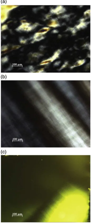
The spectra from the debris ejected from both the olive oil and the silicone oil scaifes during the first minute of polishing show traces of oil and diamond (figures 3 & 4)

contrary to their brightness in the optical absorption spectrum, and (ii) strong quantum interference between the first two excitonic reso- nances mediated by nonadiabatic

Polarization of a paramagnet by a fast high intensity magnetic field pulse : spin and phonon relaxation, phonon spectroscopy... POLARIZATION OF A PARAMAGNET BY A FAST