COLLAPSE OF THE INTER-ELECTRODE BREAKDOWN ARC IN THE MAGNETIC FIELD DIRECTION
by D. A. Oliver
by D. A. Oliver
ABSTRACT
A two-dimensional inter-electrode breakdown arc which is uniform in the magnetic field direction is shown to be unstable.
The growth time for the instability is of the order of the arc
development time. It is unlikely that a fully steady
two-dimen-sional arc is ever established. The relationship of the instability
to recent experiments revealing an inherently three-dimensional
I. INTRODUCTION
In previous studies [Refs. (1), (2), (3), (4)] a two dimensional
model of inter-electrode breakdown has proven adequate in predicting
some features of the breakdown process. In particular, excess Joule
heating of the plasma near the insulator surface due to the Hall
effect has been identified as the driving mechanism for breakdown.
Detailed MHD boundary layer calculations have predicted Hall voltage
saturation and two-dimensional arc formation with average current
densities of many tens of amp/cm2 . These predictions of Hall voltage
saturation appear to match those measured in Ref. (5). The question
of three-dimensionality, particularly collapse and pinching of the arc
in the magnetic field direction, still remains however.
In the present report this question is examined. We shall show
that the fully developed two-dimensional sheet arc overlaying the
insulator surface is unstable to disturbances in the magnetic field
direction for typical MHD generator breakdown conditions. Further,
this instability has a growth time of the order of the turbulent heat
diffusion time through the breadth of the arc. For typical MHD
generator operating conditions this time is of the order of 10-3 seconds
which is of the order of the growth time for the two-dimensional arc
-2-II. MODEL OF THE TWO DIMENSIONAL ARC
We shall model the two dimensional arc as a single zone of
concentrated current density and temperature. A typical fully
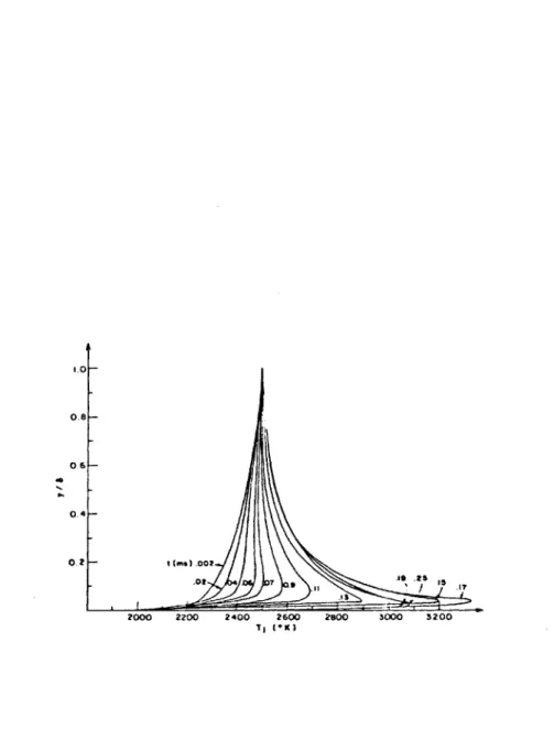
developed two-dimensional breakdown arc is shown in Fig. 1.
It can be seen that the bulk of the breakdown current is spatially
concentrated in a narrow region of breadth 6
a.
As a simplifiedmodel of this continuum profile, we shall use a discrete profile
as shown in Fig. 2. We shall assume the current vanishes outside
this zone and the temperature is essentially the free stream
temperature outside the arc zone. Inside the arc zone of breadth a the temperature and current are uniform and have the values T and J respectively.
The energy equation for the arc of breadth 6a governing the temperature T is pC = Ka(T0o-T)/(62/2) + K (T - T)/(62/2) p Dt aw w a (2.1) + K V2 T + J2/c(T) I IL D +
a
TeefctvThe convective derivitive is - - +
Dt a - h fetv
turbulent heat conduction coefficient on the outer side of the
arc is K , while the coefficient on the wall side is denoted Kw'
e CO w
The conduction coefficient in the transverse direction is K with
a2
+a2ax
+
-z
We assume that the transverse direction (y) and magnetic
field direction (z) currents vanish in the steady state so that the
only currents and fields in the steady state are J 0, E 0, Ey. These are given in terms of the inter-electrode voltage V as
x
J = a(T )E = - (T )V /. (2.2)
yo xo
where
a
and 3 are the electrical conductivity and Hall parameterrespectively. The Hall parameter is assumed constant in what follows.
The corresponding steady state temperature in the arc is T .
The steady temperature T0 is determined by the steady and uniform 2
(V. T0 E 0) solution of the energy equation (2.1) in terms of the applied voltage V and the outer (TO) and inner (T ) temperatures:
x w
a(T )62 V
T =T + 0 a 2 (2.3)
0 g (Koo+ K w)/2 '
o w 1
The temperature T is the temperature the gas would achieve in the breakdown layer in the absence of Joule heating:
T = (K T + K T )/(Ko+ K ) (2.4)
g w w w
Once the conductivity is specified as a function of the temperature, the non-linear algebraic Eq. (2.3) may be solved for the steady two-di-mensional arc temperature T0.
-4-III. STABILITY OF THE TWO-DIMENSIONAL ARC
We
now consider fluctuations in the z direction about thesteady state described in Part II. For this purpose the temperature,
current, and field are represented in terms of steady and
fluctuating parts as T(zt) = T + T'(zt) l(z,t) = J + J4$) f(zt) = E0 + E (zt) (3.1) where J 0 = X01, 0, 0), E, = (ExoEYO 0).
The Uaxwell
Equations
require thatE 0 z
(3.2) E' = E' = 0
x y
The Ohm's Law for the fluctuations is
J' + J' = a E' + G'E x y O x XO -3J' + J' = a E' + G'E x y y yo J = a E' + G'E z o z zo (3.3)
It follows that
= E
a'
x xo
J'= J' = E' = 0
y z z
The fluctuating Joule heat is then (to first order in J', a') x
2 T
~'xoxo
a' =*xoa
(-) =2 o J - (-)
a
Ga
CY0 x xa
Y0as
Cr0as a
Y0 Cf0(34 (3.4)The fluctuating first order part of the energy equation (2.1) may now
be expressed as J2-XO 2(3 ln a DT' a 0T 0 a T 0n 1 T' 42 T' DT' _ a o -lT'+ Dt (K + K )/2 + 3z 00 w (3.5)
The conductivity fluctuation is represented in terms of the temperature
fluctuation as
=' 0 ln a T'
a D n T o T0
The time T is the average effective diffusion time through the layer 6a
pC (62/2)
T p a
(K
o
+ K ) wwhile al is the turbulent diffusivity in the z direction.
In the absence of z direction heat conduction (ct= 0), the stability condition for growth of fluctuatiorv is readily established from Eq. (3.5)
as J2 ___ 3ln a 2( XO) 62/(K+K )) >1 (3.6) aT a w lnTo 00o
-6-This condition expressed in terms of the breakdown voltage V is x
2 a(1 ) 2 62 / (K + K )( i n Ty . (
f-) 1 a ao w 3 In T)~ (3.7)
The stability condition can also be expressed in terms of the steady state
temperature elevation as
T - T 9dI
T 0 a n T o
~T'
ln~o(3.8) (38For typical two-dimensional breakdown we may have T = 1700*K, T = 3000 *K,
g 0 (3 ln a/3 In T) 10 so that T ) T9( a In x) T 3 In T 0
The stability condition is therefore readily violated.
The growth time of an unstable z direction fluctuation is
T-undamped T 0 - T 9 ) ln
-T 3 ln T/O The time, T, may also be expressed as
1 (6/6)2
N s(u/D)
st
where Nst is the Stanton number band on the definition
(K + K )/2
N
st DpC u
p
For 6 /6 ~ 1/4, u = 250 m/sec, 6 = 1 cm, D = 10 cm, N = 0.02, the
a st
time T is approximately 0.3 ms.
If axial conduction is included, the fluctuation may be represented
= e (t/T'+ ikz)
where k = 2Tr/X is the wavenumber of the mode of wavelength 2. The growth
time is then given in terms of k as
(T' ) -1= T ( Tln T - 1
]
, -i -l2
(T
)
= T d - kundamped
Wavelengths shorter than X it given by rin
( T0 T 9) ( In (G _
2 T 0 aln To
41T
o
crit
will be damped by axial diffusion. Assuming a 4o, the cut-off wavelength
-8-IV. CONCLUSION
We conclude that magnetic field direction collapse of a
two dimensional inter-electrode arc should occur on a time scale
of the order of the breakdown time scale itself. Hence it is
unlikely that a uniform two-dimensional arc is ever established
in an inter-electrode breakdown. Rather, a series of arc streamers
distributed in the magnetic field direction is more likely. If
these streamers are numerous and somewhat uniformly distributed
then the aggregate begins to resemble a two-dimensional arc once
again with 'fine structure' in the magnetic field direction. Two
dimensional breakdown theory of Refs. (1), (4) should again be
generally descriptive of such a situation. (Since the streamers
are non-uniform in the magnetic field direction anamolous
impedance effects due to the Hall affect are not possible.)
It should be noted that all wave lengths save the shortest
to be cut off by turbulent diffusion in the z direction are permitted
to grow equally fast; hence many wave modes and numerous resulting
streamers are possible. On the other hand if some selection mechanism
(outside that purely operative in the gas) were to select only
the longest wave lengths, then only one or two resulting streamers
would be likely and the breakdown would become essentially
three-dimensional. Preliminary evidence from Stanford [Ref. (6)]
indicates that the formation of a single streamer is intimately
associated with the heat-up of the insulation material itself.
It is therefore possible that the thermal dynamics of the insulator
providea selection mechanism for a single dominant unstable mode.
1. Oliver, D. A., The Prediction of Inter-Electrode Breakdown in
MHD
Generators, M.I.T. Gas Turbine Lab. Report No.116 (March 1974). 2. Oliver, D. A., "Time Dependent Phenomena inMHD
Generators,"Proc.
Ist
Joint Soviet-American Colloquium on Problems of MHD Power Generation, Moscow (Feb 1974).3. Oliver, D. A., "Theoretical Observations on Electrical Breakdown in
MHD
Generators," Proc. 2nd Joint Soviet-American Colloquium on Problems of MHD Power Generation, Washington, DC (June 1975).4. Oliver, D. A., "Inter-Electrode Breakdown on Electrode Walls Parallel and Inclined to the Magnetic Field," Proc. 6th Int'l Conf. on MHD Electrical Power Generation, Wahsington, DC (June 1975).
5. Burenkov, D. K., et al., "Investigation of the Inter-Electrode Breakdown in a Channel of MHD Generator of the U-02 Installation," Proc. 2nd Joint Soviet-American Colloquium on the Problems of MHD Power Generation, Washington, DC (June 1975).
6. Unkel, W., Kruger, C. H., and Koester, J. K., "Axial Field Limitations in MHD Generators," Proc. 6th Int'l Conf. on
MHD
Electrical Power Generation, Washington, DC (June 1975).i.0- 0.6- 06- 0.4-0.2- 1 (ms).002 .02 7 g 9, II '1 5.17 .13 2000 2200 2400 2600 2800 3000 3200 T1 (*K)
Figure 1: Calculated Two-Dimensional Continuum Breakdown Arc Profile (Ref. 4)
T 00 Ik t I-x UN
I
V. T a Lx k-. r Z .77 / - Z
Figure 2: Discrete Model of Two-Dimensional Arc ja T w T 00 T a E) x T w