HAL Id: hal-00336997
https://hal.archives-ouvertes.fr/hal-00336997
Submitted on 5 Nov 2008
HAL is a multi-disciplinary open access
archive for the deposit and dissemination of
sci-entific research documents, whether they are
pub-lished or not. The documents may come from
teaching and research institutions in France or
abroad, or from public or private research centers.
L’archive ouverte pluridisciplinaire HAL, est
destinée au dépôt et à la diffusion de documents
scientifiques de niveau recherche, publiés ou non,
émanant des établissements d’enseignement et de
recherche français ou étrangers, des laboratoires
publics ou privés.
Enhancing Diagnosis Ability for Embedded Electronic
Systems Using Co-Modeling
Manel Khlif, M. Shawky
To cite this version:
Manel Khlif, M. Shawky. Enhancing Diagnosis Ability for Embedded Electronic Systems Using
Co-Modeling. SPRINGER, pp.6, 2007, ISBN 978-1-4020-8736-3. �hal-00336997�
Enhancing Diagnosis Ability for Embedded
Electronic Systems Using Co-Modeling
Abstract- This paper describes a new modeling and simulation approach in order to enhance the diagnosis ability of an electronic embedded system, including in the automotive field. Our modeling approach integrates the hardware specifications to the functional model in order to establish better system observation. It is based on hardware/software (HW/SW) co-modeling with multilevel of granularity.
To reach this objective, we have set up a relationship between the desired diagnosis accuracy and the level of granularity of the HW/SW co-model, for every Electronic Computing Unit (ECU). Our contribution allows the attribution of the right co-simulation hierarchical level by attributing the right simulation accuracy, for each function under observation.
Index Terms- hierarchical modeling, HW/SW co-modeling, real time simulation.
I. INTRODUCTION
The technological development encourages the car manufacturers to propose advanced driving assistance functions that involve more than one computing unit. In fact, a computing unit uses information issued from sensors or other computing units, yielding a “system with distributed functions”. In a vehicle, the functions are sometimes distributed on several components or subsystems (computing units, wires, sensors, actuators…), communicating with several interconnection networks [1].
However, one of the disadvantages of this distribution is the difficulty of the real time supervision to detect and localize a
fault, especially electronic hardware faults. To bring out the
advantages of a highly distributed architecture, we propose a modeling methodology that benefits from the existing link between the software and the hardware platforms.
Our contribution in this paper is to enrich the functional models with hardware characteristics, at the very first phase of establishing the diagnosis models (system observation), in order to reproduce the appropriate behavior of the system in a set of comprehensible models showing at the same time the hardware and the software behaviors.
To present our contributions, this paper is structured as follows:
First, we present the need of HW/SW co-modeling for embedded electronic systems supervision. Then, we present the related works done in the field of the HW/SW co-design [2].
In section IV, we show a relationship between the required accuracy for fault detection and the level of granularity in the HW/SW co-model, in order to find an appropriate compromise between fault detection accuracy and simulation speed. In section V, we use SystemC as a working environment for the hierarchical HW/SW co-modeling of our embedded electronic architecture. We present the results in sections VI and VII.
Finally, in the last section we conclude this paper and present our future works.
II. HARDWARE/SOFTWARE CO-MODELING FOR EMBEDDED ELECTRONIC SYSTEMS
Car manufacturers usually employ software models expressing the embedded functions to make fault detection and diagnosis. However, when the hardware architecture reaches a complex level of functional distribution, it becomes difficult to a diagnosis designer to maintain the HW/SW link for each function or sub-function of the system in the diagnosis model.
We believe that every sub-function has a link with at least one hardware sub-component, and a hardware fault appears in the system as a functional fault. Therefore, if we detect the functional fault we can localize the hardware fault if we know exactly the existing link between the sub-function and the hardware sub-component.
The electronic distributed architecture that we study is embedded on board of a truck. It is composed of a set of ECUs connected by the interconnection bus CAN (Controller Area Network) [3]. Every ECU is composed of a processor, a memory, a CAN interface and eventually Inputs/Outputs interfaces.
Manel KHLIF, Mohamed SHAWKY Heudiasyc - UMR 6599
Université de Technologie de Compiègne Centre de Recherches de Royallieu
BP 20529
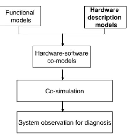
Functional models Hardware description models Hardware-software co-models Co-simulation
System observation for diagnosis
Fig. 1. Hardware and software models for system observation for diagnosis.
Some existing techniques of fault detection and diagnosis, especially of electronic systems, are based on functional simulation of the real controlled system, running on a prototyping platform, in parallel with the real time operation of the system [4]. These techniques do not describe hardware components (i.e. architecture and behavior description) and need to be more accurate by expressing simultaneously both hardware and software behaviors, in order to lead to more accurate results of fault detection (Fig. 1).
We aim at modeling the functional distribution on the hardware architecture, in a coherent way, offering the ability to be connected to other models that may be proposed by different manufacturers of such heterogeneous electronic system. Our approach should allow the supervision system designer to integrate different models to simulate and test the system.
In the next section we present research works close to our objectives, and that use mix hardware and software information for simulation.
III. HW/SWCO-DESIGN
Hardware/software co-design is a set of methodologies and techniques specifically created to support the concurrent design of both systems, effectively reducing multiple iterations and major redesigns [2].
Within the context of co-design methodologies, concurrent hardware and software techniques have been proposed in the literature employing for example SpecC to add more details at the specification level [5]. The adoption of various formal languages for co-simulation, like SDL and C [6] is mainly used for the design of reactive systems, following the stimulus–response paradigm of behavior, like telecom systems such as wireless protocols employing different and
standardized formalisms. On the other hand, functional models compatible with HDL (Hardware Description Language) models [7] are needed to get accurate hardware specifications using for example RTL (Register Transfer Level) level of modeling. However when it concerns HW/SW co-design for providing observation and verification, system’s behavior and properties are specified in a single formal language such as in [8] and [9].
Even though Hardware/Software co-design is receiving a lot of attention in literature, most published works do not address model-based diagnosis for electronic systems. In this paper, we are not interested by dependability analysis (fault simulation, estimation of optimal diagnostic strategies, etc,), but we focus on co-modeling of the appropriate behavior of an electronic system for co-simulation oriented diagnosis.
IV. MULTILEVEL OF GRANULARITY CO-MODELING
Multilevel of granularity is a hierarchical view of a system, expressing in each level a degree of details and accuracy.
Our objective is also to develop a relationship between the accuracy of the expected on-line fault detection and the level of granularity of hardware/software co-modeling (Fig. 2).
Sub-system co-modeled with a “g” granularity level Functional model A fault Hardware description model The hardware source of fault
Fig. 2. Relationship between a sub-system HW/SW co-model and hardware source of fault.
As a first step, we have to model the hardware architecture as a set of hardware sub-components. Then, we have to model the software platform as a set of sub-functions allocating them to the modeled hardware sub-systems.
As a second step, we define a scale of criticality levels for the sub-functions. Then we allocate a granularity level of modeling to every criticality level, and hence, each sub-function is co-modeled with a corresponding granularity level (Fig. 3).
The more accurate the level of granularity, the longer the simulation time is. Thus, it is possible to switch between two or more levels of granularity according to the criticality level of eventual faults and to the diagnosis system needs (e.g.: functions priorities). This is the main advantage of our approach of modeling at various levels of granularity.
s-f 1.2 s-f 2.3 s-f 3.1. . . ECU1 ECU 2 ECU 3 . . Sub-system co-model (with “g” granularity level)
List of faults of s-f 1.2 (s-f 1.2 has “p” function priority) “g” <->“p” “p” <->“a” Accuracy “a” of supervision
Fig. 3. Granularity-accuracy relationship.
V. WORKING ENVIRONMENT
A. SystemC
One of the most promising SystemC advantages is HW/SW co-modeling to develop virtual platforms, because it supports a unified language of HW/SW modeling [10].
We have selected SystemC as a working environment because it has many advantages:
• SystemC allows hierarchical modeling to express the
multilevel of granularity modeling
• It allows HW/SW modeling with the same language
• The models could be easily connected to any other
hardware models [11], or functional models (e.g. in Simulink) [12][13][14]
• SystemC environment includes also a simulator: it consists
of a C++ library and an event-based motor for simulation
• Any C or C++ library can be included in a HW/SW
co-model
Hence, we can describe the appropriate behavior of the electronic embedded system with different levels of hierarchy. Thus, every sub-system that should be under supervision can be hierarchically co-modeled.
B. Cycle Accurate modeling
SystemC Transaction-level modeling (TLM) is a high-level approach to model digital systems where details of communication among modules are separated from the details of the implementation of functional units or of the communication architecture [15].
A Cycle Accurate (CA) model is a TLM model that represents the stage of communication refinement, in which communication is modeled accurately down to the level of bus cycles, and even clock cycles. CA modeling allows hardware verification, evaluating the state of every component in every cycle and running software device drivers. CA simulation speed varies between 10 and 100 KHz. A CA model consists of a set of processes that run once per cycle. This fits with the use of SC_METHOD processes and non-blocking calls.
Fig. 4 shows that TLM projects do not require a lot of effort and time to be correctly modeled compared to RTL projects. In fact, a Cycle Accurate project may need approximately half of the time compared to an RTL project for its realization.
For these advantages, we have used the CA level to co-model our HW/SW platform as shown in the next section.
Fig. 4. Time and effort spent for RTL and TLM use cases [16].
VI. MULTILEVEL CO-MODELS
A. Multilevel of granularity using TLM modeling
We co-modeled with TLM, hierarchically, each HW/SW sub-system beginning with the highest level of granularity. Thus, on each level of granularity, we find a set of models representing at the same time the functional behavior and the hardware architecture.
In the next sub-sections we show an example of TLM model representing the embedded electronic architecture.
B. ECUs and CAN bus modeling
The whole architecture consists of n ECUs communicating through the CAN network [3]. In this part of the work, we have modeled the CAN protocol real-time behavior to realize communications between ECUs models. We have simplified the details to ease the modeling; by implementing a virtual arbiter in the bus. With the Transaction modeling, the communication between components is described as function calls.
Each ECU is master and slave at the same time and has one bidirectional port in each module. It is used to send orders to the bus (Requests) and getting data and information from the bus (Responses) (see Fig. 5). Each ECU that wants to send a message sends a request to the bus. If at least 2 ECUs request a bus transmission at the same time (i.e. in a time shorter than a bus cycle), the bus arbiter selects the most important message by comparing arbitration fields in the two messages.
Only one clock is used for all processors when the level of granularity is high and the accuracy of the model for simulation is set to the ECU clock cycle.
It is important to note that full CAN protocol is used only in models with high level of granularity, expressing transactions between ECUs. With a more accurate level of granularity, the
processor and the memory models of every ECU are wrapped into SystemC modules in order to communicate with other devices such as CAN controllers. Anyway, the transactions are kept cycle accurate.
Master Master Master Slave Slave Slave Arbiter ECU1 ECU2 ECU3
Channel + communication port Master Master Master Slave Slave Slave Arbiter ECU1 ECU2 ECU3
Channel + communication port
Fig. 5. CAN bus TLM model.
C. HW/SW models interfacing
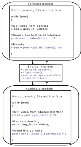
The communication between hardware modules and software modules should be done through message exchange. Messages should be exchanged through a shared interface between the two sides, implementing the needed methods for message exchange and eventually using blocking calls (Fig. 6).
We have co-modeled in SystemC a sub-function of Lane Keeping [17]; a given function from a truck manufacturer. The Lane Keeping should keep a truck centered in the current lane of a highway, detected by an embedded camera. Fig. 6 shows also the example of the embedded camera software that sends the acquired videos to an ECU (the hardware module), which is responsible of filtering all extra images from the video sequence, to get only the video sequence of the highway.
D. Interfacing SystemC co-models
A systemC co-model may be the result of a higher level system level modeling, such as SySML [18] or AADL (Architecture Analysis and Design Language) [19]. A SystemC co-model can also integrate other functional models in Simulink [12] for SW description and VHDL [20] for HW description models. We show also that co-simulation is possible by using interfaces between the heterogeneous simulators (Fig. 7). For example, [11] presents some results of design practice of HW modules; co-simulation and synthesis are combined to achieve higher abstraction levels in the design. The SystemC-VHDL co-simulator tool is also based on a SystemC/C++ front-end developed to support the co-simulation between VHDL and SystemC. Another example of co-simulation tool is shown in [13] using Simulink with SystemC in a cycle-accurate context.
// m o d u le u s in g S h a r e d I n te r f a c e w h ile ( tr u e ) { // G e t v id e o fr o m c a m e r a v id e o = a c q u ir e _ v id e o ( ) ; // S e n d v id e o t o S h a r e d In te r fa c e p o r t - > s e n d _ v id e o ( v id e o ) ; / /1 // R e s u lt s v id e o = p o r t- > g e t_ f ilt _ v id e o ( ) ; //4 } • v o id s e n d _ v id e o ( V i v ) • V i g e t _ v id e o ( ) • v o id s e n d _ la n e s _ v i d e o ( V i v ) • V i g e t _ f ilt _ v id e o ( ) S o ft w a r e m o d u le S h a r e d In te r fa c e // m o d u le u s in g S h a r e d In t e r fa c e w h ile ( t r u e ) { //G e t v id e o fr o m S h a r e d In t e r fa c e v id e o = p o r t - > g e t _ v id e o ( ) ; / /2 //L a n e s e x tr a c tin g e x tr a c tin g _ la n e s ( v id e o ) ; //S e n d filte r e d v id e o p o r t- > s e n d _ la n e s _ v id e o ( v id e o ) ; / / 3 } H a r d w a r e m o d u le
Fig. 6. HW/SW modules interfacing.
The advantage of the proposed multilevel granularity co-modeling is the possibility of establishing a link between a HW/SW co-model and another type of models in any level of detail and having several possibilities of co-simulation speed for fault detection.
System design and modeling (e.g. AADL, SySML)
Partitioning interface SW HW Multilevel of Granularity HW/SW co-models (e.g. SystemC) Functional models (e.g. Simulink Matlab) Hardware description models (e.g. VHDL Verilog Simulation System observation
Simulation Co-simulation Simulation interface Co-simulation interface 1 2 3 4 5
VII. CO-SIMULATION FOR DIAGNOSIS
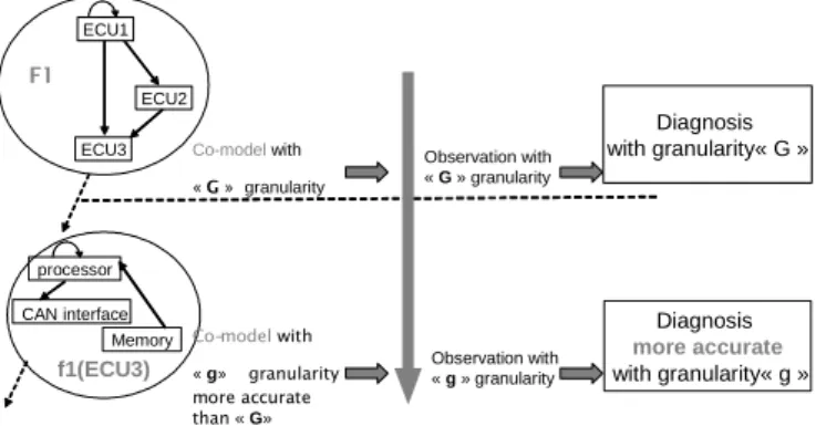
The supervisory system can simulate the co-models beginning with the highest level of the hierarchy in order to observe the electronic system. In case of incoherence detection in a given level of the hierarchy, our approach brings the advantage of co-simulating the system with a more accurate level in order to increase the accuracy of incoherence localization (Fig. 8). f1(ECU3) processor Memory CAN interface Co-modelwith « G »granularity Co-modelwith « g» granularity more accurate than « G» Diagnosis with granularity« G » Diagnosis more accurate with granularity« g » Observation with « G » granularity Observation with « g » granularity ECU2 ECU3 ECU1 F1
Fig. 8. Multilevel of granularity co-simulation.
It is important to add that this approach of modeling for diagnosis is simple to implement when the embedded functions are cyclic, as progressive and repetitive simulations may be done with real input values. For this reason, we have tested our approach with the Lane Keeping (LK) system described earlier (Fig. 9).
This system supplies a wheel angle set point sent to the ECUs, and does not require any driver intervention. At any time, the driver can deactivate the LK function. The LK system recognizes the lane markings using an embedded camera. In case of fault detection with a high level of granularity co-simulation, the diagnosis system should make sure that the electronic embedded system may suffers from a fault by co-simulating and testing the same sub-function (e.g. Highway videos capturing) with a more accurate level of granularity until reaching the sub-system eventual source of fault.
Fig. 9. Lane Keeping function [14]
VIII. CONCLUSIONS AND PERSPECTIVES
This paper has presented a co-modeling technique with multilevel of granularity under SystemC for electronic systems. Cycle accurate models of the CAN bus, CAN
interfaces and ECUs including memories and processors has been co-modeled with different levels of granularity.
The impact of a multi-granularity HW/SW model for the hardware real-time fault detection has been shown.
This result shows that such modeling method is suitable to simulate distributed real time HW/SW architecture, especially electronic architectures and allows the supervision designer to re-use the co-models in embedded simulations for real time supervision or to simulate and test the system off-line.
As future work, we aim to extend the multilevel granularity modeling to other computing platforms, like SoC (System On Chip) for example; a technology which is gaining interest for car manufacturers. The TLM is very suitable to model the architecture of a SoC, in order to enable development of the embedded software in advance of the hardware, and to carry out analyses earlier in the design cycle.
ACKNOWLEDGMENT
We would like to thank Amanie Ghannoum and Janine Alhassan for their contribution to this work.
REFERENCES
[1] Paret D. 2007. Multiplexed Networks for Embedded Systems: CAN, LIN, FlexRay, Safe-by-Wire, Wiley, ISBN: 978-0-470-03416-3 [2] Giovanni. De Micheli, Rolf. Ernst. Readings in hardware/software
co-design. 2001. Embedded System Computer
[3] Paret D, 1999. Le bus CAN description : de la théorie à la pratique. Dunod , ISBN-10: 2100047647, ISBN-13: 978-2100047642.
[4] Hamscher W. and al, 1992. Readings in model-based diagnosis. Morgan Kaufmann, isbn: 1-55860-249-6, San Francisco, CA, USA.
[5] Gajski D-D. and al, 2000. SpecC: Specification Language and Methodlogy, Kluwer Academic Publishers.
[6] Gioulekas, F. and al, 2005. Heterogeneous system level co-simulation for the design of telecommunication systems. Journal of Systems Architecture. 51, p. 688-705.
[7] Wong, S.Y, 1998. Hardware/software co-design language compatible with
VHDL. IEEE, WESCON/98, Anaheim, CA, USA, p. 78 -83.
[8] Csertan G. and al, 1994. Modeling of Fault-Tolerant Computing Systems. In Proceedings of the 8th Symposium on Microcomputers and Applications, uP'94, Budapest, Hungary, p.78-83.
[9] Csertan G. and al, 1995. Dependability Analysis in HW/SW co-design. In Proceedings of the IEEE International Computer Performance and Dependability Symposium, IPDS'95, Erlangen, Germany, p. 316-325. [10] Grötker T. and al, 2002. System Design with SystemC. Springer,
Chapter 8, p. 131. ISBN 1402070721.
[11] Bombana, M.; Bruschi, F. 2003. SystemC-VHDL co-simulation and synthesis in the HW domain. Design, Automation and Test in Europe Conference and Exhibition, pp. 101-105, Messe Munich, Germany. [12] Warwick C, “SystemC calls MATLAB”, MATLAB Central, March
2003, http://www.mathworks.com/matlabcentral/
[13] Czerner F. And Zellmann J. 2002. Modeling Cycle-Accurate Hardware with Matlab/Simulink using SystemC. 6th European SystemC Users Group Meeting (ESCUG). Stresa, Ilalia.
[14] Boland J-F and al. 2004. Using Matlab and Simulink in a SystemC verification Environment. 2nd North American SystemC User’s Group. Santa Clara, CA, USA
[15] Cai L. and Daniel G, 2003. Transaction level modeling: An overview. In Hardware/Software Co design and System Synthesis, Report 03-10, Center for Embedded Computer Systems, University of California, p. 466-471.
[16] Ghenassia, F. (ed.), 2005. Transaction-Level Modeling with SystemC. TLM Concepts and Applications for Embedded Systems. Springer. ISBN 0-387-26232-6.
[17] Claeys X. and al, 2003. Chauffeur Assistant Functions. Report restricted
to RENAULT TRUCKS, Contract number IST-1999-10048, Lyon,
FRANCE.
[18] SysML Partners. 2005. Systems Modeling Language (SysML) Specification. Version 1.0 alpha. SysML.org
[19] http://www.axlog.fr/aadl/http://www.mathworks.com/products/simulink/ [20] Cote, C.; Zilic, Z. 2002. Automated SystemC to VHDL translation in hardware/software co-design. Electronics, Circuits and Systems, 2002. 9th International Conference on Volume 2, Issue , pp. 717-720, Dubrovnik Croatia.
![Fig. 4. Time and effort spent for RTL and TLM use cases [16].](https://thumb-eu.123doks.com/thumbv2/123doknet/14214476.482534/4.892.503.789.269.419/fig-time-effort-spent-rtl-tlm-use-cases.webp)