READ THESE TERMS AND CONDITIONS CAREFULLY BEFORE USING THIS WEBSITE. https://nrc-publications.canada.ca/eng/copyright
Vous avez des questions? Nous pouvons vous aider. Pour communiquer directement avec un auteur, consultez la
première page de la revue dans laquelle son article a été publié afin de trouver ses coordonnées. Si vous n’arrivez pas à les repérer, communiquez avec nous à [email protected].
Questions? Contact the NRC Publications Archive team at
[email protected]. If you wish to email the authors directly, please see the first page of the publication for their contact information.
Archives des publications du CNRC
This publication could be one of several versions: author’s original, accepted manuscript or the publisher’s version. / La version de cette publication peut être l’une des suivantes : la version prépublication de l’auteur, la version acceptée du manuscrit ou la version de l’éditeur.
Access and use of this website and the material on it are subject to the Terms and Conditions set forth at
Manual on Metric Building Drawing Practice
Strelka, C. S.; Loshak, L.; Torrance, J. S.
https://publications-cnrc.canada.ca/fra/droits
L’accès à ce site Web et l’utilisation de son contenu sont assujettis aux conditions présentées dans le site
LISEZ CES CONDITIONS ATTENTIVEMENT AVANT D’UTILISER CE SITE WEB.
NRC Publications Record / Notice d'Archives des publications de CNRC:
https://nrc-publications.canada.ca/eng/view/object/?id=70e6766a-ce0a-4422-a0dd-f3108493a37a
https://publications-cnrc.canada.ca/fra/voir/objet/?id=70e6766a-ce0a-4422-a0dd-f3108493a37a
Manual on Metric
Building Drawing Practice
PREPARED BY
C.S.STRELKA,
L.
LOSHAK ANDJ.S.TORRANCE
MEMBERS OF THE WORKING GROUP,
SUBCOMMITTEE ON DESIGN AND CONSTRUCTION,
INTERDEPARTMENTAL COMMITTEE FOR METRIC CONVERSION
Conseil national de recherches du Canada
MAN U A L
o
N
MET RIC
B U I L DIN G
D RAW I N G
Prepared by
P RAe TIC E
C.S. Strelka, National Research Council of Canada
L. Loshak, Central Mortgage and Housing Corporation
J.S. Torrance, Department of Public Works, Canada
Members of the Working Group, Subcommittee
on Design and Construction,
Interdepartmental Committee for Metric Conversion
Special Technical Publication No. 3
of the
Division of Building Research
Price:
$3.00
Ottawa, April 1976
Revised
June 1977
The Canadian construction industry is preparing for conversion to
the metric system beginning in January 1978.
This manual, prepared by
the Working Group of the Subcommittee on Design and Construction of the
Interdepartmental Committee for Metric Conversion, has been developed to
assist in the preparation of proper construction drawings that are so
essential to a smooth transition.
This Manual is a basic tool for metric conversion.
The first
three Parts explain what is involved in this conversion.
Part 4 gives
a step-by-step procedure for the production of metric drawings; the
following Parts will assist, it is hoped, in design decisions and offer
help with the actual act of "translating" a design approach to metric.
One of the main responsibilities of the Division of Building
Research is to serve the Canadian construction industry.
The Division
was pleased, therefore, to have one of its members serve on the Working
Group responsible for preparing this Manual and to arrange for its
pub 1ication.
It is hoped that this Manual will be of assistance to those in the
construction industry who are concerned with the conversion to metric.
Comments on the Manual will be welcomed.
Ottawa
April
1976
C.B. Crawford
Director
Division of Building Research
National Research Council of Canada
texts, not only Canadian but also those issued by other countries that
have recently converted to SI.
Although these have not been cited in
the text, the authors wish to acknowledge the information gained from
the following references:
Metric Conversion in Building and Construction, 1972, Standards
Association of Australia.
Metric Data for Building Designers, 1975, Standards Association of
Australia.
AJ Metric Handbook, 1969, The Architectural Press, London.
CAN-3-Z234.l-76. Metric Practice Guide.
CAN-3-Z234.2-76, The International System of Units (SI).
CAN-3-A3l.M-75, Series of Standards for Metric Dimensional
Co-ordination in Building.
CSA B78.3 (draft) Building Drawings.
CGSB 88-GP-20M, Standard for Scales (Ratios) for Charts, Maps, and
Plans in Metric (SI) System.
Metric Monitor and various booklets published by the Metric
Commission, Ottawa.
The Working Group also wishes to credit the source of the following
tables that are reproduced in this Manual:
Tables Nos. 8.1 to 8.4 and 8.6 to 8.14 from Metric Conversion in
Building and Construction, 1972, Standards Association of
Australia;
Tables Nos. 6.1 to 6.4 from Metric Data for Building Designers,
1975, Standards Association of Australia.
PAGE
PART
1
INTRODUCTION
1
PART
2
METRIC CONVERSION
4
PART
3
SI METRIC
6
PART 4
DRAWING PRACTICE
10
PART
5
DIMENSIONAL CO-ORDINATION
51
PART
6
AN1HROPOMETRIC DATA AND INTERNAL CIRCULATION
53
PART
7
EXTERNAL CIRCULATION
65
PART
8
CONVERSION FACTORS AND TABLES
69
PART
9
SI UNITS FOR USE IN DESIGN AND CONSTRUCTION
80
APPENDIX A
NAME AND ADDRESSES OF MEMBERS OF METRIC
CONVERSION COMMITTEES
(v)
1.1 GENERAL
PART
1.
INTRODUCTION
In the White Paper on Metric Conversion, released in January 1) ,the Covernment of Canada responded to numerous representations from widely diverse segments of the nation
(Canadian Construction Association, Engineering Institute of Canada, Canadian Council of Professional Engineers, Canadian Chamber of Commerce, Royal Architectural Institute of Canada, and Canadian Teachers' Federation to name only a few of the organizations that
presented briefs on this matter). All these groups realized the desirability and inevita-bility of Canada's "going metric" in conformity with the world-wide trend exhibited in the 1960's and 70's by which time almost all nations were committed to this international system of weights and measures. General policy, set out in the White Paper, adopted the International System of Units (SI) as the basis for metric conversion in Canada. At the same time the Weights and Measures Act was revised to include the SI units, thus making them legal in Canada.
1.2 1>lETIUC COMMISSION
To achieve one orderly change to the metric system of measurement, the Federal Government, by Order in Council in June 1971, established the Ne tric Commission to co-ordinate and stimulate metric conversion throughout the nation's economy. The Commission, in turn, established eleven Steering Committees, each responsible for co-ordinating a group of economic sectors wit.h related interests. A chart of the distribution of the various engineering industries sectors in the Steering Committee is shown on rig. 1.1. From this chart it is obvious that although the building industry as such comes under Steering Committee 5, the complexity of the industry necessitates
co-operation with other sectors. There fo re , aside from the regular Sector Committee work in Steering Committee 5, intersectoral links were established to serve the interests of the building industry. To further co-ordination of metric conversion in the public
service sector, two other committees were established: an Interdepartmental Committee for Metric Conversion (ICMC) Subcommittee on Design and Construction, and the
Intergovernmen-tal Design and Construction Committee on Metric Conversion (IllCC) (provincial level). (Names and addresses of members of Committees concerned with metric conversion in Canada's construction industry are included in Appendix A.)
1.3 M-DAY
By consensus of the representatives of the Canadian construction industry, 1 January 1978 has been selected as "M-Day" for construction. This is the first day of Metric Construction Year -- the year in which the Canadian construction industry will work mainly in the SI system. Following M-day, drawings and specifications will be prepared in metric terms and materials or components that are required in metric sizes will become available. A timetable bar chart for metric conversion prepared by Sector 5.01, Construction, is shown on Fig. 1.2.
••
STEERING COMMITTEE #2
I
[
STEER 1NG COMMI TTEE # 18 i C AIR TRANSPORT
o [' C RAILWAY TRANSPORT
B C
I
WATE R TRANSPORTB C ROAD 6 URBAN TRANSPORT
B C '" TEOROLOGY
セ Mセl
WOR'ING GROUP ON TARIFFS- - - - II 63.01 12 F 63.02 11 F 63.03 12 F 6J.04 12 F セNセ 12 F 63.06 12 F 63.07 II F セNセ 12 F A - 8ERRY J. B - 80lSVERT C. C - DREYERB. o -ECCLESTONE G. E - SPARKESE. F - TALWAAR K. TO PLANN I NG MANAGERS SECTOR TITL£ FORESTRY
B.17 UR8AN FORESTR' AR80RICULTURE
WOOD (INCL. SUB-COMMITTEE)
B.21 SOFT WOODluセer
B./2 HARWOODluセer ! FLOORING
B.13 PANEL PRODUCTS
B.24 SASH. OOORS& MILLWORK
8.25 LAMINATING
セN 26 PALLETS
8.27 PRESERVATION
B.1B POLES! PILING
B.29 SHINGLES
FURN I TURE&FI XTURE S
PAPER& ALLIED IND. PRINTING & PUBLISHING TEXTILES CLOTHING LEATHER (FOOTWEARI JEWELR' SPORTING GOODS TO'S
BRUSH. BROOM8. fo(W LUGGAGE & LEATHE R GOODS
STEERING COMMITTEE #8 STEERING COMMI TTEE #7
STEERING COMMITTEE # 9
HEAL TH ! wELFARE AMUSEMENT & RECREAT ION
ARTS&CULTURE
SERVICES TO BUSINESS MANAGEMENT ACCO"ffiGATION & FOOD SER"CES RET AI L. HOME ECONO"I CS& CONSUMERS LABOUR ORGAN I1ATlONS
PERSONAL SERVICES
ELEMENTAR' 6 SECONDAR, SCHOOLS POST SECONOAR' NON-UNIVERSITY EDUCATION UNIVERSITIES! COLLEGES STEERI NG COMMITTEE #10 A A A A A A A
: I
A A A A A 7 A 7 A 7 A 2 0 2 0 2 0 5 0 5 0 2 0 5 0 5 0 9.10 9.21 9.21 9.30 9.40 9.50 9.60 9.70 B.20 B.JO B.4S 10.01 10.03 10.04 ASSICJl"lNTS OF SECTORS I -ALPERS P. 9 -EARLE J. 2 - BENNETTJ. 10セ FRIEDMAN I.3 • ROCKBURN( C.A. 11 -rANAPATHY N.
4 - CRAIG B. 12 - GULAS G.M.
5 - OEACHMAH R.J. 13 - SWAIN G.
6 - MANSOUR [. 14 - WASSINK 8.
7 - OESBARATS G. IS - 8RIGHT R.
R _ nnw H ,. - TROTTIER
TO SECTOR PLAN MANAGERS
セ\AjMBG ...
SECTOR 110.
セ セ
,it-"'-';セ
N LL Mエ セG|NセBB JLLGKセ ・NLLLセ
q"""
SECTOR STRUCTURE APPROVED 8Y THE "'TRIC COMMISSION SEPT.15, 1976 REV.OEC.1S/1976
I
· ,
7.1{) / A[[セ
I:
A 7 'I I セ 7 ' / I セ I 7'J I , IセセエMMMM
I B.IO I : 9 9 9 9 9 9 9 9 9 9 9 9STEERING COMI TTEE #5
SECTOR TITLE
CONSTRUCTION
NON-METALLIC MINERAL PRODUCTS STRUCTURAL & ARCHITECTURAL MUAlS REAL ESTATE, LAND SURVEYORS & TOWN PLANNERS ROAD OESICJl, CONSTRUCTION & OPERATIONS
BULK GRAIN HANDLING INDUSTRY FEED INDUSTRY
paULTRY LIVESTOC' HaRTlCULTURE FISHING&FISH PRODUCTS DAIRY FARMERS SEED TOBACCO FAR1'ERS TOBACCO PRODUCTS
STEERING COM ITTEE #62 FOOD CONFECTIONER' MEAT PACKE RS OAIR' PROCESSORS FOOD PROCESSORS PET FOODS 81SCUITS EDIBLE OILS SUGAR BAKERS TEA & COFFEE MILLERS COLO CEREALS HOT CEREALS
SPICES.EXTRACTS ! FOOD COLOURING COLD 8EVERAGES,MIXES 6 DR' DESSERT MIXES CHOCOLATE DRINKS & COCOA POWDER PASTA PRODUCTS
BAKING MI XES SNAC' FOODS RICE
WORKING GROUP ON PACKAGING
STEERING CONMITTEE#63 -BEVERAGES DISTILLED SPIRITS 8REWERIES SOFT DRINKS WINE LIQUORcommissioneセs MINERALwateセ PRODUCERS
FRUIT JUICE INDUSTRY CIDER I D E 10 E 10 E 10 E 10 E II F 12 F 12 F 12 F 12 F 11 F 12 F 12 F 11 F 1/ F 12 F 12 F 12 F 12 F 12 F 12 F 12 F 12 F 12 F 11 F 12 F 5.01 5.02 S.OJ 5.05 5.06 62.02 61.03 62.04 61.05 61.06 61.07 61.0B 62.09 62.10 62.11 61.13 62.21 61.12 62.13 61.24 62.2S 62.26 62./7 62.28 62.29 62.50 セGエMイNNZL\NNアNN ':!.-Q;. セ 1>'" SECTOR NO. ... ",,'" «: セHNZL c:.Q;-- *'-, <: BエMセ ""J<"; セB 61.01 61.02 61.0J 61.04 61.05 61.06 61.07 61.0B 61.09 61.10 II ! ')ECTOR TiTlE
KllOR VEH ICLE&PARTS K'\NUfACTURERS TRUC' BOD' & TRAILER MANUFACTURERS RAILROAD ROLLING STOC' SHIPBUILDING& BOATBUILDING
HEATING.'ENTlLATlNG.AIR CONO.& FOOD SERVICE EQUIP. 2.09 PllJ1tJING& HYORONIC HEATING
IRON & STEEL MILLS 6 F()tJN[JARIES
2.11 FASTENERS INDUSTR'
METAL STAMPING, FORMING. PRESSING. CQATING CAN MANUFACTURERS
COOKWARE & HOUSEWARES TOOLS & MEASURING DEVICES BUILDERS & HOME HARi)/ARE
FIRE FIGHTING EQUIPMENT - SMAlL ARMS - Tセunition
MISCELLANEOUS MACHINERY セ
AGRICULTURAL & CONSTRUCTION EQUIPMENT MACH I NER' & FLUIO POWE R
METAL WOR,ING MACHINES - MACHINE SHOPS TOOL& DIE SHOPS - CUTTING TOOLS
STEERI NG COMMITTEE #3
ELECTRI CAL MANUFACTURE RS
RADIO, TELEVISION. coセunicatャonL ELECTRONIC
EQUIPMENT& PARTS
AI RCRAFT & AI RCRAFT PARTS MANUFACTURERS
BUSINESS MACHINES. SCiENTIFIC 6 PROFESSIONAL EQUIPMEN COMMUNiCATIONS
HECTRIC POWER RUBBE R PRODUCTS
CHEMiCALS & CHEMICAL PRODUCTS PLASTICS INDUSTRY
WOR,ING GROUP ON SCALES IN THE RETAIL FOOD INOUSTR'
STEERING COMMITTEE #Y
MINES
PETROLEUM & NATURAL GAS INDUSTR'& SERVICES PETROLEUM REFINERIES. WHOLESALERS 6 GASOLINE SERVICE STATIONS
NATURAL GAS DISTRIBUTION & TRANSPORT NON-FERROUS METALS 1.01 1 02 1.03 1 .04 1.07 I. 20 2.JI 6 2. Jl /.JJ 3.01 13 3.02 13 2.011 6 B /05 6 B 2.06 6 B " .07 6 B lOB 14 B 14 B 2,10 15 B 15 B 2.21 15 B 1.22 14 セ 2,23 14 B 2.24 14 B 1.25 IS B 2.27 6 B J .03 1] C 3.04 13 F 3.05 lJ C 3.06 11 C 3.07 16 E 3.0B 16 E 3.09 16 E 3.10 14 F 4.01 J 4.02 3 E 4.0J 3 E 4.04 J E 4.05 3 E セGエMBZjBLアNN セセ セ 1>'" SECTOR NO. .,,,. ",,"'" / "l.'v セ OBエZZZGjセ セLセ / ..,,,<0 q".f
THIS TABLE IS BEING UP[JATED EVER' TWO /1JNTHS AS NECESSAR'
J
IIs!
'N! IJI
1M
... !.IM IJ Ilsjl.,Ni.IJIIMIIMIIJ I 'ISI1INI
AI 101 10
iFIjA J A
01°
Fi A J A,
0D
, 0"J, 5, :977 NATIONAL BUILDING CODE&METRIC SUPPLEMENT
PUBLISHED
7,REVISE.D FEDERAL PROVINCIAL8. MUNICIPAL LEGISLATION ENACTED
8. 1979NATIDNAL BUILDING CDOE PUBLISHED IN METRIC
1,CONSENSUS ON UNITS &RATrDS
2, STANDARDS CONVERSION PRIORITIES ESTABLISHED 3,1ST PR:ORITY STANDARDS PUB_ISHED
1..,2ND PRIORITY STANDARDS PUBLISHED 3RD PRJOfUTY STANDARDSPUBLISHED
SECTOR 5.01 CONSTRUCTION 24,START PUBLIC AWARENESS PROGRAM
20. staセョ TRAINING PROFESSIONAL DESIGNERS &CONSULTANT 21.START TRAINING TECHNICIANS&TECHNOLOGISTS 22,START TRAINING administrativセ PERSONNEL 23,START TRAINING onセsite PERSONNEL 19,DATA PREPARED FOR METRIC ESTIMATING
」セN START PRELIMINARY DESIGN FOR METRIC CONSTRUCTION
10, START U"DATE OFdraセings FOR METRIC CONSTRUCTION 11, INITIAL METRIC TENDERING DOCUMENTS COMPLETED 12 INf riAL MeRIC CONSTRUCTION TENDERED(M-DAY)
15. START ACQUISITION OF METRiC DRAFTING EQUIPMENT IG.START ACQUIS[T:ON OF METRIC ON-SITE MEASURING
EQUI PMENT
17,START OBTAINING METRIC PRODUCT LITERATURE 18,Bセetric MATERIALS&COMPONENTS AVAILABLE
O
NNMMMMMMヲセᆪセセEARLIEST EARLIEST LATEST
KEY EVENTS START FINISH FINISH
13.START ON-SITE METRIC CONSTRUCTION
セ 14. ALL CONSTRUCTION SUBSTANTIA ...LY MEnnc
I I
Ii
III
II
Ir m,
11
II
I I I I I ! II I
I iI
I
VI
I I I iII
i i i III
I III
セ
IAI IIセ
II
;I
S\J
r$
11 I11.6J
iセᄋNᄋGLi
I IJI SIINIIJj'MIIM'
A 0°
FI A J114\
Diセ
I I I I , I ! II
I
1?-セ
II
1/3'1
2,3
Ih
lW
i
I I1
I" 11I111
セ
--I-II
I II
I I I II I
I I-
15セBB
I
I
I
•••
Iセ
III
I IIII
li
21"
I
II I
I II
I I (24J'FIMIAIMI JI JIAlslolNIDIJ IFIMIAIMI JIJ IAI SlolNIDIJ IF1MIAIM1J
mmmMJlll'
TRAINING MEASUREMENT UNITS STANDARDS MATERIALS a SUPPLIES BUSINESS SYSTEMS PUBLIC AWARENESS LEGISLATION a REGULATIONS EQUIPMENT PRODUCTION PROCESSESKeTOI' PLAN MANAGEMENT DESIGN a ENGINEERING N ... -3 ... 3:: rn -3 ):> OJ r-rn 'T1
o
:;0 3:: rn -3 :;0 ...o
o
o
z
<
tTl :;0 Ul ...o
z
... Zo
UlOc:::Z
OJUl ,--<-3 tTl:;oOc:::
-30 -3 -3 ... 0 0 Zセ
...<Z
... 0 UlC::: ... Ul 0-3 Z::o'--' -<
ORIG OATEAUGQUQQセ
2.1 GENERAL
PART 2.
METRIC CONVERSION
The actual act of metric conversion can take two basic forms:
"soft conversion" defined as "a change of measurement language to SI units, which may include physical changes not exceeding those permitted by former measurement tolerances," and
"hard conversion" defined as "a change of measurement language to SI units, which necessitates physical changes outside those permitted by former measurement tolerances."
2.2 SOFT CONVERSION
In "soft conversion" the actual dimensions of a product (or, for example, of a set-back distance, floor area, etc.) are not changed but are only expressed in appropriate SI units. (i\ecessary conversion factors are in Part 8 of this Manual.) Inevitably in most ーイ。」エゥセ。ャ cases, when a workable number is required a certain
rounding off of the calculated figure will be involved. Here commonsense, practice and technical knowledge will come into play. The intention is to convey the degree of
precision implicit in the original dimension, therefore a decision on the appropriate number of digits to be retained is necessary prior to rounding off the result of calculation. As an example let us assume that by exact calculation using conversion factors from Part 8 the resulting figure has more digits than required. Then the procedure is as follows:
a) when the first digit discarded is less than five, the last digit retained should not be changed, e.g.,
7.151 426 rounded to 4 digits -- 7.151;
b) when the first digit discarded is greater than five, or if it is a five
followed by at least one digit other than zero, the last digit retained should be increased by one unit, e.g.,
3.416 72 rounded to 4 digits 2.213 501 rounded to 4 digits
."i.4l7 2.214 ;
c) when the first digit discarded is five, followed only by zero, the last digit retained should be increased by one if it is odd, but no adjustment made if it is an even number, e.g.,
2.35 rounded to 2 digits 2.4 2.45 rounded to 2 digits 2.4
It must again be stressed that the most accurate equivalents in conversion are obtained by multiplying the quantity to be converted by the conversion factor given in the Tables in Part 8, 。ョセ then, and only then, rounding the product. If the equivalent is obtained by first rounding the conversion factor to the same number of significant digits as in the quantity being converted, the calculation will most probably not be accurate.
2.3 HARD CONVERSION
With very few exceptions, hard conversion to metric, as defined, involves a physical change (as may happen in the case of products originally manufactured to metric dimensions and up to now described in imperial units of measurement only for convenience). As far as manufactured goods are concerned, the change to metric dimensions offers in many instances an opportunity to rationalize product lines. For the construction indistry this may lead to dimensional standardization of units and components. Advantages of this spin-off of metric conversion are numerous and can only improve the economy of the industry.
These changes of course will not occur by a mere \,i:>'J or by an isolated decision. Canadian standards-writing organizations, e.g., CSA and CGSB, are at present involved in the standards conversion program. Many standards written ir. 51 units will be ーイ・イセイ・、
before M-[)ay; the rest will be converted as quickly as possible and as required.
It is expected that various professional organizations and industrial sectors will make available design tools specifically for their field o f work. (111is Manual is but one example.) The Intergovernmental Committee on Design and Construction has begun to issue bulletins indicating preferred dimensions of b ui lding conponents.
2.4 METRIC CONVERSION OF TIlE 1977 EDITION OF THE NATIONAL BUILDING CODE
The next (7th) edition of the National Building Code will be published in July 1977. It will be issued as an all-imperial Code accompanied by a pamphlet giving either hard or soft metric conversions depending on available standards and product information. Thi s pamphlet will be in tabular form. In addition, Metric Product Bulletins will be published at intervals to accommodate subsequent introduction of metric products. Other documents associated wi th the 1977 Code will be changed to metric by the use of
PART 3. SI METRIC
3.1 GENERAL
The International System of Units (SI) represents a coherent system usable for measurement of all physical quantities in present-day technology. Seven base units are used together with two supplementary units and a series of prefixes denoting decimal mul tiples or submul tiples. Definitions and symbols of the complete system are given in National Standards CAN 3-Z.234.2-76, the International System of Units (SI) and
CAN 3-Z.234.l-76, Metric Practice Guide. Recommended applications of multiples and submultiples, conversion factors relating SI and imperial systems and a table of "working units" applicable to various sectors of design and construction are shown in Part 9 of this Manual.
3.2 RULES FOR WRITING SI UNITS ヲオセd SYMBOLS
One of the main advantages of the SI is that there is a unique symbol for each unit. Throughout this text, the word "symbol" is used to refer to the signs used to represent the various un i t s , for that is what they are: symbols, not abbreviations; and they remain the same in all languages. The word "s yrm 01 ," not "abbreviation," should al ways be used. This makes fo r greater c l ari ty and reduces the chance 0 ferro r. The following are the basic rules for the use of these symbols.
3.2.1 Symbols are always printed in upright (roman) type. When according to ISO
Standard 1000, "SI Units," the symbol for the litre, a lower case 1 (ell), is used without a prefix, it may be confused with the figure 1 (one). Canadian practice until now,
there-fore, has been to use the script ell (Q,), as shown in several places in this Manual. It should be noted, however, that the CSA Committee on Metric Practice Guide has recently recommended that a capital ell (L) be used as the symbol for litre in all applications. (This decision has recently also been taken by standards-writing organizations in the U.S.A.) .
3.2.2 Symbols do not change in the plural: e.g., 1 kg, 45 kg (not 45 kgs).
3.2.3 A full stop after a symbol is not used, except when the symbol occurs at the end of a sentence.
3.2.4 When symbols consist of letters, there is always a full space between the quantity and the syntio l s : e.g., 45 kg (not 45kg). !lowever, when the first character of a symbol is not a letter, no space is left: e.g., 32°C (not 32°C or 32° C), and 45°12'45" (not 42 ° 12 ' 45 ").
3.2.5 Symbols are written in lower case, except when the unit is derived from a proper name. Examples: m for metre, s for second; but A for ampere, Wb for weber, N for newton, W for watt. Prefixes are printed in upright type without spacing between the prefix and the unit symbol: e.g., km is the symbol for kilometre.
3.2.6 When associated with a number, symbols for SI units should always be used and unit names not written out, e.g., 16 mm2 and not 16 square millimetres; however, when no number is inVOlved, the unit should be spelled out in full. Abbreviations such as "sq.mm" are not acceptable.
3.2.7 Where a decimal fraction of a unit is used, a zero should always be placed before the decimal marker: e.g., 0.45 kg (not .45 kg). This practice draws attention to the decimal marker, and helps avoid errors of scale.
3.2.8 Beware of the confusion which may arise wi th the word "tonne" (1000 kg). When this occurs in French text of Canadian origin, the meaning may be a "ton of 2000 pounds". 3.2.9 Names and symbols should not he mixed, e.g., N·m or newton metre but NOT N metre or newton m. Note that a multiplier dot is used between symbols in a compound unit but no dot is required whe n that unit is written out, e.g., W/(m2.oC) is written as "watt per square metre degree Cels ius."
3.2.10 Compound units formed by division employ an ohlique stroke (solidus) when symbols are used, e.g., km/h, not kph or km per hr. When the units are written out, the word "per" is used, e.g., ki lonewtons per square metre NOT kilonewtons/square metre. 3.2.11 In text, a symbol should not he used to start a sentence.
3.3 RULES !-'OR WRITlNG NLJ1vlBERS
3.3.1 The decimal marker is independent of any language or system of units. Both the point and the comma are widely used throughout the world as the decimal marker. In Canada and the United States the decimal marker is the point. The comma may be used, however, depending on industrial, commercial or regional requirements.
3.3.2 To facilitate the reading of long numbers, the digits are commonly separated into groups of three, counted from the decimal marker to the left and right, e.g.,
32 453.246 072 5. To avoid confusion with the decimal marker, the separator should be a space, not a comma, period, or any other mark. TIle space is optional wi th a 4-digi t number, i.e., 1 234 or 1234.
TABLE 3.1 SI BASE UNITS
Physical Quantity Unit Symbol
length metre m
mass kilogram kg
time* second s
electric current* ampere A
thermodynamic temperature kelvin K
luminous intensity* candela cd
amount of substancet mole mol
* Three of these units (the second, ampere and candela) are already in use with the imperial system.
t The mole, which has recently been added to
sr,
will have no application in the building construction industry.TABLE 3.2
SI SUPPLEMENTARY UNITS
Physical Quantity
plane angle
solid angle
Unit
radian
steradian
Symbol
rad
sr
TABLE 3.3
DERIVED UNITS WITH SPECIAL NAMES
Physical Quantity
Unit
Symbol
Derivation
frequency
hertz
Hz
s-l
force
newton
N
kg.m/s
2pressure, stress
pascal
Pa
N/m
2work, energy, quantity of heat
JOUle
JN'm
power
watt
W-l/s
electric charge
coulomb
C
A· s
electric potential
volt
V
W/A
electric capacitance
farad
FC/Y
electric resistance
ohm
セY/A
electric conductance
siemens
S
セMQmagnetic flux
weber
WbY's
magnetic flux density
tesla
T
Wb/m
2inductance
henry
H
V·s/A
temperature (for temperature
clegree
interval 1°C
lK)
Celsius
°c
K-273.1S
luminous flux
lumen
1m
cd'sr
TABLE 3.4
SI DERIVED UNITS
(expressed in terms of other units and base units)
Physical Quantity
area
volume
density
velocity
angular velocity
acceleration
angular acceleration
volume rate of flow
moment of inertia
moment of force
surface tension
dynamic viscosity
kinematic viscosity
calorific value
intensity of heat flow
thermal conductivity
electric field strength
magnetic field strength
luminance
Unit
square metre
cubic metre
kilogram per cubic metre
metre per second
radian per second
metre per second squared
radian per second squared
cubic metre per second
kilogram metre squared
newton metre
newton per metre
pascal second
metre squared per second
joule per cubic metre
watt per square metre
watt per metre kelvin
volt per metre
ampere per metre
candela per square metre
Symbol
m
2m
3kg/m
3m/s
rad/s
m/s
2rad/s
2 m3/skg
o m2Nom
N/m
Paos
m
2/sJ/m
3W/m 2
W/(m-K)Vim
A/m
cd/m 2
TABLE 3.5
PREFERRED MULTIPLES AND SUBMULTIPLES
Prefix
Symbol
Factor
Magnitude
exa
E
10 18 1 000 000 000 000 000 000peta
P
10 15 1 000 000 000 000 000tera
T
10 12 1 000 000 000 000giga
G 10 9 1 000 000 000mega
M
10 6 1 000 000kilo
k 10 3 1 000milli
m
10- 3 0.001micro
u 10- 6 0.000 001nano
n
10- 9 0.000 000 001pico
P
10- 12 0.000 000 000 001femto
f
10-1 5 0.000 000 000 000 001atto
a
10- 18 0.000 000 000 000 000 001PART 4.
DRAWING PRACTICE
4.1
DRAWING PAPER SIZES
In the absence of a Canadian national standard for drawing paper sizes, it is
recommended that the ISO 'A' series, as described in CGSB 9-GP-IOO, be adopted.
4. 1. 1Basic Princip Lee
The 'A' series of paper sizes is a rationally designed system based on a sheet
having an area of 1 m
2(841
x1189 mm) from which all other sizes are derived
by successively dividing it into two equal parts parallel to the shorter side (Figure
4.1).
Consequently, the ratio of the areas of any two successive sheets is 2:1 and the
ratio between the short side x and the long side y, of any sheet, is 1:/2, i.e., the
ratio between a side and the diagonal of a square (Figure 4.1).
841 mm
x
-
... , .......
....... ...
"
1,
___J
.. I
セGMMMMMMMM
y
"I
AI
---r---I
:
A3
IA2
L _:
: A5
IA4
t--r I iaVセc-r---...,
'-- L...- ...J...._...L...I1189
mm
FIG. 4.1
SHEET SIZES
4.1.2
150 Series 'A'
Trimmed sheet sizes are designated in Table 4.1 by 'A' followed by a number
indicating the number of divisions that have been made.
For example, sheet size A4 is
produced from the basic AO sheet by four successive divisions.
Sizes larger than AO may
be designated by a prefix.
Size 2AO is a sheet 1189
x1682
romand size 4AO is a sheet
1682
x2378 mm.
4.1.3
Tolerances
The tolerances on the
end usc.
Unless otherwise
shall apply:
above dimensions will vary depending on the sheet size and the
specified in the product standards, the following tolerances
Sizes AO to A3
Sizes
A4to AIO
-0; +2
mm
TABLE 4.1 ISO SERIES 'A' PAPER SIZES Designation Dimensions, mm AO 841 x 1189 Al 594 x 841 A2 420 x 594 A3 297 x 420 A4 210 x 297 AS 148 x 210 A6 105 x 148 A7 74 x 105 A8 52 x 74 A9 37 x 52 AI0 26 x 37
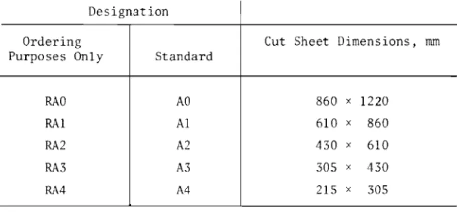
TABLE 4.2 DIMENSIONS OF OVERSIZE SHEETS
Designation Ordering
Purposes Only Standard
RAO AO
RAI Al
RA2 A2
RA3 A3
RA4 A4
Cut Sheet Dimensions, mm
860 x 1220 610 x 860 430 x 610 305 x 430 215 x 305
Note: Until a final decision or standard sheet sizes in Canada is taken by the appropriate CGSB Standard Committee drawing sheets in inch sizes can be used.
4. 1 . 4
Overe i.se Drcaainq Sheets
To provide added protection or to permit edge binding and subsequent print trimming to regular sizes, the over-all paper sizes listed in Table 4.2 are recommended.
4.1.5
Supplementary Size B1
For drawing offices that cannot conveniently accommodate the ISO-AO size drawing sheet, but require a size larger than AI, an intermediate sheet size ISO-Bl
4.2
LAYOUT AND IDENTIPICATION OF DRAWING SHEETS
4.2.1 General:
All drawing sheets require certain basic information, such as title and scale, but
additional information is generally desirable.
The use of preprinted sheets enables
inclusion of information which would be uneconomical if done hy hand.
Sheets may be preprinted for general use or for a particular project.
Every sheet should include the following:
a)
Border lines
b)
Binding margin
c)
Title block
d)
Information panel.
Sheets may also contain:
e)
Sheet grid reference systems
=)
Camera alignment marks for microfilming
g)
Marks to facilitate folding.
4 . 2 . 2
Borders
All drawing sheets should have a border on all four edges, that on the left-hand
side being substantially wider than the others to provide a binding margin.
When borders are not provided, there is a risk of information being lost should the
printing paper slip or be carelessly trimmed, or the print damaged in use.
Recommended
border widths are shown in Table 4.3.
TABLE 4.3
DIMENSIONS OF DRAWING FRA}!E:
WITH BINDING MARGIN
NOIllinal Width of Borders IllIll
Drawing
Dimensions of
Sheet
Size
On Top
Rectangular
Designation
and
On
On
Drawing Frame, mm
Bottom
LHS
RHS
AO
20
40
16
801 x 1133
Al
14
28
12
566 x
801
A2
10
20
8
400 x
566
A3
720
6
283 x
394
A4 720
6
283
x184
NOTE:
Binding margin on A4 sheets
ISon a long edge, on other sheets it is
on a short edge.
4.2.3
Print Trimnr:ng Line
Where ISO-RA series (oversize) drawing sheets are used, a method of indicating the trimming line should be marked on the sheets. This may be by means of broken lines forming a frame, dimensioned to the cut sheet dimensions of regular size sheets specified in Table 4.1, or by other suitable methods of indication.
4.3 MICROfILMING
4.3.1
Relationship of Microfilm and Paper Sizes
The TSO-A series drawing sheets セイ・ particularly well suited to reduction on a 35-mm microfilm. Their aspect ratio is 1:/2 throughout the range; this is also the aspf'ct ratio of the microfilm frame. A selection of print sizes on A series standard
sensitized sheets can be obtained by employing uniformly related reduction and enlargement ratios. For example, a plan produced at 1:100 on an A2 sheet can be reproduced as 1:50 on Al or 1:200 on A3 size.
Where required, camera alignment marks should be provided at the centre of each of the four sides of the drawing sheet. Marks should be in the form of an outline arrowhead pointing outwards and should be placed outside the drawing frame.
4.3.3
Graphic Scale
Drawings prepared for microfilming should contain means of determining the original size. This should be achieved preferably by indicating the drawing frame dimensions. These may be shown outside the drawing frame near a corner. In addition, a graduated line 300 rum long should be shown in a suitable location representing the scale of the drawing for use when a microfilm printout to a different sheet size is required.
4.4 SHEET SIZE DESIGNATION
The sheet size designation number should be indicated on the drawing, preferably in the left-hand bottom corner outside the drawing frame.
4.5 ORIENTATION OF PLANS
A North point should be shown on every location plan, adjacent to the title panel. Whenever practicable all plans for a particular project should be drawn with the same orientation on the drawing sheet.
The North point should preferably face the top of the drawing sheet.
4.6 KEY DIAGRAMS
Where a particular plan occupies more than one sheet, a key diagram may be included to relate graphically the particular block to the over-all design.
This key, with the appropriate part hatched or blacked in, should be located in or adjacent to the information panel on each relevant drawing sheet.
Sheet size Fold lines
Intermediate
Final
I MMMMMセMMMMMMKMMM⦅N⦅セLMMMM⦅N IAO
- - -- -
-> - - - -+ - - - . - - - -... MMMMMセMMMMMtMMM +84,1
X
1189
r-- .t _/\
/\
1)
I , I \ ',,
"
I)
<,
//
/,
,\ / '.' I |セ| ,IV
I I\
/\,
i Ir-,
セ>'
\
II
---...,...--- _.セMM II
A1
AlAi
ャセ セ
I I594
X
841
IeZZMセ
L=
I I - - - --1---1A2
420
X
594
A2
---+---...
420
X
594
//
f\.
)
v
エMMMMMMエMMMMMMMMセMMMMMMM⦅⦅⦅⦅⦅エ⦅MMMMMMMMM⦅⦅K⦅MMM⦅⦅⦅⦅iA3
297
X
420
Sheet size Fold lines
Intermediate
Final
AO
1
x
118
1 I I / I I I 1 1 I+
-J-+-
+ -
-+ - - ,--+ - - -
+---
+
-I I I I I I If
I I I I I 1 r-1 I I 1 I I 0'I
1 I I I N 1 I 1 I I I---+-+--t-- -
+---
-l---t---l---t
I I : I I I I 1 I I 1 I6:
I I I INI
I I I--.1
i
210 I =I
=!
190 II 190 I 190 : 190 I セ セNN ..,...--.,.----...,A1
594
x
841
I'>
I I / / 1 I I / I I I / I I / I I I- -- +- -
-tr -- ; - -- --T---I-i
I I I I 1 1 I I I I I I 1 I I _.--1.セ
=.j.
=.1.
190.L
LセYqLNQ
/\
./'\/-;
\(J;)
1
10 5 r-I I ) I I I' 1 I ( 1セ
I .II I / I I-+-
/ IA2
I , I7
1 IA2
420
x
594
A3
f.:n1
297
x
420
UM-.J
Rセセ
4.7
dセ|wiセgSHEET REFERENCE
Drawings may be classified according to the source of production, e.g.,
architectural, structural, mechanical and electrical.
Drawings within these categories should then be numbered sequentially.
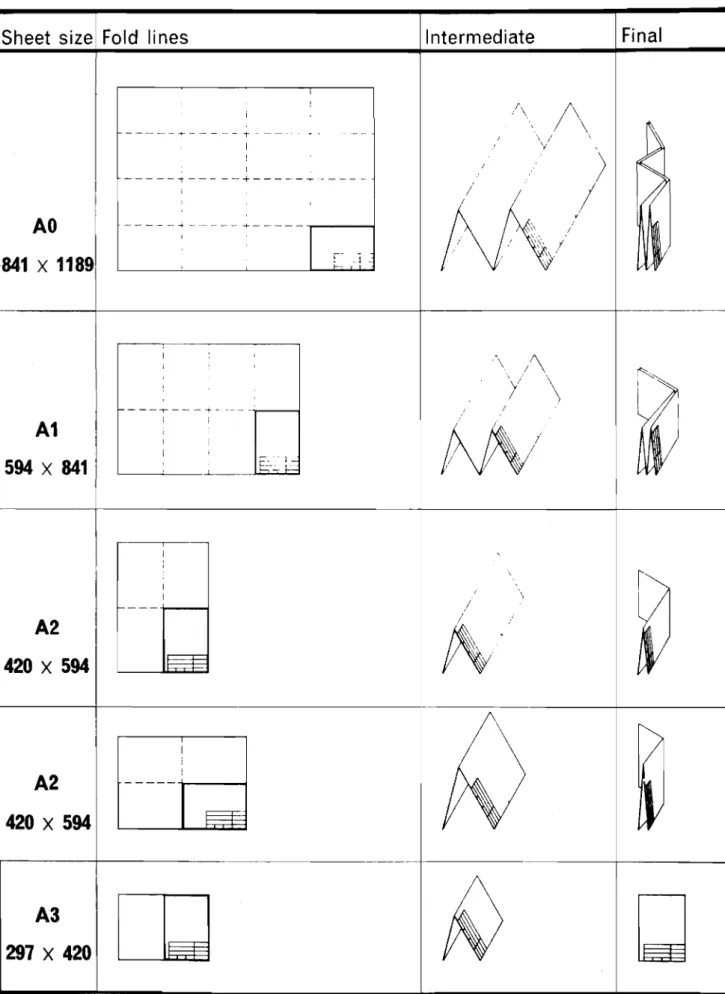
4.8
FOLD LINES
Fold lines should be indicated on drawings irrespective of whether prints are
intended to be folded or rolled for storing.
Hethods of folding are shown in Pigures 4.2
and 4.3.
The number and position of fold lines should be specified by the user, but
generally drawings should be folded to
A4
size.
Drawings preferably should be file
folded.
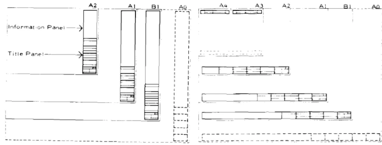
4.9
INl'ORMATTON PANEL
All notes and general information should be located in an information panel.
This
information panel should combine with the title panel to form a block on the drawing
sheet, in a vertical or horizontal arrangement as shown in Figures 4.4 and 4.5.
The panel may contain the following information:
a)
Revision details (each of which is indexed to the revision suffix, dated and
initialled
b)
Notes (general or specific which arc better consolidated under this heading
rather than loosely placed on the drawing)
c)
Key to
ウjセ「ッャウand abbreviations.
(The application of these by rubber stamp or
transfer will save labour and also assist in standardization.)
b- ±='f;e--:::1_
-- . - -- - --- --- --- --- --- --- --- --- _.. _-A4 セ⦅セ⦅⦅ A2. {tᄋᄋZ]sZ]Mセ⦅ti It - T --;-' 'i 81 AD-=-
-r-:'-:'--,-I I, : I I I I I I I I I : I I I I I I II I I' : I , I I I : I I I I I セ iセ , I t----, セMMMi L J I I r-- --, _______セM]MM -i,NNャセ Title p。ョ・ャセMセMM __==i -iャョヲッイュ。エセッョ p。ョ・ャMセ - - - ------ - -- -- - --FIG. 4.4
VERTICAL ARRANGEMENT OF
INFORMATION AND TITLE PANELS
FIG.
4.5
HORIZONTAL ARRANGEMENT OF
INFORMATION AND TITLE PANELS
4.10
TITLE PANEL
To facilitate reference when prints
are simple or file folded, the title panel
should be in either the vertical or
horizontal format, located in the position
shown in Figures 4.4 and 4.5.
It should include the following
information as applicable:
office bureau
a)
Job title (usually made up of nature
of project, name of proprietor and
site address)
consultant expert-conseil
b)
Subject of the drawing
c)
Scale
d) e) f) g) h)Date of drawing
Job number
Drawing number and revision suffix
Drawing reference, where a
classification system has been
adopted
Name of architect (and associated
architect where required) together
with address and telephone number.
seal sceau designed by corcu par drawn by oessoe par approved by approuve par scale echelle revercns revisions detaIl no no, du detail
sheet no. - where detail required no. de la teudle - au detail eXlge sheet no, - where detailed no. de la feuille - ouoetame
date
It may also include names or initials
of the person
(5)drawing or checking the
drawing, and the name of the architect in
charge of the job.
Title panels may be preprinted on the
drawing sheet or on adhesive plastic film
to avoid repetition of work.
Examples of title panels are given in
Figures 4.6 and 4.7.
project projet
drawrng
cessm
project No. du projet sheet No de la feuttle
FIG.
4.6
HORIZONTAL TITLE PANEL
FIG 4.7
VERTICAL TITLE PANEL
Dr..-Ing title" desIgned by dateTitre du dellin ccncu par
drawn by
dessine par
scale: reviewed by
echelle ell.mlne par
date reVl!llons approved by
approuIIl!l par
••
PubliC Works Trav... publiCs project noI
dwO"0 Canada Canada nod\.ic-orer dellSln no4.11
SCALES
4.11.1
standard Scales
The Canadian Government Specifications Board (CGSB) Standard 88-GP-2OM sets out
scales and ratios recommended for use in charts, maps and plans in metric SI.
The
standard includes a comprehensive list ranging from 1:1 000 000 reduction ratio to 100:1
enlargement based on the 1.2.5 series for use in architecture, engineering, construction
and surveying and mapping.
For convenience, the preferred scales for building drawings
are reproduced in Table 4.4.
4.11.2
Choice of Scale
The scale selected for a particular drawing should be determined by consideration of:
a)
The type of information to be communicated;
b)
The need for the drawing to communicate adequately and accurately the
information necessary for the particular work to be carried out;
c)
The need for economy in time and effort in drawing production.
4.11.3
Indication of Scales
The drawing scale should be stated in the title panel of each drawing sheet.
e.g., Scale
1:100
or
Scale:
Not To Scale
HセイイsIセョ・t・
two or more scales are used on the same sheet, the particular scales should be
clearly indicated.
In addition to the statement in the title panel, it may be advisable to indicate the
scale graphically, e.g.,
o
セᆳ
セ20 15 10 5
20
;
40
; 60;80
;FIG. 4.8
GRAPHIC SCALE
4.11.4
Metric Scales (Tnet.rument.e )
The simplicity of the metric system is reflected in the ease with which metric ratios
can be operated (see Figure 4.9).
The decimal subdivision of the scale
1:1
and
1:100
allows for almost all drawings to be done with one metric scaling instrument.
However,
to acquire metric knowledge quickly, it is suggested that the recommended ratios of the
metric scales, as listed in Table 4.4, should be used.
Drawing
TABLE 4.4
Recommended
Scales
PREFERRED SCALES FOR BUILDING DRAWINGS
Use
Former Scales
(Ratios)
Block Plan
1:2000
1:
1000
1:500
To locate the site within the
general district
1"=200'
1"=100'
1"=40'
(1 : 2400)
(1: 1200)
(1 : 480)
Site Plan
Sketch Plans
General
Location
Drawings
1:500
1:200
1:200
1:100
1:50
To locate building work,
including services and site
works, on the site.
To show the over-all design of
the building.
To indicate the juxtaposition
of rooms and spaces, and to
locate the position of
components and assemblies.
1"=40'
(1 :480)
1/16"=1' (1:192)
1/16"=1' (1: 192)
1/8"=1'
(1:96)
1/4"=1'
(1:48)
Special Area
Location
Drawings
1:50
1:20
To show the detailed location
of components and assemblies
in complex areas.
1/4"=1'
1/2"=1'
(1 :48)
(1 : 24)
Construction
Details
1:20
1:10
1:5
1: 1To show the interface of two
or more components or
assemblies for construction
purposes.
1/2"=1'
(1:24)
1"=1'
(1:12)
3"=1'
(1:4)
Full size
(l: 1)Range Drawings
1:100
1:50
1:20
To show in schedule form, the
range of specific components
and assemblies to be used in
the project.
1/8"=1'
1/4"=1'
1/2"=1'
(1: 96)
(1:48)
(1:24)
Component and
Assembly
Details
1:10
1:5
1: 1To show precise information
of components and assemblies
for workshop manufacture.
1"=1'
(1:12)
3"=1'
(1:4)
Full size (1:1)
THIS DRAWING MAY BE USED TO CHECK THE CORRECT INTERPRETATION
OF A SCALE.
tt
this length of scale represents on plan
10 m50 m 100 m 150 m 200 m
1:2000
111I11111I
II
I
I [I
I
I
Njセ
this length of scale represents on plan
1m1
f-
this length of scale represents on plan
10 m10 m 20 m 30 m 40 III 50 m
1:500
11111111111I
I
I
I
*
this length of scale represents on plan
1mセ
セ
this length of scale represents on plan
10 III5 III 10
m
15m
20 III1:200
I
I
I
I
I
I
-W-
this length of scale represents on plan
1mthis length of scale represents on plan
10m
1:100
111111111\11m 2m
3 IIII
I
this length
100mm
4 m 5 m 6 III 7 m 8III 9 m 10III
1
I
I
I
I
I
of scale represents on plan.1
I.
this length of
ウ」。ャ・セ
represents on pl an
1mセ
セ
this length of scale represents on pI an
1m1m 1.5 m 2 m 2.5 m 3 m 3.5 m 4 m
1:50
111111"'11
I
I
I
I
I
I
*
this
1ength of scale represents on plan
100 mm1:20
IE-
this length of scale represents on plan
1m1m 1.5 m 2
m
I
I
I
I
M
this length of scale represents on plan
100 mm0.5 III
0.4 m
0.3
m
Q.2 m
0.1 III
Qf]]]]セセ
this length of scale represents on plan
100mm
1:5
this length of scale represents on plan
1011m
4.12 LINES
4.12.1
General
Lines of differing thicknesses should be used to facilitate the reading of a drawing. The actual thickness of lines used will depend on the purpose of the drawing, its size, scale, whether the lines are in ink or pencil, the proposed method of reproduction and if to be microfilmed. The range of line thicknesses on each drawing should be kept to a minimum and once determined, they should be used consistently for the same type of drawing throughout a project.
4.12.2
Minimum Thickness
The minimum thickness of line to be used is largely dependent on the proposed method of reproduction. The minimum ink line thickness recommended for 1:1 dyeline reproduction is 0.18 mm. ィセ・イ・ drawings are made for reproduction at a reduced scale, either by microfilming or other method, the minimum line thickness used in the original drawing shall be such that in the smallest print to be made, the line will have a thickness of not less than 0.18 mm.
,+.12.3
Range of thicknesses
The recommended range of line thickness for general use is 1.0 mm, 0.7 mm, 0.5 mm, 0.35 mm, 0.25 mm and 0.18 mm. These thicknesses form a series which follows a
/2
progression in accordance with the sizes of drawing sheets given in clause 4.1 of this Manual. One great advantage in the use of this series is that when drawings are
microfilmed and re-enlarged to a different scale, using standard reduction and enlargement ratios, the resulting line thicknesses are still standard and any necessary modification can be made using standard drawing pens and lettering stencils.
4.12.4
Thickness Grouping
It is not necessary, or desirable, that all of the line thicknesses given in clause 4.12.3 be used together. For anyone drawing it is recommended that lines from only one of the groups given in Table 4.5 be adopted. For general office use Group C is
recommended.
TABLE 4.5 LINE THICKNESS GROUPINGS, mm
Size
A
B
CD
Thick 1.0 0.7 0.5 0.35
Medium 0.7 0.5 0.35 0.25
Thin 0.5 0.35 0.25 0.18
4.12.5
Thicknesses
for Specific Purposes
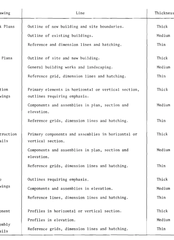
A guide to the relative thicknesses of lines for specific purposes is given in Table 4.6.
Drawing
TABLE 4.6
LINES FOR SPECIFIC PURPOSES
Line
Thickness
Block Plans
Site Plans
Location
Drawings
Construction
Details
Range
Drawings
Component
and
Assembly
Details
Outline of new building and site boundaries.
Outline of existing buildings.
Reference and dimension lines and hatching.
Outline of site and new building.
General building works and landscaping.
Reference grid, dimension lines and hatching.
Primary elements in horizontal or vertical section,
outlines requiring emphasis.
Components and assemblies in plan, section and
elevation.
Reference grids, dimension lines and hatching.
Primary components and assemblies in horizontal or
vertical section.
Components and assemblies in plan, section and
elevation.
Reference grids, dimension lines and hatching.
Outlines requiring emphasis.
Components and assemblies in elevation.
Reference lines, dimension lines and hatching.
Profiles in horizontal or vertical section.
Profiles in elevation.
Reference grids, dimension lines and hatching.
Thick
Medium
Thin
Thick
Medium
Thin
Thick
Medium
Thin
Thick
Medium
Thin
Thick
Medium
Thin
Thick
Medium
Thin
4.13
LETTERING AND NOTES
4.13.1
General
Lettering should be used on drawings to convey information that is not readily or
clearly indicated by graphics alone, and the combination of lettering and graphics should
fully and concisely define the object being drawn.
The most important requirements for lettering are legibility, reproducibility and
ease of execution.
These are particularly important due to the increased use of
microfilming which requires optimum clarity and adequate size of all details and
lettering.
It is recommended that all drawings be made to conform to these requirements,
and that particular attention be paid to the avoidance of the following common faults:
a)
Unnecessary fine detail,
b)
Poor spacing of details,
c)
Carelessly drawn figures and letters,
d)
Inconsistent delineation,
e)
Incomplete erasures, leaving ghosted images,
f)
Use of differing densities, such as pencil, ink and typescript on the same
drawing,
g)
Use of heavy guidelines for lettering.
4.13.2
Notes on Drawings
In placing notes on drawings the following principles should be applied:
a)
Generalized notes, i.e., those that apply to the drawings as a whole or involve
similar parts of detail over the body of the drawing, should be consolidated in
a prominent position on the sheet or, preferably, in the notes column of the
information panel and referred to if necessary by a notation adjacent to the
detail, e.g., Note 1, Notes 1 and 2, etc.
b)
Special notes should be placed clear of, but as close as practicable to, the
items to which they refer.
In no case should lettering obscure any part of the
drawing.
c)
Leaders linking notes with details should be used only where confusion might
otherwise arise.
d)
The underlining of lettering or notes is not recommended.
If special attention
is required to be drawn to a note, the word "Important" or "Note" should prefix
the lettering.
e)
Lettering, when not written to be viewed from the bottom of the sheet, should be
placed for viewing from the right-hand side of the sheet.
4.13.3
Lettering
The requirements and principles listed in clauses 4.13.1 and 4.13.2 are best met by
the style of lettering known as standard upper case roman (simple block without serif or
scroll) which should be used exclusively, except for metric symbols requiring lower case
letters, e.g., millimetres (mm) and centimetres (cm).
Condensed or extended styles are
not recommended.
Decimal points should be heavier than the lettering and should be shown on the lower
line, e.g., 53.4 kg.
4.13.4
Size of Lettering
The line thickness for letters and figures should be in the same range as the line
thicknesses used on the particular drawing, as described in clause 4.17..2.
These bear
the same
12
relationship to one another as do paper sizes.
It is expected that pens in
the full range of sizes recommended will be available commercially.
The height of lettering should be in accordance with Table 4.7 consistent with line
thickness used.
TABLE 4.7
recohセiendedHE ICHT OF LETTER INC
Height of Letters, mm
Thickness of
Lines, mm
0.18
0.25
0.35
0.5
0.7
1.0For Contact
Printing
(Ratio 1:10)
1.82.5
3.5
5.0
7.0
10.0
For Hicrofilming
(Ratio 1:14)
2.5
3.5
5.0
7.0
10.0
14.0
For microfilming, letters and figures should be drawn so that in the smallest print
to be made from the film, they will have a height of not less than 1.3 mm.
The use of the recommended line thickness of 0.25 mm for lettering on the Al sheet,
using a thickness/height ratio of 1:10 (and therefore a height of 2.5 mm) will, when
reduced to A2, give a height of 1.8 mm and when reduced to A3 a height of 1.3 mm, which
is still legible to most people.
Further reduction to 0.9 mm is not advisable.
Where microfilming, rather than contact printing, is the major consideration, a
thickness/height ratio of 1:14 is recommended.
Fine lines and miniature lettering should not be used because they are unsuitable for
reproduction either by contact printing or microfilming.
The size of the figures denoting the project and drawing numbers should be not less
than 7 mm high, so that
the microfilm will be readily identifiable at low magnitudes.
Symbols, such as signs for power outlets and telephones, should be at least as large
as the lettering.
4.13.5
Spacing
There should be adequate and even spacing between letters and adequate space inside enclosed letters such as P and R. Words should be compact without being cramped and close enough to one another to allow sentences to be easily read.
The clear space between letters and figures should be not less than double the thickness of the line used. The space between words should be equal to that required by the letter
a
if touching both words and the space between sentences should be double that between words.Spacing between lines of lettering should be not less than one half the height of the characters.
4.13.6
Typewriting
Where variable typeface typewriters are used, the previously recommended
relationships between height and thickness of letters should be maintained, particularly if reduction of the drawing is planned.
Where typewriting is used, the type face, size and density should be selected or controlled to conform as nearly as possible with the line work previously recommended and to that used on the drawing. A typeface without serifs is preferred.
4.14
SYMBOLS
Pl.AN & SECTION
c=J
.セB _.."..',',..
.... ,
- ' ."-,': - . -..
.: ..•.• >••
ASSEMBLY DRAWINGS SCALE 1 10 OR LARGER MMMGセMGMGMGMGMMNM ELEVATIONI
I セZ- - - - 1
SPACING TO REPRESENT COURSING
+
GENERAL LOCATION DRAWINGS
SCALE 1·50 OR SMALLER
PLAN & SECTION
MATERIALS
CUT 510NE MASONRY BRICK MASONRY
ARTIFIC IAL STONE MASONRY
LINE SPACING TWICE AS WIDE
___セヲorXrick THAT fOR CUT STONESTIPl'LE DENSITY ONE-HALF OF
TOO FINE TO HATCH
MARBLE
CONCRETE <tp.O.. . •セN 4
····1
- - ; - ' ,
STIPPLE DENSITY ONE-THIRD
__ OF THAT FORCUT..illNE _
Q
OQセ j
' '0 セ "',: セェjNB :MLMセ v., . N⦅セ⦅•••
セ
•..
REINFORCED CONCRETES1IPPLE OEHSITY ONE-THIRD
__ AヲtイiセュrNN」uQstone
QNᄋGᄋᄋNGᄋᄋᄋセᄋᄋ ᄋᄋᄋNᄋセNᄋᄋャᄋᄋᄋM
. Yセ . '
,.p
-'
....
'. . .CONCRETE OR CINDER BLOCK
LINE SPACING THREE TIMES AS'II1IJE alfoセjャNrャck
---,
I - - - j
MMMMMセ
SPACING TO REPRESENT COURSING
CERAMIC TILE TOO ANE TO HATCH
I - GセBBBGMQ l
TERRAZZO
GLASS
WllOO FRAMI NG
WOOD (FINISHED I
RIGID INSULATION
GENERAL LOCATION ORAWINGS
SCALE1SO OR SMALLER
PLAN & SECTION
TOO fiNE TO HATCH
+
fOR NEW WORK+
fOR ALT£RATION WORKTOO FINE TO HATCH
+
ELEVATION
SHOW PA1TERN Of STRIPS
セMM
:GL
INCLUDE GL WHERE REOUIREO FOR CLARITY
ASSEMBLV ORAWINGS
SCAli ',10 OR LAR6ER__ _ _
PLAN & SECTION
r '
-*9
f l , ",,,,,,,,··,'•.,.'.,,·,,···,, J,'.',! i " ,/ i " / .,' ..' I /// BATT INSULATION 1--- ,-, ---- - - + - - - -I> ",_ (.' (I
,) r(,ll," ",:, ,
n\: \\ \
L7
- - - + - - - 1 STRUCTURAL STEELBRONZE. BRASS. COPPER. &ASSOCIATED ALlDYS
I
[
L
.LiMMMMMMMMMMMMMセ
-AS FOR STRUCTURAL STEEL
セセ
N BLゥLG LWLG O G
,./d /" f"
; I
-1 - - - > . - - - t - - - j
ALUMINUM AS fOR STRUCTURAL STEEL
I
---i
I
GRAVEL FILL
CINDER OR SLAG FILL
FIRE BRICK
PLYWOOD
GLASS BLOCK I I
it
NATURAL STONE
-RIP RAP, FIELD STONE, ETC.
+
II Ii+
SAND, FILL. PLASTER,
GYPSUM BOARD & CEMENT
t
f
WALLS
WAll MATERIAL SYMBOLS ARE SHOWN lilLY WHERE MATERIAL OR lIINSTRUCTION CHANGES OR TERM INATES
WALL MATERIAL SYMBOLS NEED NOT BE USED WHEN WALL CONSTRUCTION DETAILS ARE SHOWN IN A WALL TYPE SCHEDULE
ESPECIAllY APll.ICABlE TO SMAllscm ORAWING
NOTE, IN RENOVATION WORK MATERIAL SYMBOLS ARE NOT USED FOR EXISTING WALLS; MATERIAL SYMBOLS ARE USED ONLY TO DIFFERENTIATE NEW WORK FROM EXISTING; WALLS OR PARTITIONS TO BE REMOVED ARE SHOWN BY BROKEN LINES
WALL OF SHEET GLASS OR OTHER TRANSPARENT OR TRAtjSLlICENT SHEETS IN WOOD OR METAL FRAME; E.G STORE WINDOW
WALL OF GLASS BLOCK OR OTHER TRANSPARENT OR TRANSLUCENT MASONRY
I I I
Itt
A WINDOW BUILT INTO A TRANSPARENT OR TRANSLUCENT MASONRY WALL
i i
31
IIOi
I I I I I It
PANEL TYPE CURTAIN WALL, WITHOUT WINDOWS
PANEL TYPE CURTAIN WALL. WITH WINDOWS
PARTITION S
FRAME PARTITION
IN NEW WORK MATERIAL SYMBOLS ARE NOT SHOWN 1flNISHEO BOTH SlOES FINISHEO ONE SlOE ONLY
GLAZED PARTITION - ANY TRANSPARENT OR TRANSLUCENT SHEET MATERIAL, EITHER FLAT. CORRUGATED, OR TEXTURED IN ANY WAY
TOILET PARTITIONS
THE SAME PARTITION SYMBOL IS TO BE USEO FOR All TYPES OF TOIlET PARTITION CONSTRUCTION AT SCAlES Of1,50 &1,100
MOVABLE PARTITIONS
WITH OOORS
+
SOllO+
+
+
-
- ..iUlr1.J-WITHOUT OOORS WITH CURTAIN セ
t=+
GLAZEOKセ
WIRE PARTITION S ---x---': - - - ' X - - - '
,.---X---TWO - TRACK ACCOROID N PARTITIONS
MMセ
\ill",OOORS INllACKEO POSITION
III \
III
_---=
' J - - - = _L .-::::::
OOORS ARE HUNG ON TWO TRACKS AND STACK WHEN OPfN; PILOT OR PASS OOORS ARE SHOWN IN USUAL WAY
+
セ セi セ]]セi セ
i
OPENING EXTENOS UP TO A LINTEL, ARCH OR VALENCE
ARCHWAY - AN OPENING IN AWALL OR PARTITION, WITHOUT DOORS
DOORS
SINGLE SWING DOORS
NOTE SIZE AND TYPE Of ODOR IS SHOWN WHEN A DOOR SCHEDULE IS NOT USED
II
USE ONLY If SPACE AND CLARITY DICTATE
II
" WITH SIDElIGHT DOUBLE ODORS WITH THRESHOLDI i i
•DUTCH ODOR, IN TwtJ SECTIONS, \11TH UPPER AND LOWER LEAVESDOUBLE ACTING DOORS
IN·AND - OUT DOORS
FOLDING DOORS
CENTRED ON TRACK
--N'
TO ONE SIDE Of. RACKACCORDIO N DOORS
t
WITHOUT POCKET WITH POCKET
SLIDING DOORS
t
DOOR SLI DES INTO POO ET SURFACEセmounteo ODOR SLIDING EXPOSED ON FACE OF WALL
TWO ODORS SLIDING U ONE WAY ON THE FACE, LEAV',NG mAR OPENING
BYPASSING SLIDING ODORS BOTH MOVING TO EI1HER SIDE BUT NOT ,EAVING CLEAR OPENING
ROLL- UP DOORS
I AREA octUPIEO BY DOOR HOUSING
PlAN SECTION
AREA Of DOOR IN OPEN POSITION
OVERHEAD DOORS
PLAN ⦅セャャNNNM SECTION
VERTICAL LIFT ODORS
Oセ]]]
PLAN , , , I I , ,I I ' I I 1 ' 1 I . 1 .1 SECTION
JJL
REVOLVING DOORS \\ \\+
/ v / Iセ
セ
..WINDOWS
IN PLAN, FOR ALL TYPES OF SASH
fLUSH SILL MULLIONS fLUSH WITH WALL ON INSIDE
SLIP SILL WITH MULLIONS & CONTINUOUS STOOL
LUG SILL WITH MULLIONS Of TYPICAL WALL CONSTRUCTIOI
IN ELEVATION
SYMBOLS APPLY REGARDLESS Of MATERiAl USED IN MANUfACTURE Of SASH.
DOUBLE HUNG
/
1\
\1/
\
1\ / \/
\1/
CASEMENT/\
I \/
'/
\
I \ //
TOP HINGED PROlE ClEOLEFT SIDE HINGED
BOTTOM HINGED
I
Q
.> <, - -"<,...- , / ' / I PIYOTTEORIGHT SIDE HINGED