HAL Id: hal-02515658
https://hal.archives-ouvertes.fr/hal-02515658
Submitted on 23 Mar 2020HAL is a multi-disciplinary open access archive for the deposit and dissemination of sci-entific research documents, whether they are pub-lished or not. The documents may come from teaching and research institutions in France or abroad, or from public or private research centers.
L’archive ouverte pluridisciplinaire HAL, est destinée au dépôt et à la diffusion de documents scientifiques de niveau recherche, publiés ou non, émanant des établissements d’enseignement et de recherche français ou étrangers, des laboratoires publics ou privés.
Power supplies for excilamps -a review of structures for
UV emission control
Dimitri Schitz, Hubert Piquet, Rafael Diez, Mahamat Abakar Djibrillah,
Sounil Bhosle, Victor Tarasenko, Eduard Sosnin
To cite this version:
Dimitri Schitz, Hubert Piquet, Rafael Diez, Mahamat Abakar Djibrillah, Sounil Bhosle, et al.. Power supplies for excilamps -a review of structures for UV emission control. 12th International Symposium On Science and Technology of Light Sources, Jul 2010, Eindhoven, Netherlands. �hal-02515658�
Power supplies for excilamps – a review of structures for UV emission control
D.V. Schitz
1, H. Piquet
2, R. Diez
3, M. Djibrillah
2, S. Bhosle
2, V. Tarasenko
1, E. Sosnin
1 1Institute of High Current Electronics SB RAS, Akademichesky Ave. 2/3, Tomsk, 634055, Russia,
2
LAPLACE Laboratory, UMR CNRS-INPT-UPS, Toulouse University, 2 rue Camichel, 31071 Toulouse, France
3
Electronics Department, Pontificia Universidad Javeriana, Bogotá, Colombia Contacts:Hubert.Piquet@laplace.univ-tlse.fr –schutz@loi.hcei.tsc.ru ABSTRACT
Dielectric barrier discharge excimer lamps (excilamps) are well known powerful and efficient sources of UV emission. The UV emission is tightly related to the electric power transferred to the lamp and very different performances are obtained, depending upon the characteristics of the power supply which is used. This paper proposes a review of power topologies, which have been used by the authors for various purposes (laboratory physic domain investigations and UV emission process oriented studies). For each of them, the topology and its operating principle, as well as a discussion of the merits concerning the performances (UV emission, design pitfalls, efficiency, reliability, waveforms …) are proposed.
POWER SUPPLY REQUIREMENTS FOR DBD EXCILAMPS
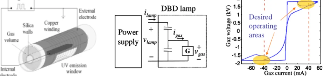
The design of power supplies for DBD excilamp [1] relies on their electrical characteristics, described by the equivalent circuit [2] and the static electrical characteristic of the gas which fills the bulb – see Fig. 1. To establish a power transfer to the lamp, a high voltage (Vthreshold # 5kV) has to be applied across its terminals.
Power supply ilamp + _ G DBD lamp + _ vlamp igas vgas Power supply ilamp + _ G DBD lamp + _ vlamp igas vgas Desired operating areas Ga z vo lt age (kV ) 0 0.5 1 1.5 2 -0.5 -1 -1.5 -2
Gaz current (mA)
0 20 40 60 -20 -40 -60 Desired operating areas Ga z vo lt age (kV ) 0 0.5 1 1.5 2 -0.5 -1 -1.5 -2 0 0.5 1 1.5 2 -0.5 -1 -1.5 -2
Gaz current (mA)-20 0 20 40 60 -40
-60 -40 -20 0 20 40 60
-60
Fig. 1 DBD excilamp (a) - equivalent circuit (b) - electrical characteristic of the gas (c)
Once the breakdown is reached, according to the capacitive nature of the lamp, a bidirectional lamp current is needed (frequency range 20 kHz – 150 kHz). UV emission being tightly correlated with current, power or current control of the electric generator is a desirable feature; the studied power range is from 50W up to several 100W. The high voltage needed across the lamp requires the installation of a step-up transformer between the power stage and the bulb. The transformer, according to the frequency range, uses ferrite cores. The high voltage on the secondary implies a large turn number and careful insulation (Teflon interlayer). SINE VOLTAGE POWER SUPPLY
Physicists frequently use sine high voltage for excilamp excitation [2][3] in investigations. Usually such supplies have 2 main parts: a power amplifier and a step-up transformer, which may be assembled as a self-excited oscillator: the inductance of the transformer and the added capacitor define the oscillating frequency.
Fig. 2 Resonant power supplies: linear audio amplifiers (a) and the half-bridge converter (b)
For basic realizations, radio valves or integrated audio amplifiers (for instance TDA7294 [5]) can be used, as on Fig. 2(a). TDA7294 have short circuit protection and thermal shutdown, making this resonant supply very failsafe. The main drawback is its poor efficiency, due to linear operation of the amplifiers, but regarding the power level (typ. 150W) and the application (lab. investigations on plasmas), this issue is not critical. A 6.5 kV magnitude sine waveform is obtained on the secondary of the ferrite core transformer.
For applications where efficiency is important, static converters using power transistors (MOSFET, IGBT) in switched mode (see Fig. 2(b)) are used: rectified AC network voltage supplies a half or full bridge topology; the switching legs associate two MOSFETs with anti-parallel diodes. The obtained square voltage excites the resonant circuit: a ferrite core choke L and a capacitor C associated with a transformer T. Therefore a high voltage of sine shape (amplitude 3-6 kV) is obtained on the secondary of T. The magnitude of the output voltage is adjusted by means of the driving frequency, relatively to the eigen frequency of the resonant loop L-C-T [4]. This simple supply is failsafe: output overload only leads to quenching of resonance oscillations, but primary current remains controlled. Over voltages and voltage spikes arising in the step-up transformer (due to sparks, bad contacts …) that could damage the supply are filtered by the LC circuit; anti-parallel diodes cut-off over-voltage. Thanks to zero current switching of transistors (ZCS) [4], efficiency is improved. PULSE POWER SUPPLIES
Efficiency increase of DBD excimer lamps [6][7][8] at high-voltage short pulse excitation and several tens of kHz has been established with a diffuse discharge (great number of cone-like micro-discharges). Bridge circuits Fig. 3(a) are widely used for high voltage pulsed power (application range 20-300W, up to 1kW): rectified AC network voltage (eventually with power factor correction - PFC) feeds a half or full-bridge converter. Each switching leg has two MOSFETs or IGBTs with anti-parallel diodes, controlled by a pulse-width modulator (PWM). High-voltage pulses with 20-150 kHz frequency are produced at the secondary of the transformer (its primary winding, connected to the bridge, uses RF cable because current slope belongs to MHz range). The voltage applied to the bulb causes spike currents, giving very efficient UV emission spikes. Current controlled topologies [9] use thyristor-like synthesized semiconductors. Operating in discontinuous mode (resonance between L and the lamp) - Fig. 3(b), they offer direct and instantaneous lamp current control; this has proven to efficiently handle UV emissions. Continuous mode topologies are also considered.
* S1 S1’ 1 * La mp La mp 1 : n : E * S0 L * * S1 S1’ 1 * * La mp La mp 1 : n : E * * S0 L
Fig. 3 Pulsed power supply: (a) voltage source – (b) current source
Acknowledgement: part of this work is French-Colombian cooperation, supported by ECOS-Nord / COLCENCIAS / ICETEX program.
REFERENCES
[1] M.I. Lomaev, E.A. Sosnin, V.F. Tarasenko, D.V. Schits, V.S. Skakun, M.V. Erofeev, A.A. Lisenko.
Capacitive and Barrier Discharge Excilamps and Their Applications (Review). Instruments and
Experimental Techniques, 2006, Vol. 49, No. 5, pp. 595-616
[2] R. Diez; JP. Salanne; H. Piquet; S. Bhosle; G. Zissis: Predictive model of a DBD lamp for power supply
design and method for the automatic identification of its parameters – E.P.J. App. physics, 2007.
[3] Kogelschatz U. Silent discharges for the generation of ultraviolet and vacuum ultraviolet excimer
radiation // Pure &App/. Chem., Vol. 62, No. 9, pp. 1667-1674,1990.
[4] Y. Cheron, Soft commutation, Chapman and Hall, 1992
[5] STMicroelectronics, TDA7294, Application note. http://www.st.com
[6] Mildren R.P., Carman R.J. Enhanced performance of a dielectric barrier discharge lamp using
short-pulsed excitation // J. App. Physics D. – 2001. – 34. – L1-L6.
[7] Vollkommer F., Hitzshke L. Dielectric Barrier Discharge // Proc. of the 8th International Symposium on Science and Technology of Light Sources (Greifswald, Germany, 1998), pp. 51–60.
[8] Lomaev M.I., Schitz D.V., Skakun V.S., Tarasenko V.F. Influence of excitation pulse form on barrier
discharge excilamps efficiency // Proc. of SPIE. – 2002. – V.4460. – P.38-45.
[9] R. Diez; Hubert Piquet; Sounil Bhosle : Control of UV Emission of an Excimer Lamp by Means of a