HAL Id: hal-03097697
https://hal.archives-ouvertes.fr/hal-03097697
Submitted on 5 Jan 2021
HAL is a multi-disciplinary open access
archive for the deposit and dissemination of
sci-entific research documents, whether they are
pub-lished or not. The documents may come from
teaching and research institutions in France or
L’archive ouverte pluridisciplinaire HAL, est
destinée au dépôt et à la diffusion de documents
scientifiques de niveau recherche, publiés ou non,
émanant des établissements d’enseignement et de
recherche français ou étrangers, des laboratoires
Event-B formalization of a variability-aware component
model patterns framework
Jean-Paul Bodeveix, Arnaud Dieumegard, M Filali
To cite this version:
Jean-Paul Bodeveix, Arnaud Dieumegard, M Filali. Event-B formalization of a variability-aware
component model patterns framework.
Science of Computer Programming, Elsevier, 2020, 199,
Event-B formalization of a variability-aware component model patterns
framework
1Jean-Paul Bodeveixb,a, Arnaud Dieumegardc,d, Mamoun Filalib,e
aUPS - 118 Route de Narbonne, F-31062 Toulouse bIRIT - 118 Route de Narbonne, F-31062 Toulouse cONERA, 2 Avenue Edouard Belin, F-31055 Toulouse dIRT Saint Exupéry, 3 Rue Tarfaya, F-31400 Toulouse eCNRS - 118 Route de Narbonne, F-31062 Toulouse
Abstract
In the domain of model-driven engineering, patterns have emerged as a ubiquitous structuring mechanism. Patterns are used for instance at the requirement analysis level, during system design, and during the deployment and code generation phases.
We focus on formalizing the operational semantics of pattern application on component-based system designs. More precisely, our ultimate goal is to provide a semantic framework to support the use of patterns for the production of correct-by-construction architectures, i.e., the structural (static) correctness of the architectures obtained through the formal application of patterns. To that end, we propose an Event-B framework for patterns specification, instantiation and application. This model is built incrementally through horizontal refinements which introduce components, ports, and connectors. Patterns with variability are defined, instantiated and can be applied to user models. We show that these operations preserve the structural properties of hierarchical component models.
Keywords: Design patterns, formal refinement, variability, system engineering, critical systems
1. Introduction
In the domain of model-driven engineering, patterns have emerged as an ubiquitous structuring mechanism. Pat-terns are used for instance to express and structure requirements and to ease their analysis [Car15]. During the process of system development, during deployment, or for code generation activities, they ensure knowledge capitalization, and production homogeneity. Patterns may take various forms and are specifically structured: textual patterns expressed as sentences, structural patterns for describing components combinations, code patterns for code generation.
The work we present here results from exchanges with safety system engineers who practice patterns for solving identified safety issues. Their application of patterns produce refined system architectures taking into account safety-specific concerns. In this context, we focus on automatically instantiated safety refinement patterns. The patterns we rely on are based on the ones detailed in [PKK15].
We are interested in making the use of such a notion in the system development process precise. Our ultimate goal is to build environments that support correct-by-construction component-based architecture transformations, i.e., the structural correctness of the architectures obtained through the application of patterns. For this purpose, we show that the transformed model satisfies well-formedness properties such as: component inclusion relation is acyclic, links be-tween two components do not cross other components boundaries, modelling elements of the transformed architecture model only come from source models and pattern models. For this purpose, we propose to use Event-B as the support
1This work was initiated while working on the MOISE project at IRT Saint Exupery then continued with the support of ONERA
Email addresses: [email protected](Jean-Paul Bodeveix), [email protected] (Arnaud Dieumegard),
platform to define the notion of hierarchical component. This Event-B model is built incrementally through horizon-tal refinements which introduce components, ports and connectors. Next, refinement defines patterns variability and their instantiation by fixing variable elements. Last, we define pattern application on user models. We show that this transformation preserves the structural properties of the component model. We remark that Event-B is mainly used to assess the correctness of pattern instantiation and application.
Achieving the production of structurally correct component models may be reached using different approaches. The translation validation approach [PSS98] consists in verifying each individual translation, whereas transformation
verification[BL09] consists in verifying the generator itself once and for all. In this paper, we adopt the transformation
verification approach. The specification of the transformation and its verification are done incrementally through successive refinements, as supported by the Event-B method [Abr10].
Section 2 motivates our proposal by means of a small case study, and presents our pattern model. In Section 3, we describe how patterns are applied to component models. Section 4 briefly presents Event-B and its set-based notations. Section 5 introduces our formal modeling framework based on Event-B. Section 6 details within this formal setting the steps followed to apply a pattern to a model. Section 7 provides insights on our prototype tool. Section 8 discusses some related work. Section 9 concludes and suggests some future work.
This paper is an extension of work originally presented at the FACS 2018 conference. Compared with [BDF18a], • New examples of component-related pattern application (voter, recovery block pattern) and link-related patterns
(monitor-actuator) are provided.
• The proof of the preservation of the acyclicity of the sub-component relation by pattern application is detailed. Also, a variant expression justifies the termination of sub-component unfolding.
• The prototype Caml tool is presented together with raw text-based encoding of models as processed by the tool. • We provide the component/pattern metamodel on which our Sirius [VMP14] editor is based.
2. Motivating example
We describe here an example that will be used first to clarify what we mean by a pattern and by pattern application. Section 2.1 features a very simple component model. We then showcase the transformation of this model to replicate one of its components. Focus will be on the N-Version programming pattern as described in [Arm10] or [PKK15]. This pattern is proposed in the context of architecture safety to enhance system robustness. We detail its structure and content, the solution that is provided by the application of such a pattern, and its complexity from the scope of its variability.
2.1. Component models
In our work, we consider hierarchical component models as an abstraction of the classical “boxes and arrows” mod-eling formalism used to model: systems as for example Capella [SVV+16], SysML [OMG12] or AADL [FG12]; soft-ware as for example BIP [BBB+11], UML [RJB04], Scade [ADS+06]; or hardware as for example VHDL [HGW00]. In each of these formalisms, components are connected through arrows (and sometimes ports or interfaces).
We provide in Fig. 1 an example of a very simple component model. This model features the sc1 component with two input ports and one output port connected to sc2 through the link l3. In addition to the structural description of our simple model, we have attached to the sc1 component one comment (square box) representing the association of a component with its specification, its verification or its validation artifacts or any other information of interest related to the component.
2.2. Replicating a component
In the use case depicted in this paper, we propose to take the example that some analysis of the system leads to the need to provide different implementations of the sc1 component to make the system fault tolerant. This mechanism is in this context referred to as a replication of a component.
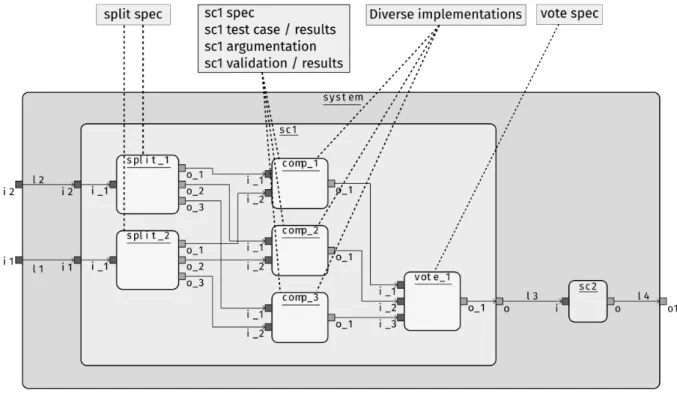
An example of our simple system where the sc1 component has been replicated is provided in Fig. 2. In this new version of the model, we have three versions (comp_X) (𝑋 ∈ {1, 2, 3}) whose inputs are taken from the original
Figure 1: A simple component model
inputs of the sc1 component and dispatched using specific duplication (split_Y) (𝑌 ∈ {1, 2}) components whose purpose is to replicate their inputs on each one of their outputs (the specification of these components is provided in the split speccomments). Then, the outputs of the replicated comp_X components are connected to a new component (vote_1) in charge of taking the decision of which one of the comp_X component output shall be relied on and sent to the outputs of the original sc1 component.
Figure 2: A component model where a component is replicated three times
One may remark that applying such a replication not only preserves the original structure of the model (the interface of the sc1 component is the same), but also duplicates elements of the original model (the new comp_X components) and introduces new elements such as replication constraints (Diverse implementation of comp_1, comp_2, comp_3), and component specifications (vote spec, and split spec).
2.3. Implementing a link
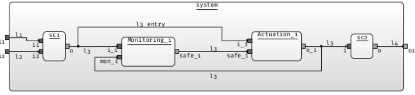
We complement the previous example with an example where the analysis of the system leads to the need to make more safe a link between components. In this context we provide a possible solution in the shape of additional
components implementing monitoring on the link between components sc1 and sc2. Figure 3 provides an example of such an implementation of a link. The idea here is to replace the link with two components (Monitoring_1 and Actuation_1) implementing the monitoring of the value carried by the link and the modification of the value carried by the link to a failsafe value when monitoring detects a problem on the value.
Figure 3: A component model where a link has been implemented
Once again, implementing a link this way preserves the original structure of the model and integrates additional elements in the model (new components and specification information).
2.4. Pattern model
The previously depicted model transformations are considered in our setting as an example of the application of a design pattern. The model of Fig. 1 is the source model, and the model of Fig. 2 is the target or destination model where the pattern has been applied. What remains to be defined is what is the model of the pattern itself.
Many design pattern description formats have been defined in the literature. We decided to rely on the classical pattern description format proposed by Coplien [Cop96]. This comprises many information among which are the name of the pattern, its context of use and the problem solved by the pattern, the strength and weaknesses of the pattern, a graphical model representation and much additional information. We also rely on the work of Preschern et al. [PKK15] where a set of architectural safety patterns are proposed for high level architecture definition. These patterns are connected to IEC 61508 standard methods for achieving safety and are extended with formal argumentation models. An example of such a pattern is provided in Fig. 4.
While this representation of a pattern is very interesting, it is nevertheless restricted to its structural description. It may be interesting to explicitly express the parameters of the pattern and its variability. In the context of the N-Version Programmingpattern, 𝑁 is a parameter meaning the number of times the software is developed. This parameter also impacts the implementation of the voting algorithm (vote block). In addition to these, the links between the blocks described in the Solution section of Fig. 4 are a simplification of the actual possible links between blocks as there may be multiple links between these blocks: the 𝑁 versions of the block all have the same number of inputs and outputs. Both of these numbers are also parameters of the pattern that shall be made explicit. We thus propose an extension of this model representation of patterns where these parameters are made explicit.
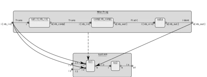
Fig. 5 is our proposal for an alternative graphical representation of the N-Version programming pattern model. In this model, we rely on structural elements like components, ports, and links between components through ports, and multiplicityobjects attached to components and ports. multiplicity markers are attached to components and ports. They appear inside brackets in the figure. In this pattern model, four different multiplicity elements are defined: nb_comp, nb_in, nb_out, and nb_vin. They respectively stand for the number of times the component is replicated, the number of input and output ports of the replicated component, and the number of inputs of the vote component.
Figure 5: The N-Version programming pattern model
By selecting the model element to be replicated (sc1 in Fig. 1), the multiplicity markers nb_in and nb_out are set respectively to two and one. The user shall then provide the value for nb_comp which is set to 3 in this case. Based on the user selection and provided values, the pattern model is instantiated: 1) its root component will have two input ports and one output port; 2) the root component of the pattern will be renamed as sc1; 3) the comp component will be replicated nb_comp times as copies of the sc1 component with nb_in input ports and nb_out output ports; 4) the split component will be instantiated nb_in times with one input port and nb_comp output ports; 5) the votecomponent will be instantiated with nb_comp input ports and nb_out output ports (here one); 6) links between components are elaborated depending on their connection pattern (detailed in the following section); Here, we use the
Transposepattern (written Trans in figures) to connect port 𝑖 of component 𝑗 to port 𝑗 of component 𝑖; in the same
way, the FlatC pattern connects all the ports of comp replicates to distinct ports of the vote component: nb_vin is constrained to be nb_comp×nb_out. 7) finally, the original sc1 model element is replaced with the newly produced sc1component and its content. Fig. 6 shows two instances of our N-Version-Programming pattern, the first one with nb_in=2, nb_out=1, nb_comp=3 and the second one with nb_in=2, nb_out=2, nb_comp=3.
Fig. 8 is our proposal for an alternative graphical representation of the Monitor/Actuator pattern model provided in Fig.7 which introduces a monitor to check the result computed by the main component and sends it a shutdown signal
(a) (b)
in case an error is detected. This model of the pattern is simpler than the previous one as only Identity links (Ident in the figure) are used to connect a single port of a single source and a single target component and all multiplies have have the default value (1).
Figure 7: Monitor actuator pattern extract from [PKK15]
Figure 8: The Monitor-Actuator pattern model
In our setting, a pattern model is thus a family (in the product line [KCH+90] terminology) of models. Each combination of multiplicities allows for the definition of a pattern instance. The production of design pattern instances and the application of the produced pattern instance on a model element shall thus be implemented for components and links.
The purpose of the Event-B model proposed in this paper is first to formally define the previously presented struc-ture of a pattern, and second to propose a formal definition of the pattern instantiation and application algorithms. We provide the formalization of pattern instantiation and pattern application algorithms for patterns applied on compo-nents and keep the formalization of the application on links as future work. We have also represented the structure of component models and its extension for pattern models, and mappings between model and pattern as Ecore2 meta-models that is a de-facto standard formalism for the specification of graph grammars3. This second formalization is
2https://www.eclipse.org/modeling/emf/
used to easily produce tools for the creation, modification, and visualization of model instances used throughout this paper. We detail these elements in Section 7.
3. Pattern application
The aim of this section is to give an overview of the different steps of pattern instantiation and application. Our starting point is a parameterized pattern of which parameters are the multiplicities attached to pattern elements (com-ponents and ports) and the model elements on which the pattern is applied. We distinguish three steps for pattern application: initialization, elaboration, and application of patterns as depicted in Fig. 9.
pattern
initialization pattern instanceelaboration pattern instanceapplication
Figure 9: Pattern application process
Figure 10: N-Version Programming pattern (Fig. 5) mapped to a component of the source model (Fig. 1)
3.1. Pattern initialization
During the initialization step, some of the pattern parameters are set and the root component of the pattern is identified. Patterns are parameterized by the multiplicity of their components and ports. These parameters must be fixed to create the pattern instance that will be applied to the model.
Parameters of the pattern interface are defined through the mapping of pattern elements to the elements of the model on which the pattern is applied. Figures 10 and 11 are the respective mappings of the application of the N-Version programmingand the Monitor/Actuator patterns on the source model of Fig. 1. Note that some mapping information can be synthesized as for example the mapping of ports given the mapping of links. Hence they are not represented in Fig. 11.
Mappings constrain the multiplicity of some parameters of the pattern. In Fig. 10 the value of the nb_in parameter is set to the value 2 based on the mapping of the pattern input port (NVerProg.i) to two distinct ports of the model (system.i1 and system.i2). Parameter nb_out is set to 1 based on the mapping of the output port of the pattern. The value of the nb_vin parameter is computed during the elaboration phase (see section 3.2).
Finally, the nb_comp multiplicity remains to be set by the user as it cannot be computed solely using mapping information.
Figure 11: Monitor/Actuator pattern (Fig. 8) mapped to a link of the source model (Fig. 1)
3.2. Pattern instance elaboration
s 𝑚𝑠 𝑚𝑞 t 𝑚𝑡 𝑚𝑝
Figure 12: Pattern link The goal of the second step is to "elaborate" the pattern. This elaboration leads to a
pattern instance where multiplicities have been suppressed and which can be directly applied to a given model. The elaboration of a pattern is a complex operation since its unfolding can be considered as recursive along two dimensions: horizontally due to the multiplicities and vertically due to the nesting of components. This leads to the fact that the number of instances of a sub-component is the product of the multiplicities of all its ancestors including itself. When a component is replicated, its contained ports are also replicated.
Links between ports are unfolded depending on their semantics which specify how the multiple instances of the source and destination port in the pattern should be connected. It is illustrated in Fig. 12 where components 𝑠 and
𝑡have respective multiplicities 𝑚𝑠 and 𝑚𝑡and are linked through ports of respective multiplicities 𝑚𝑝 and 𝑚𝑞. We
note that these link semantics are called connection patterns in AADL [FG12]. Also, frameworks like BIP [BBB+11] and Reo [Arb04] provide expressive ways to define connectors between given components. However, our work is concerned with the application of a pattern to an initial design.
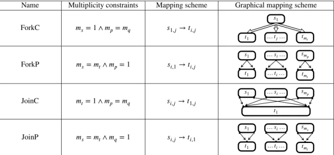
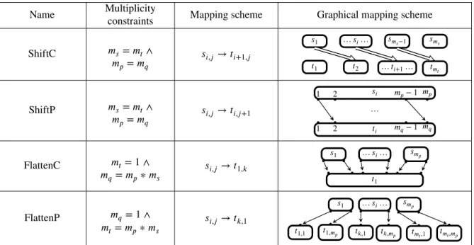
Tables 1, 2 and 3 give for each connection pattern the constraints on its elements multiplicities, the mapping scheme, and a graphical representation of the mapping scheme. The mapping scheme of a link is provided using the 𝑠𝑖,𝑗 → 𝑡𝑘,𝑙notation with default values for the 𝑖,𝑗,𝑘 and 𝑙 indices respectively taking their values in the intervals
[1, 𝑚𝑠],[1, 𝑚𝑝],[1, 𝑚𝑡], and [1, 𝑚𝑞]. Constraints provided in the tables can modify the values of the multiplicities and/or
the mapping scheme itself.
These tables can be extended to support additional connection patterns. For example, variants of Rotate could be parameterized by the number of shifts, shifting could be applied to ports or components or both.
Connection patterns may allow in the general case a join of multiple links to one port for example (as in the JoinP pattern in Table 2). It may or may not be possible to do any kind of links (e.g a join from 𝑛 ports to one port representing
𝑛water pipes pouring water to a single bucket; or preventing such connections on a dataflow model).
Remark. With respect to Tables 1, 2 and 3, the last column (Graphical mapping scheme) illustrates the links between
components inside a same component. When links connect ports of the parent component, either 𝑚𝑠and/or 𝑚𝑡should
Name Multiplicity constraints Mapping scheme Graphical mapping scheme Identity (Ident) 𝑚𝑝= 𝑚𝑞∧ 𝑚𝑠= 𝑚𝑡 𝑠𝑖,𝑗→ 𝑡𝑖,𝑗 𝑠1 … 𝑠𝑖… 𝑠𝑚𝑠 𝑡1 … 𝑡𝑖… 𝑡𝑚𝑡 FirstP 𝑚𝑝= 1 ∧ 𝑚𝑠= 𝑚𝑡 𝑠𝑖,1→ 𝑡𝑘,1 𝑠1 … 𝑠𝑖… 𝑠𝑚𝑠 𝑡1 … 𝑡𝑗… 𝑡𝑚𝑡 FirstC 𝑚𝑝= 𝑚𝑞∧ 𝑚𝑠= 1 𝑠1,𝑗 → 𝑡1,𝑙 𝑠1 𝑡1 … 𝑡𝑗… 𝑡𝑚 𝑡 LastP 𝑚𝑝= 1 ∧ 𝑚𝑠= 𝑚𝑡 𝑠𝑖,1→ 𝑡𝑘,𝑚 𝑞 𝑠1 … 𝑠𝑖… 𝑠𝑚𝑠 𝑡1 … 𝑡𝑗… 𝑡𝑚𝑡 LastC 𝑚𝑝= 𝑚𝑞∧ 𝑚𝑠= 1 𝑠1,𝑗 → 𝑡𝑚𝑡,𝑙 𝑠1 𝑡1 … 𝑡𝑗… 𝑡𝑚𝑡 Rotate 𝑚𝑝= 𝑚𝑞∧ 𝑚𝑠= 𝑚𝑡 𝑠𝑖,𝑗→ 𝑡(𝑖+1)%𝑚 𝑠,𝑗 𝑠1 … 𝑠𝑚𝑠−1 𝑠𝑚𝑠 1 𝑛1 𝑡1 𝑡2 … 𝑡𝑚𝑡 Transpose (Transp) 𝑚𝑝= 𝑚𝑡∧ 𝑚𝑠= 𝑚𝑞 𝑠𝑖,𝑗→ 𝑡𝑗,𝑖 𝑠1 … 𝑠𝑖… 𝑠𝑚𝑠 1 j 𝑡1 … 𝑡𝑗… 𝑡𝑚𝑡
The 𝑖,𝑗,𝑘,and 𝑙 indices take respectively their values in the intervals [1, 𝑚𝑠],[1, 𝑚𝑝],[1, 𝑚𝑡], and [1, 𝑚𝑞].
Table 1: Connection patterns
Application to the example. In the previous pattern mapping example (Fig. 10), we can now compute the value of the
nb_vinparameter based on the specification of the FlattenC (FlatC on the figure specified in Table 3) connection pattern of the link between the comp and the vote components. This connection pattern constrains the values of the multiplicities of the connected ports and components such that there is only one target component with a number of ports equal to the product of the number of source components with the number of source ports. The result is that the value of the nb_vin parameter is set to nb_out * nb_comp. Thus, if we chose nb_comp=3, we get nb_vin=6 and the model of Fig. 6 (b).
3.3. Pattern instance application
In the final step, the unfolded pattern instance can be applied to the model. Applying a pattern instance on a component comes to merging instance model elements into the user model while keeping mapped elements identical. In category theory, this operation can be seen as a push-out where mapped elements are identified.
In the case of the mapping of a pattern to a link, the application is done by:
• mapping the external input port of the pattern to the source port of the mapped link and; • mapping the external output port of the pattern to the destination port of the mapped link.
3.4. Pattern instantiation verification
A set of constraints shall be derived from the pattern and the mapping definitions. These constraints come from the multiplicity variables, the link types, the related multiplicity constraints, and the arity of the mapped model elements.
Name Multiplicity constraints Mapping scheme Graphical mapping scheme ForkC 𝑚𝑠= 1 ∧ 𝑚𝑝= 𝑚𝑞 𝑠1,𝑗→ 𝑡𝑖,𝑗 𝑠1 … 𝑡𝑗… 𝑡1 𝑡𝑚 𝑡 ForkP 𝑚𝑠= 𝑚𝑡∧ 𝑚𝑝 = 1 𝑠𝑖,1→ 𝑡𝑖,𝑗 𝑠1 … 𝑠𝑖… 𝑠𝑚𝑝 𝑡1 … 𝑡𝑖… 𝑡𝑚𝑡 JoinC 𝑚𝑡= 1 ∧ 𝑚𝑝= 𝑚𝑞 𝑠𝑖,𝑗→ 𝑡1,𝑗 𝑠1 … 𝑠𝑖… 𝑠𝑚𝑝 𝑡1 JoinP 𝑚𝑠= 𝑚𝑡∧ 𝑚𝑞 = 1 𝑠𝑖,𝑗→ 𝑡𝑖,1 𝑠1 … 𝑠𝑖… 𝑠𝑚𝑠 𝑡1 … 𝑡𝑖… 𝑡𝑚𝑡
The 𝑖,𝑗,𝑘,and 𝑙 indices take respectively their values in the intervals [1, 𝑚𝑠],[1, 𝑚𝑝],[1, 𝑚𝑡], and [1, 𝑚𝑞].
Table 2: Connection patterns (continued)
This set of constraints can then fed to a constraint solver such as CHOCO [PFL17]. There are three cases regarding the result of the constraint solving.
• If there exists exactly one solution for this set of constraints then the mappings of the pattern are considered correct.
• If there are multiple solutions, then the user should provide additional constraints to reach a single solution. This may be implemented as a feedback to the user pointing the variables that are not sufficiently constrained or by relying on default values for these variables.
• If there is no solution, then the mapping is not correct.
Based on the type of the connection pattern, variable values and names are constrained. For example, for the Identityconnection pattern, the values of input/output ports multiplicities should be the same. If it is not the case, then there are discrepancies in the constraints of the pattern. If a constraint establishes equality between two variable names then the variables are redundant.
Remark. Patterns instantiation are currently not checked for correction. In our prototype, we have implemented an ad
hoc solution where correct and complete mappings must be provided by the user.
4. A brief overview of Event-B
Figure 13: Event-B model structure The Event-B method allows the development of
correct-by-construction software systems [Abr10]. It sup-ports a formal development process based on a refinement mechanism with mathematical proofs. We take as ex-ample the framework we have developed to illustrate the structure of an Event-B project (Fig. 13). In this figure, boxes represent Event-B machines, rounded boxes con-texts, and arrows relations between these elements. Static data models are introduced incrementally through a chain of context extensions (here, with cModel as root). State
Name Multiplicityconstraints Mapping scheme Graphical mapping scheme ShiftC 𝑚𝑠= 𝑚𝑡∧ 𝑚𝑝 = 𝑚𝑞 𝑠𝑖,𝑗→ 𝑡𝑖+1,𝑗 𝑠1 … 𝑠𝑖… 𝑠𝑚 𝑠−1 𝑠𝑚𝑠 𝑡1 𝑡2 … 𝑡𝑖+1… 𝑡𝑚𝑡 ShiftP 𝑚𝑠= 𝑚𝑡∧ 𝑚𝑝 = 𝑚𝑞 𝑠𝑖,𝑗→ 𝑡𝑖,𝑗+1 𝑠𝑖 1 2 𝑚𝑝− 1 𝑚𝑝 … 𝑡𝑖 1 2 𝑚𝑞− 1 𝑚𝑞 FlattenC 𝑚𝑡= 1 ∧ 𝑚𝑞 = 𝑚𝑝∗ 𝑚𝑠 𝑠𝑖,𝑗→ 𝑡1,𝑘 𝑠1 … 𝑠𝑖… 𝑠𝑚𝑝 𝑡1 FlattenP 𝑚𝑞 = 1 ∧ 𝑚𝑡= 𝑚𝑝∗ 𝑚𝑠 𝑠𝑖,𝑗→ 𝑡𝑘,1 𝑠1 … 𝑠𝑖… 𝑠𝑚𝑝 𝑡𝑘,1 𝑡1,𝑚𝑝 𝑡1,1 𝑡𝑘,𝑚 𝑝 𝑡𝑚𝑡,1 𝑡𝑚𝑡,𝑚𝑝
The 𝑖,𝑗,𝑘 and 𝑙 indices take respectively their values in the intervals [1, 𝑚𝑠],[1, 𝑚𝑝],[1, 𝑚𝑡], and [1, 𝑚𝑞].
Table 3: Connection patterns (continued)
variables updated by events are introduced in machines (here, with mComponent as root) and subsequently refined. Each machine can access context data through the sees link.
Expressions and predicates. For the most part, Event-B expressions and predicates are denoted through standard set
theory and its usual set notation. However, some of them are specific to Event-B:
• pair construction: pairs are constructed using the maplet operator →. A pair is thus denoted 𝑎 → 𝑏 instead of (𝑎, 𝑏). The set of pairs 𝑎 → 𝑏 where 𝑎 ∈ 𝐴 and 𝑏 ∈ 𝐵 is denoted 𝐴 × 𝐵.
• A subset of 𝐴 × 𝐵 is a relation. The set of relations from 𝐴 to 𝐵 is denoted 𝐴 ↔ 𝐵 or (𝐴 × 𝐵). A relation
𝑟 ∈ 𝐴 ↔ 𝐵has a domain: 𝐝𝐨𝐦(𝑟) and a codomain: 𝐫𝐚𝐧(𝑟). When a relation 𝑟 relates an element of 𝐝𝐨𝐦(𝑟) with at most one element, it is called a function. The set of partial functions from 𝐴 to 𝐵 is denoted 𝐴 →𝐵, the set of total functions is denoted 𝐴 → 𝐵. The image of a set 𝐴 by a relation 𝑟 is denoted 𝑟[𝐴].
• The relation composition of two relations 𝑟1∈ 𝐴 ↔ 𝐵and 𝑟2∈ 𝐵 ↔ 𝐶is denoted as 𝑟1; 𝑟2.
• The direct product 𝑟1⊗ 𝑟2of relations 𝑟1 ∈ 𝐴 ↔ 𝐵1and 𝑟2 ∈ 𝐴 ↔ 𝐵2is the relation containing the pairs (𝑥 → (𝑦1→ 𝑦2))where 𝑥 → 𝑦1∈ 𝑟1and 𝑥 → 𝑦2∈ 𝑟2.
• domain restriction: 𝐷 ⊲ 𝑟 = {𝑥 → 𝑦 ∣ (𝑥 → 𝑦) ∈ 𝑟 ∧ 𝑥 ∈ 𝐷} • range restriction: 𝑟 ⊳ 𝐷 = {𝑥 → 𝑦 ∣ (𝑥 → 𝑦) ∈ 𝑟 ∧ 𝑦 ∈ 𝐷}
• overwrite: 𝑓⊲−𝑔 = ((𝐝𝐨𝐦(𝑓)∖𝐝𝐨𝐦(𝑔)) ⊲ 𝑓) ∪ 𝑔. For instance, such a notation is used to denote a new array obtained by changing the element of an array 𝑎 at index 𝑖: 𝑎⊲−{𝑖 → 𝑒′}.
Contexts. Contexts define abstract data types through sets, constants and axioms. The theorem clause expresses
facts that should be satisfied (derived) thanks to axioms. Clauses are expressed in first order set theory.
As an example, let us consider our root context cModel (Listing 1). It introduces a carrier set Model and three constants: Pattern, Mdl and Pat. Pattern and Mdl and Pat are then defined as elements of the disjoint sets Model ∖ Patternand Pattern.
Listing 1: Event-B context for models and patterns context cModel
sets Model
constants Pattern Mdl Pat axioms
@Pattern_ty Pattern ⊆ Model @Mdl_ty Mdl ∈ Model ⧵ Pattern @Pat_ty Pat ∈ Pattern
end
Listing 2: Machine example machinemModel sees cModel
variables mdls pats ofPattern // world variables invariants
@mdls_ty mdls ⊆ Model ⧵ Pattern // created models @pats_ty pats ⊆ Pattern // created patterns
// the mapping from created models to created patterns is a total function
@ofPattern_ty ofPattern ∈ mdls → pats theorem
@disj_mdls_pats mdls ∩ pats = ∅ // created patterns and created models are disjoint
Machines. Machines define symbolic labelled transition systems. The state of a transition system is defined as the
value of machine variables. Labelled transitions are defined by events specifying the new value of variables while preserving invariants. Moreover, as in contexts, the theorem clause expresses facts that should be satisfied (derived) thanks to axioms or invariants. A machine event (an event example is given in Listing 14) has three optional parts:
• parameters (any p1 ...pn),
• guards (where ...) specifying constraints to be satisfied by parameters and state variables, defined in first order set theory,
• and actions (then ...) specifying state variables updates.
In Event-B, the refinement proof obligations enforce a weak refinement semantics [Mil89, Hal08]. The listing 2 continued in listing 3 illustrates the different notions of a machine. It relies on the context given in listing (1).
Proofs. Proof obligations for well-formedness, invariant preservation, refinements and theorems are automatically
generated by the Rodin tool [ABH+10, Rod19]. They can be discharged thanks to automatic proof engines (CVC4, Z3, veriT) or through assisted proofs. These proofs assert that the development has been validated.
The model given by listing (2) requires to discharge one proof obligation expressing that each invariant is true ini-tially, four (two non trivial obligations for each event) invariant preservation proof obligations and one proof obligation for the theorem. All these proof obligations could be discharged automatically thanks to the Rodin theorem provers.
Execution model. Event-B has no behavioral semantics as such [Hal08]. However, since a machine can be seen as a
labelled transition system, its semantics is defined by its set of traces. Usually strong or weak fairness assumptions are added to restrict the set of admissible traces. However, in this paper, since we are mostly concerned by safety properties (structural properties of the transformed model), we have not dealt with fairness aspects.
In fact, with respect to execution, we have mainly considered termination properties. As we shall see in the para-graph Termination of Section 6.2.1, the termination of the unfolding process is asserted thanks to the introduction of a variant. Proof obligations ensure that events declared as convergent make the variant decrease. It follows that these events become disabled eventually.
Listing 3: Machine example events
event INITIALISATION then
@i mdls, pats , ofPattern ∶= ∅, ∅, ∅ // empty world end
event NewPattern anynewP where
@newP_ty newP ∈ Pattern ⧵ pats // newP does n ot exist yet then
@a pats ∶= pats ∪ {newP} // The pattern newP is created end
event NewModel anynewM P where
@newM_ty newM ∈ (Model ⧵ Pattern) ⧵ mdls // newM does n ot exist yet @P_ty P ∈ pats // P is an existing pattern
then
@a1 mdls ∶= mdls ∪ {newM} // The model newP is created @a2 ofPattern(newM) ∶= P // The pattern of newM is P end
end
5. Formal framework and component model
Our formal framework is modeled in Event-B which supports powerful data modelling capacities inherited from set theory and offers events as the unique control structure to define data evolution. Relying on Event-B, we describe our methodology and our component model in an incremental way.
5.1. Methodology
The aim of our work is to provide semantics for the application of patterns with multiplicities. This formal seman-tics is obtained through horizontal refinements [Abr10]. We first elaborate an initial machine dealing with our basic components. Then, through refinements, we introduce new machines dealing successively with components having properties, ports and links. The last machine can be considered as the specification of a pattern application and the starting point for code generation through vertical refinements [Abr96]. In the following, we give a global overview of the considered development, then, we detail the Event-B machines underlying this development. The Event-B development is available on the project forge4.
5.2. Incremental description of the component model
Since our focus is on system engineering, our basic entity is a model denoted by the set Model. Each model has its own components which belong to the set Component. Patterns are introduced as a subset of Model. Except for these base sets, modeling elements are introduced through machine variables as we intend to build and update models. These modeling elements will be introduced incrementally using a horizontal refinement-based approach. At first, we introduce components in the machine mComponent. A model is related to a finite set of components (illustrated by Listing 4)5. Each component belongs to at most one model. Furthermore, components associated to patterns have a multiplicity which will be used to parameterize the elaboration of pattern instances.
We adopt a hierarchical component model. We formalize the hierarchy property over the components of each model. The partial function container returns the parent of a component, if any. To be well defined, containment
4https://sahara.irt-saintexupery.com/MOISE/Pattern-Instanciation-On-System-Engineering-Model 5In Event-B, predicate labels are introduced by the @ symbol.
Listing 4: Models and components @comp components ∈ Model ↔ Component
@comp_finite ∀m⋅finite(components[{m}])
@comp_not_shared components−1∈ Component → Model
@c_mult c_multiplicity ∈ components[Pattern] → ℕ
should be acyclic. To ensure this property, we assume the existence of an irreflexive superset of the transitive closure of the container function: it is represented by the variable containers [DBA08]. Note that Event-B does not provide a transitive closure operator and even if it was available, using a super-set is sufficient and leads to simpler proof obligations (c.f. Listing 5).
Listing 5: Hierarchy of components @cont_ty container ∈ ran(components) → ran(components)
@cont_ctr components;container;components−1⊆id
@clos_ty containers ∈ran(components) ↔ ran(components) @clos_cont container ⊆ containers
@clos_trans containers ; containers ⊆ containers @clos_irrefl containers ∩ id = ∅
To support modular descriptions, a component defines a set of input or output ports (c.f. Listings 6 and 7). A base set Port, partitioned into input and output ports (IPort and OPort) is introduced in an extension cPort of the context cComponent.
Listing 6: Ports context context cPort extends cComponent sets Port
constants IPort OPort axioms
@part partition (Port , IPort ,OPort) end
Listing 7: Port invariants @port_ty ports ∈ ran(components) ↔ Port @port_finite ∀c⋅ finite ( ports [{c}])
@port_not_shared ports−1∈ Port → Component
@p_mult p_multiplicity∈ (components;ports)[Pattern] → ℕ
Listing 8: Link invariants
@link_ty links ∈ ran(components) ↔ Link @link_finite ∀c⋅ finite ( links [{c}]) @src_ty src ∈ ran( links ) → ran(ports) @dst_ty dst ∈ ran( links ) → ran(ports) Modeling elements related to ports are declared in a
refine-ment, named mPort, of the root machine. A port belongs to at most one component. Ports of pattern components have a mul-tiplicity. A base set Link is added in the context cLink. Our component model is refined (machine mLink) to add links be-tween pairs of ports. A link is also defined through its source and destination ports. For this purpose, we introduce the src and dst functions (Listing 8).
The direction of links must be compatible with the one of its source and destination ports. A link can connect a component port and a sub-component port or two sub-component ports, which leads to four cases (graphically pictured in Fig. 14 and formalized in Listing 9):
(1) If an input port is connected to an output port, these ports belong to the same component. Thus, the source and destination ports, supposed to be an input and an output, are ports of the component to which the link is attached (constraint link_cio in Listing 9).
(2) If a link of a given component connects an input to an input, its source is a port of this component and its destination is a port of a direct sub-component (constraint link_cii).
(3) A link between an output port and an input port connects two components (possibly the same component for a feedback link) contained in the same parent component (constraint link_coi).
Listing 9: Connection constraints
@link_cii links ; (( src ⊗ dst) ⊳ (IPort × IPort )) ⊆ ports ⊗ (container−1; ports)
@link_coi links ; (( src ⊗ dst) ⊳ (OPort × IPort)) ⊆ (container−1;ports) ⊗ (container−1; ports)
@link_coo links ; (( src ⊗ dst) ⊳ (OPort × OPort)) ⊆ (container−1; ports) ⊗ ports
@link_cio links ; (( src ⊗ dst) ⊳ (IPort × OPort)) ⊆ ports ⊗ ports
(4) Finally a link from an output port to an output port connects a component to its parent component (constraint link_coo).
We comment these constraints by expanding the formula labelled link_cio6 links; ((src ⊗ dst) ⊳ (IPort × OPort)) ⊆ ports ⊗ ports ≡ ∀ 𝑐 𝑝1𝑝2⋅ (∃𝑙.𝑐 → 𝑙 ∈links ∧ 𝑝1=src(l) ⏞⏞⏞⏞⏞⏞⏞⏞⏞⏞⏞⏞⏞ 𝑙→ 𝑝1∈src ∧ 𝑝2=dst(l) ⏞⏞⏞⏞⏞⏞⏞⏞⏞⏞⏞⏞⏞ 𝑙→ 𝑝2∈dst ∧𝑝1∈IPort ∧ 𝑝2∈OPort) ⇒ 𝑐 →(𝑝1→ 𝑝2) ∈ports ⊗ ports
≡ ∀ 𝑐 𝑙. 𝑐 → 𝑙 ∈links ∧ src(𝑙) ∈ IPort ∧ dst(𝑙) ∈ OPort ⇒ 𝑐 →src(𝑙) ∈ ports ∧ 𝑐 → dst(𝑙) ∈ ports
which can be read as the source and destination ports belonging to the same c component.
The presence of links between components and ports with multiplicities impose constraints on these multiplicities. Multiplicities are attached to ports and components of the subset Pattern of Model. Pattern links must be coherent with these multiplicities and depend on the nature of the link.
Root SC1 SC2 (1) I O (2) I I O(3) I O (4) O
Figure 14: Component (I/O) ports links
We only consider here (Listing 10) Transpose links which should connect instance port number 𝑖 of instance com-ponent number 𝑗 to instance port number 𝑗 of instance comcom-ponent number 𝑖 where 𝑖 and 𝑗 are in the range of pattern port and component multiplicities. To make unfolding possible, the multiplicity of the source port should be equal to the multiplicity of the target component, and conversely.
Listing 10: Multiplicity constraints
@transp_src ∀l⋅ l ∶(components;links)[{Pat}]∩Transpose ⇒ p_multiplicity ( src ( l )) = c_multiplicity ( ports−1(dst(l )))
@transp_dst ∀l⋅ l ∶(components;links)[{Pat}]∩Transpose ⇒ p_multiplicity (dst( l )) = c_multiplicity ( ports−1(src(l )))
Properties (e.g. requirements, tests, constraints) may be associated to components, ports and links. We thus have defined the Property set, the elements of which are attached to components through the cProperties relation. We have only considered here properties attached to components.
The invariant properties that we have introduced apply either to specific models (patterns when multiplicities are concerned) or to any model. The events we will present now let patterns unchanged, but create instances and update
user models. They should thus establish or preserve these well-formedness properties. Three identifiers are introduced to designate these models: Pat for a pattern, Inst for a pattern instance and Mdl for a user model. These identifiers are declared as constants but they designate models defined through the variables introduced by the successive refinements, which allow them to evolve.
6. Pattern application in Event-B
We study the application of domain specific design patterns to produce refinements of architecture models and ensure that the produced model including the instantiated pattern is a structurally correct refinement. We present the successive steps, illustrated by Fig. 15, needed to perform pattern application in an iterative way. In this figure, loops express the repeated firing of events during the top down traversal of the pattern structure.
initialize_pattern
unfold_root_c unfold_node_c apply_pattern
elaboration step
Figure 15: Pattern application steps
It is important to note that two potentially independent operations are performed:
• Pattern instantiation which only depends on multiplicities which are provided either by pattern-model mapping or by information attached to new model elements. Pattern instantiation builds a pattern instance through the initialization and the elaboration steps.
• Pattern instance application (the apply_pattern step) which relies on mappings between a pattern instance and a model. The guards of this event and its refinements express sufficient conditions over mappings so that the built model satisfy soundness constraints expressed as model invariants. Hence, the built model is correct by construction.
6.1. Pattern initialization step
The initialize_pattern event instantiates the parameters of the pattern and identifies the root components of the pattern. This event is enriched in each refinement. Each refinement level introduces new constraints over pattern-model mappings by extending the event guard.
6.1.1. Component and ports level
Component (resp. port) mapping between the pattern and the source model are provided. They allow for the extraction of component (resp. port) multiplicities based on the number of source model elements mapped to the considered pattern element. However, a model element is mapped to at most one pattern element. Additional explicit pattern components (resp. ports) multiplicities are also provided by the user.
6.1.2. Link level
Finally, at the link level, link mappings are provided and multiplicity constraints are checked depending on the link semantics (c.f. multiplicity constraints provided in Table 1).
𝑠𝑐1 𝑠𝑐𝑝 c n 𝑠𝑑 dest Pat Inst to_unfold_c_in
(a) before unfolding c in dest
𝑠𝑐1 𝑠𝑐𝑝 n 𝑖1 𝑠𝑑 𝑖𝑛 c dest Pat Inst to_unfold_c_in (b) after unfolding
Figure 17: Unfolding component c in (non empty) component dest
6.2. Instance elaboration step
This step is initiated by the unfold_root_c event which marks root components to be unfolded. Then, the event unfold_node_cexpresses the recursive elaboration of a pattern along these two dimensions. An auxiliary state variable is introduced to store components to be unfolded in the next iterations of the replication process. These events are enriched in each refinement.
6.2.1. Component level 𝑠𝑐1
𝑐
𝑠𝑐𝑝 𝑛 ⇐⇒ 𝑐1 ... 𝑐𝑛 i2p_c to_unfold_c_in Pat InstFigure 16: Unfolding roots
Root components unfolding. The initialize_pattern event
as-signs the variable to_unfold_c with the set of root components of the pattern (those without parent containers). The unfold_root_c event takes such a component c and creates the associated instance compo-nents 𝑐1,… , 𝑐𝑛, where 𝑛 is the multiplicity of c. The event adds the
pairs (𝑠𝑐𝑖, 𝑐𝑗) for each subcomponent 𝑠𝑐𝑖 and 𝑗 ∈ 1..𝑛 to the relation
to_unfold_c_inused in the next step. Links between instance and pattern components are stored in i2p_c (Fig. 16).
Sub-component unfolding. This step (Fig. 17) is fired by a couple (c, dest) in to_unfold_c_in. It creates as
subcomponents of dest new instances 𝑖1,… , 𝑖𝑛of c, the number of which corresponding to its multiplicity. The
component dest may contain already created subcomponents originating from the unfolding of brothers of 𝑐. As for root component unfolding, the pairs (subcomponent of c, newly created instance) are added to to_unfold_c_in. The recursive unfolding is thus carried on.
Termination. Event-B checks the termination of the unfolding process thanks to the introduction of a variant. As
a variant, we have considered the complement of the set of paths of created instances. A path is introduced as a partial function from the finite set of component patterns to indexes over the interval 1..𝑀 where 𝑀 is the maximal multiplicity of pattern components. The function c_indexes maps each instance to its path, the set of instances being the domain of the function inst2pat_c. The set of such (partial) functions is finite. Thus, the variant
(components[{𝑃 𝑎𝑡}] ↛ 1..𝑀) ⧵ c_indexes[𝐝𝐨𝐦(inst2pat_c)] is accepted and proved to decrease.
6.2.2. Port level
The sub-component identification step is enriched by storing in to_unfold_p_in ports to be unfolded and their destination component. The new event unfold_p processes these elements. Ports are created with the same direction as the pattern port and linked to the instance component. The variable i2p_p stores mappings between instance and pattern ports. The termination is step is again ensured by a variant which is defined to be the to_unfold_p_in set. The event unfold_p is declared to be convergent. Actually, the variant is decremented for each triggering of the unfold_pevent.
Listing 11: Link Unfolding @links links ∶= links ∪ ({c} × ran(new_l))
@nsrc src ∶= src ∪ {ip , ic ⋅ ip → ic ∈ dom(new_l) ∣ new_l(ip→ic) → spi( sci ( ic ))( ip)} @ndst dst ∶= dst ∪ {ip , ic ⋅ ip → ic ∈ dom(new_l) ∣ new_l(ip→ic) → dpi(dci ( ip ))( ic )}
6.2.3. Link level
Link creation within a given instance component 𝑐 occurs after its sub-components unfolding. For this purpose, four injective mappings, indexed by multiplicities, are declared from pattern source and destination components and ports to sub-components of 𝑐 and their input or output ports. As a consequence, we only consider here links between two sub-components, not redirection links between a component and a sub-component, or cross-links from an input to an output of a component. In the Event-B model, we only consider transpose links. The corresponding multiplicity constraint is added and the array of links is created (Listing 11). We can see the four mappings (sci, spi, dci, dpi) to source (s) then destinations (d) components (c) and ports (p) instances (i) and the newly created links (new_l).
6.2.4. Properties
When elements (components, ports or links) are duplicated, their associated properties are also duplicated. This is done in the mProperty machine where the unfolding events are refined. An example of such a refinement for the unfold_root_cevent is provided in Listing 12. A similar refinement is applied for the replication of properties for ports and links in the respective events.
Listing 12: Properties replication for components event unfold_root_c extends unfold_root_c
then
@prop cProperties ∶= cProperties ∪ (ran(new_c)×cProperties[{c}]) end
6.2.5. Instantiation properties
Properties of pattern instantiation are stated as invariants (Listing 13). We have already expressed that the instance model (as well as any model) is well structured. We have added additional properties stating that pattern and instance models seen as labelled graphs are bisimilar with respect to the component-to-component relation container, the component-to-port relation ports, the link-to-port relations src and dst and specified the semantics of transpose links:
Listing 13: Instance properties @inst2pat_cont inst2pat_c;container = container;inst2pat_c @inst2pat_comp inst2pat_p;ports−1= ports−1;inst2pat_c
@inst2pat_l_src inst2pat_l; src = src;inst2pat_p @inst2pat_l_dst inst2pat_l;dst = dst;inst2pat_p
@transp_correct1 ∀l ⋅ l ∈ (components;links)[{ Inst }] ∩ Transpose ⇒ p_index(src( l )) = c_index(ports−1(dst(l)))
@transp_correct2 ∀l ⋅ l ∈ (components;links)[{ Inst }] ∩ Transpose ⇒ p_index(dst(l )) = c_index(ports−1(src(l)))
6.3. Instantiated pattern application step
Pattern application is specified by the event apply_pattern initially defined for component-only models and then incrementally refined to support ports and links. This event applies the pattern instance obtained through the preceding step to the user-supplied model. This event is enriched in each refinement:
Inst Mdl inst_comp inst_comp inst_comp new_comp new_comp new_comp Figure 18: Pattern application
Listing 14: Instance application at Component level eventapply_pattern // model transformation
anyinst_components // instance mapping new_components
where
@ic inst_components ∈ components[{Inst}] ↣ components[{Mdl}]
@nc new_components ∈ components[{Inst}] ⧵ dom(inst_components) ↣ Component ⧵ ran(components) @acycl_inst_components dom(inst_components) ⊲ container;inst_components ⊆ inst_components;container @acycl_container container [dom(inst_components)] ⊆ dom(inst_components)
then
@m components ∶= components ∪ ({Mdl}×ran(new_components))
@f container ∶= container ∪ (new_components−1;container;(inst_components ∪ new_components))
@c containers ∶= containers ∪
(new_components−1;containers;(new_components ∪ inst_components);(containers ∪ id))
end
6.3.1. Component level
Pattern instance application (Listing 14) is fired by providing a mapping inst_components from instance com-ponents to model comcom-ponents.
Unmapped components (not belonging to the interface), designated by the new_components identifier, will be created and inserted into the set of components of the model. The container function of the model is updated to take into account containment information coming from the pattern instance (Fig. 18).
The main point is to show that invariant properties are preserved, one of them being the acyclicity of the contain-ment relationship. Some hypotheses (@acycl_inst and @acycl_container) are needed to avoid merging a graph and its inverse: if an instance component is mapped to a model component and has a container, this container should be mapped to the container of the model component. The acyclicity proof is then automatic once the update of the superset of the transitive closure of the new container function has been provided. The added hypotheses ensure that the pattern instance is inserted as a subtree of the user model.
6.3.2. Properties
Properties attached to pattern components are transferred to their corresponding model components (Listing 15). However, if pattern properties are instantiated by model properties, these ones are used instead.
6.3.3. Port and link levels
Instance pattern application is extended to ports by two different events: apply_pattern dedicated to component transformation and apply_link_pattern dedicated to link transformation (see Listing 16). They both use the same code schema as for components. Container update is replaced by port-to-component update. Furthermore port mapping
Listing 15: Instance application at Property level event apply_pattern extends apply_pattern
anyinst_props where
@inst_prop inst_props ∈ Property → Property // pattern properties to model properties then
@prop cProperties ∶= cProperties ∪
((inst_components ∪ new_components)−1;cProperties; (id ⊲− inst_props))
end
Listing 16: Link transformation event apply_link_pattern extends apply_link_pattern
any inst_links new_links where
@inst_links_ty inst_links ⊆ links [{comp}] @inst_src src [ inst_links ] = dom(src_ports) @inst_dst dst [ inst_links ] = dom(dst_ports)
@nl new_links ∈ (components;links)[{ Inst }] ↣ Link ⧵ ran( links ) then
@s src ∶= ( inst_links ⩤ src) ⊲− (new_links−1;src;new_ports)
@d dst ∶= ( inst_links ⩤ dst) ⊲− (new_links−1;dst;new_ports)
@l links ∶= ( links ⩥ inst_links) ∪ ((inst_components∪new_components)−1;links;new_links)
end
and new ports should preserve port direction. In the same way, links are considered and link to port attachments are made consistent.
6.4. Verification
As said in Section 4, in Event-B, the verification process consists in proving the proof obligations that have been automatically generated by the tool Rodin. In the following table, we give the count of proof obligations generated for each refinement level.
Machine Events Guards Proof obligations
mComponent 4 12 137
mPort 6 24 60
mLink 7 30 125
Most of the generated proof obligations have been discharged. Some have been discharged automatically. Oth-ers required interactive proof through explicit case analysis and/or hypothesis instantiation and rewriting. However, properties linked to finiteness and cardinals are not well supported by Rodin and by SMT solvers. It follows that these properties have been checked manually.
It is interesting to remark that over the last years, the proving effort has been made easier thanks to SMT solvers. However, the structuring approach provided by the incremental introduction of all the problem aspects remains essen-tial. In Event-B, this process is supported by the notion of horizontal refinement.
7. OCaml-based and Eclipse-based prototypes
While the previously depicted formalization is the core of our proposal, we decided to implement it using classical means and not to produce the implementation by refining the Event-B model until it can be implemented or code can
be generated from it7.
We decided to rely on an external implementation of the concepts using tools allowing for the definition of a quickly usable and demonstrative implementation. An OCaml-based tool implements pattern application. We also provide a first graphical editor for patterns and components as a set of Eclipse plugins8.
7.1. Architecture of the OCaml-based prototype
We thus decided to develop the pattern application mechanism as an OCaml program (Figure 19) which outputs the resulting component model in a format allowing an automatic layout thanks to ELKJS and TikZ. The whole process is self generated and presented in Figure 20.
Figure 19: Architecture of the OCaml pattern application tool
Figure 20: Architecture of the OCaml-based prototype
The OCaml part takes as input a pattern, a model, a mapping between them and generates a new model obtained by applying the instantiated pattern to the source model. All multiplicities are supposed to be provided by the mapping and thus are not derived from the source model. Thus, information from the input pattern and mapping is used to build the pattern instance and its associated mapping where links to the model have been duplicated in accordance to pattern unfolding rules. Then, the instantiated pattern is applied to the model by using mapping links. The various models are output in JSON format for ELKJS [Ope17] processing. Its layered layout algorithm adds positioning information to the JSON model which is in turn converted to LATEX TikZ format and ultimately to pdf. All the examples shown in the paper have been designed and processed thanks to this tool chain.
7.2. Pattern application example
We illustrate the capacities of our pattern application tool by considering a rather complex pattern: the Recovery Block Pattern (RBP) represented by Figure 21. A sequence of independent and functionally equivalent versions is provided. A version is triggered when a fault is detected on the previous version, thus ensuring fault tolerance [Arm10]. The ShiftC link type is used to specify that the 𝑖𝑡ℎtest block is connected to the (𝑖 + 1)𝑡ℎversion. The JoinC link type
merges the outputs of all test components given that only one of the outputs is active. The ForkC link type distributes the entry to all versions.
Listings 18, 17, 19 are an example of a source file processed by our OCaml prototype. It contains a source compo-nent model (test in listing 18) with two subcompocompo-nents: the RBP pattern (in listing 17) with multiplicity parameters enclosed by brackets and transformation request (in listing 19) specifying the subcomponent sc1 on which the pattern RBPshould be applied. Multiplicities and port mappings are also provided.
7We note that usual code generators [MS11] restrict the use of control and data structures, e.g., no any statement, only enumerated sets. 8Available at https://sahara.irt-saintexupery.com/MOISE/Pattern-Instanciation-On-System-Engineering-Model
Figure 21: The Recovery Block Pattern
Listing 17: Pattern specification processed by the OCaml prototype (2) pattern RBP(in i[nb_in], out o[nb_out]) {
componentVersion[nb_v](in i[nb_in], in err , out o[nb_out]) componentTest[nb_v](in i[nb_out], out o[nb_out], out err ) componentInit(out err )
i –{ForkC}→ Version.i Version .o –{ Identity }→ Test.i Test .o –{JoinC}→ o
Test . err –{ShiftC}→ Version. err Init . err –{ FirstC}→ Version. err }
Listing 18: Source model processed by the OCaml prototype (1) componenttest(in i1 , in i2 , out o1) {
component sc1(in i1, in i2 , out o1, out o2) component sc2(in i1, in i2 , out o)
i1 → sc1.i1 i2 → sc1.i2 sc1 .o1 → sc2.i1 sc1 .o2 → sc2.i2 sc2 .o → o1 }
Listing 19: Pattern application processed by the OCaml prototype (3) transform test . sc1 using RBP {
multiplicity nb_in → 2 nb_out → 2 nb_v → 2 mappings i1 , i2 → i𝑖 o1,o2 → o𝑜 }
The source model, the pattern, its instance given the provided multiplicities and the resulting model are displayed thanks to the ELKJS layered layout library (see Figure 22).
7.3. Towards an Eclipse Integration
After the production of the Ocaml implementation, we decided to develop an Eclipse integrated version of our framework including textual and graphical editors for patterns and components models.
We have produced a formalization of the structure of components and patterns as Ecore metamodels. We rely on this formalization for the development of tools allowing to create, edit and display model instances.
Figure 22: Model resulting from the application of the Recovery Block Pattern
Metamodel
The Eclipse ecosystem provides a wide variety of modeling languages and tools. The data structure designed to store hierarchical components and patterns has been encoded as an Ecore metamodel whose overview is provided in Figure 24.
The main classes of the metamodel are Component, Link, and Port. The Component class is the main con-tainer of the model and supports hierarchy through its element reference. Then a number of abstract classes (classes with an "a" decorator on their icon in Figure 24) used for factoring features of the concrete model elements are also provided. Values for Port directions and pattern Link types are provided as enumerations. The Pattern specific extension for multiplicity variables is stored in the MultiplicityElement class whose name attribute is inher-ited from the NamedElement abstract class. Port and Component elements are replicable (information modelled in the IsReplicable abstract class) and optionally reference a MultiplicityElement object. Finally, Model and Patternspecialize Component and respectively represent component models and patterns.
The metamodel also contains constraints specifying static correction properties of instance models. For instance, generic metamodels constraints ensure that attributes are correctly set (set to an actual value with a specific data type). Additional constraints attached to Link elements can express that src and tgt references from a Link elements are Port elements from either: (a) components of the same hierarchy level, or (b) a component and its container. This constraint ensure that correct model instances of the metamodel remains coherent with the previously provided formalization. Other constraints ensure that the distinction is done between Model elements and Pattern elements.
Graphical editors for models
We relied on the Sirius9toolset for the development of two graphical editors, one for patterns models and one for component models. The editors are based on the previously depicted metamodel and available on the project forge. Figure 23 is an example of the N-Version Programming pattern modelled inside the Sirius editor. A newer version of the Sirius toolset now features ELK10as a graphical model layout framework. It allows for the adaptation of layout algorithms to specific model editors. This feature is of principal interest as it allows for the automatic generation of the graphical representation of generated model and thus allows us to rely on our Sirius editor as a model visualization mean.
8. Related work
As noticed in the introduction, patterns are used in many stages of the development process. It follows that dif-ferent use of patterns have been investigated in a number of papers. These uses concern either structural aspects or dynamic aspects. With respect to structural aspects, refinement patterns are transformation rules that construct a model refinement. Usually, such refinements deal with properties over data structures, e.g., arrays, trees. In [Req08]
9https://www.eclipse.org/sirius/ 10https://www.eclipse.org/elk/
Figure 23: N-Version Programming pattern view in the Sirius editor
and [ITLR10], dedicated languages for the expression of such refinement patterns are proposed. Also, in [HFA13], patterns are defined as usual Event-B machines that are mapped on the Event-B machines to be refined.
With respect to dynamic aspects, refinement patterns concern the dynamic behaviour. As a matter of fact, tem-poral patterns have been proposed by [DAC99] to promote the use of temtem-poral logics for behavioural specifications. [SBFB17] study how some of these patterns can be transformed automatically as Event-B machines to be refined.
Some, like [ACdL96], provides a formalism for software design patterns where parameters of the application of the pattern are made explicit. Others, like Denney et al [DP15] provide a way to express generic and variable design patterns for safety cases models. [PVM+09] provide a more generic approach where variability is woven into the metamodel that may allow to produce variable pattern models for domain specific instances. [DFB+15] propose an approach where variability is handled using a dedicated language and variability can be applied to models. This approach is, as the previous one generic and allows for an independent formalization of the variability section of the problem and the handling of instances generation. Also, we mention [LNML+16], they use patterns to assess and compare several candidate architectures. They are especially concerned by quantitative aspects. It is interesting to remark that the analysis of variants raises complex metrics issues. We envision that a formal support could be a solution to assess the proposed solutions.
Also, in a context closer to ours, with respect to the underlying component model, [MD17] consider dynamic properties of patterns. However, their approach is based on model checking and consequently follows a translation validation approach whereas we follow a transformation verification approach. Last, we remark that a pioneering work advocating a formal approach, especially for architectural design patterns, is [ACdL96, DACY07]. A behavioral semantics for patterns is considered thanks to TLA: the Temporal Logic of Actions [Lam02] and the behavioral cor-rectness of the composition with respect to safety and fairness properties is proven. To the best of our knowledge, this work has not been mechanized.
Last, we mention the work of [MG18]. It is also close to our work since it relies on an interactive theorem proving approach based on Isabelle-HOL [WPN08]. While [MG18] propose a component model less elaborated than ours since it consists only in interfaces : sets of input and output ports as well as component parameters; They do neither consider hierarchy nor multiplicities. However, we remark that their model allows for the specification of architectural constraints specified in linear temporal logic expressed through formulae over the ports of the interface.
9. Conclusion
The work presented here results from exchanges with safety system engineers. Safety analysis leads to the identi-fication of weaknesses in the system architecture. Specific design patterns selected among those solving the identified safety issues are then applied to fix these weaknesses. This work is a study for supporting such a workflow.
We have chosen Event-B as a meta-modelling framework and used it to express a semantics for component models usually adopted by Model Based System Engineering frameworks [Voi17, DPW17]. We have presented an Event-B specification of two main operations needed to support the process: pattern instantiation taking into account variability and pattern instance application to the user model. These operations are modeled in an incremental way based on horizontal refinements, and are shown to preserve basic structural properties of the component model. Using this framework, we have defined a semantics for the definition, the instantiation and the application of patterns. We remark that rather than focusing on patterns applied on Event-B models, our objective is the formalization of the instantiation
Figure 24: Components and patterns metamodel
and the application of patterns for system architectures expressed using component models, by using Event-B. To make pattern library reusable, we provide a limited form of variability management through the introduction of multiplicities attached to some pattern modeling elements.
As in [DPW17], patterns are defined by adding multiplicities to modeling elements, and a pattern application algorithm is proposed. However, we consider component models, not argumentation models, and our formalization is incremental (through horizontal refinements); besides its dynamics has been formalized through Event-B events. Thus, pattern elaboration and application are not monolithic algorithms and can be extended through refinement. As a consequence, correctness proofs can also be of finer grain.
As future work, several improvements could be envisioned. The variability model could be enhanced to support alternative relations between model elements. For instance, exclusion would have to be expressed through proper-ties over multipliciproper-ties. We see two ways of adding this: the introduction of classical product line require/exclude constraints written in the pattern, or the implementation of a dedicated alternative operator. An explicit alternative operator is not necessary when requires/exclude constraints exist. Such constraints may also be extended to allow for more complex relations between multiplicities [QRD13, CK05]. However, as suggested in 3.4, constraint solvers could be used to synthesize multiplicity parameters and alleviate user interactions in the pattern instantiation process.
The formal specification of functional or non functional requirements would enable the formal verification of argu-mentation built together with pattern applications. The verification of these building blocks can be done once, which

![Figure 7: Monitor actuator pattern extract from [PKK15]](https://thumb-eu.123doks.com/thumbv2/123doknet/14219689.483447/7.892.170.727.245.464/figure-monitor-actuator-pattern-extract-from-pkk.webp)