Publisher’s version / Version de l'éditeur:
Journal of the Acoustical Society of America, 92, 3, pp. 1452-1460, 1992-09
READ THESE TERMS AND CONDITIONS CAREFULLY BEFORE USING THIS WEBSITE.
https://nrc-publications.canada.ca/eng/copyright
Vous avez des questions? Nous pouvons vous aider. Pour communiquer directement avec un auteur, consultez la première page de la revue dans laquelle son article a été publié afin de trouver ses coordonnées. Si vous n’arrivez pas à les repérer, communiquez avec nous à PublicationsArchive-ArchivesPublications@nrc-cnrc.gc.ca.
Questions? Contact the NRC Publications Archive team at
PublicationsArchive-ArchivesPublications@nrc-cnrc.gc.ca. If you wish to email the authors directly, please see the first page of the publication for their contact information.
NRC Publications Archive
Archives des publications du CNRC
This publication could be one of several versions: author’s original, accepted manuscript or the publisher’s version. / La version de cette publication peut être l’une des suivantes : la version prépublication de l’auteur, la version acceptée du manuscrit ou la version de l’éditeur.
Access and use of this website and the material on it are subject to the Terms and Conditions set forth at
Sound transmission through two kinds of porous concrete blocks with attached drywall
Warnock, A. C. C.
https://publications-cnrc.canada.ca/fra/droits
L’accès à ce site Web et l’utilisation de son contenu sont assujettis aux conditions présentées dans le site LISEZ CES CONDITIONS ATTENTIVEMENT AVANT D’UTILISER CE SITE WEB.
NRC Publications Record / Notice d'Archives des publications de CNRC:
https://nrc-publications.canada.ca/eng/view/object/?id=94ee04d2-fdc7-46f0-8831-7fb23fbf5ca1 https://publications-cnrc.canada.ca/fra/voir/objet/?id=94ee04d2-fdc7-46f0-8831-7fb23fbf5ca1
Sound transmission through two kinds of porous concrete blocks with attached drywall.
by
A.C.C. Warnock
National Research Council Canada Institute for Research in Construction ABSTRACT
The airflow resistance of concrete blocks plays a significant role in determining sound transmission losses for block walls with drywall added on furring. Two blocks types were tested. One was so porous that sound passed easily through it and there was no sign of a mass-air-mass resonance behind the added drywall. Such blocks must be plastered else their contribution to the attenuation of sound is very small. Once plastered, the low porosity increased the effective depth of the air cavity behind the added drywall on the unplastered side with attendant
increases in sound transmission loss. The mass-air-mass resonance occurred at a lower frequency corresponding to the distance from the drywall through the block to the plaster. The other block type tested had a higher airflow resistance that added a loss mechanism to the wall systems; the mass-air-mass resonance was damped and transmission loss was not reduced by the resonance. The benefits of having drywall added on furring were still obtained with these blocks. Their sound transmission losses were increased when plaster was applied on one face but the increase was not so great as for the very porous blocks. Airflow resistance is an important parameter that should be considered when designing block walls.
RÉSUMÉ
La résistance des blocs en béton au passage de l'air joue un rôle important dans la détermination de la perte de transmission sonore provoquée par les murs en blocs comportant une paroi de plâtre sur tasseaux. Les essais ont porté sur deux types de blocs. Le premier présentait une porosité suffisante pour que l'air passe
facilement; par ailleurs, on n'a décelé aucun signe de résonance masse-air-masse derrière la paroi de plâtre. Lorsqu'ils ne sont pas enduits de plâtre, ces blocs contribuent très peu à l'affaiblissement acoustique. Après qu’ils ont été plâtrés, leur faible porosité a fait augmenter l'épaisseur effective de la lame d'air se trouvant derrière la paroi de plâtre, du côté non enduit, ce qui s’est traduit par une plus grande perte de transmission sonore. La résonance masse-air-masse s'est produite à une fréquence plus basse correspondant à la distance entre la paroi de plâtre sur blocs et l'enduit. Le second type de bloc testé présentait une plus grande résistance au passage de l'air, ce qui a introduit un autre mécanisme de dissipation de l’énergie vibratoire, dans les murs; la résonance masse-air-masse a été amortie et n'a pas réduit la perte de transmission sonore. Dans ce cas, la pose d'une paroi de plâtre sur tasseaux est restée bénéfique. La perte de transmission sonore a
dans le cas des blocs très poreux. La résistance au passage de l'air est un paramètre important à prendre en compte lors de la conception des murs en blocs de béton
INTRODUCTION
A previous paper1 presented sound transmission loss data for normal weight concrete blocks with drywall attached to the block surface in different ways. The depth of the air cavity behind the drywall and the presence of sound-absorbing material in the cavity were shown to be important. Reductions in transmission loss at low frequencies were obvious and were attributed to a resonance involving the drywall, the air in the cavity and the blocks: the mass-air-mass resonance. The position of the resonance was not always clear, however, and to deal with this, the idea of a crossover frequency, fx, was introduced. (This is the frequency where the transmission loss curve for the blocks with added drywall crosses over and rises above the curve for the bare blocks.) Below fx, transmission loss is reduced relative to the bare block result; above fx, sound transmission loss is increased relative to the bare block result. For normal weight block walls, fx is given by
fx=K/(M d)1/2 (1)
where M is the surface mass of the drywall, kg/m2, and d is the depth of the cavity behind it, meters. K is 108 for an empty cavity and 60 for a cavity filled with fibrous sound-absorbing material.
In the Tenth Sir Richard Fairey Memorial Lecture, Heckl2 presented results from reference 3 to show that there can be an advantage to using porous stone or block as part of a double wall. The effective cavity depth behind the surface layer, usually drywall or something similar, is increased because of the porosity and the mass-air-mass resonance moves to a lower frequency. Not discussed in Ref. 2 was the idea that the airflow resistance of the porous wall material might also increase energy dissipation in the wall cavity and reduce the depth of the mass-air-mass resonance. Increasing airflow resistance will offset, however, the increase in effective cavity depth resulting from porosity. This suggests there may be an optimum value of airflow resistance for block walls when they are used as the core layer in a system incorporating drywall.
Watters4 presented data for single-withe block walls and discussed the importance of the block porosity. For the blocks he looked at, he concluded that many
lightweight-aggregate concrete blocks would not require sealing to ensure that there was no significant sound transmission due to porosity. The airflow
resistance was high enough that sound propagating through the pores of the block would be greatly attenuated and would be negligible compared to sound
propagating as vibration in the concrete. Sabine5 presented data for several painted and unpainted block walls. He found that unpainted walls with an airflow resistance of about 6 acoustic ohms or less suffered a reduction in transmission loss because of sound transmission through the pores of the block. The
transmission losses increased when such blocks were painted. Williamson and Mackenzie6 found similar results for walls constructed from 4-inch concrete blocks with a wide range in flow resistance.
Mackenzie et al.7 reported transmission loss data for block walls that had
surface. The data showed the detrimental effects of the mass-air-mass resonance and that the cement coat under the drywall made this worse. The block porosity reduced the negative effects of the mass-air-mass resonance. The authors
concluded that, for the blocks they used, plasterboard alone was sufficient to seal the surface of the blockwork. The data presented below show that this conclusion cannot be extended to all types of block.
It might be possible to produce simple mathematical models that will predict some of the effects described in the references above and those to be presented here. This paper does not do this. It merely presents sound transmission loss data for two types of concrete block: very porous blocks manufactured using a wood fiber aggregate, and lightweight blocks manufactured using slag aggregate. While the data do not allow the specification of an optimum value of airflow resistance for blocks, they do illustrate some effects block porosity or block airflow
resistance have on sound transmission loss for block walls.
I. MATERIALS A. Block properties
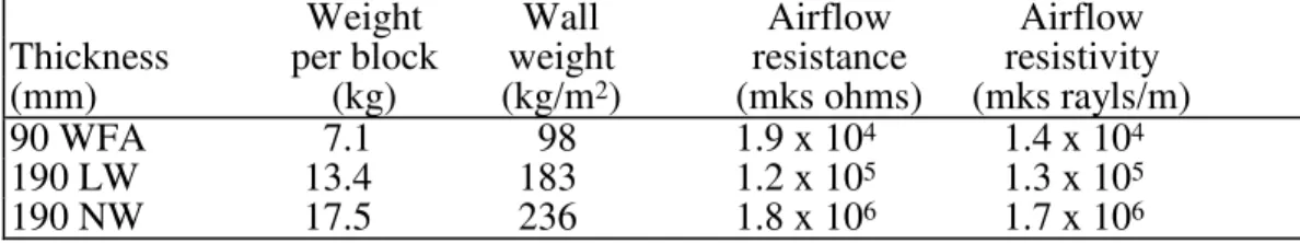
Two types of blocks were used in these measurements. One was a solid, 9 cm thick block manufactured using a coarse wood fiber aggregate (WFA). These blocks are significantly lighter than conventional blocks and are quite porous. The second type was a hollow core (50% solid), 19 cm thick, lightweight (LW) block. Table 1 gives some physical data including airflow resistance. Because they are referred to later, data for the normal weight (NW) blocks from reference 1 are included in the table. Airflow resistance was measured in accordance with ASTM C5228. For the hollow blocks, the material resistivity was calculated from the airflow resistance value taking account of flow through the block faces and webs.
Table 1: Physical data for the concrete blocks used in the measurements. The wall weight is for a bare wall with no attachments. The normal weight (NW) blocks are those used in Ref. 1.
Weight Wall Airflow Airflow
Thickness per block weight resistance resistivity
(mm) (kg) (kg/m2) (mks ohms) (mks rayls/m)
90 WFA 7.1 98 1.9 x 10⁴ 1.4 x 10⁴
190 LW 13.4 183 1.2 x 10⁵ 1.3 x 10⁵
190 NW 17.5 236 1.8 x 10⁶ 1.7 x 10⁶
The wood fiber aggregate blocks were laid in a running bond pattern. The lightweight blocks were laid in a stack bond pattern. On every second course, wire trusses were embedded in the mortar to give horizontal reinforcement.
B. Methods of attaching drywall
13 mm drywall was attached to the blocks in different ways. It was screwed on directly, or supported on 13 mm resilient metal channels, 40 mm steel studs or 65 mm steel studs. The stud systems had top and bottom tracks and were not in contact with the blocks. This resulted in airspaces being about 5 - 10 mm larger than the stud depth. Channels and studs were formed from 0.5 mm thick
galvanized sheet metal and were installed 600 mm apart. Figure 1 shows cross-sections and dimensions of the channels and the studs. For measurements with the wood fiber aggregate blocks, the drywall weighed 8.8 kg/m2. For the lightweight block series, it weighed 7.1 kg/m2.
(a) (c) 30 40 (b) 65 30 13 65 40
Figure 1: Cross-sections of the furring and studs used to support drywall. (a) 13 mm resilient metal channels, (b) 40 mm steel studs, (c) 65 mm steel studs.
C. Sound-absorbing materials
The sound-absorbing materials used in the wall systems are described in Table 2. The airflow resistivity of these sound-absorbing materials was not measured but representative values are included in the table.
Table 2: Sound absorbing material used in cavities. CGC - Canadian Gypsum Corporation; FC - Fiberglas Canada.
Airflow
Thickness Surface Weight resistivity
Type (mm) (kg/m2) (mks rayls/m)
unfaced duct wrap 25 0.3 5000
CGC Thermafiber 38 2.3 20000
FC R8 65 0.8 5000
II. DESCRIPTION OF MEASUREMENT FACILITIES AND PROCEDURES
Measurements were made in the sound transmission loss suite at the National Research Council Canada in accordance with ASTM E909. For wall transmission loss measurements, the source room has a volume of 65 m3 and the receiving room has a volume of 250 m3. Wall specimens measure 2.44 x 3.05 m and are
constructed on a steel, wheeled frame lined with wood. The frame fits between the rooms and is isolated from both. Each room has fixed and rotating diffusers and four corner-mounted loudspeaker systems fed with independent, pseudo-random noise sources. To measure transmission loss, white noise is fed to the loudspeakers in the source room. Pink noise is used to measure decays in the receiving room. Electret condenser microphones sample the sound fields at nine positions in the central volume of each room. Measurements are controlled by a computer system interfaced to a Norwegian Electronics 830 real time analyzer and cover the one-third octave band frequencies from 63 to 6300 hertz.
III. RESULTS FOR WOOD FIBER AGGREGATE BLOCKS
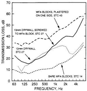
The bare wood fiber aggregate (WFA) block result in Fig. 2 makes it clear that sound passes easily through the porous block; the sound transmission loss is much less than expected for a wall of this weight.
Figure 2: Result for bare wood fiber aggregate (WFA) blocks, for WFA blocks with a single layer of 13 mm drywall screwed directly to them, and for plastered WFA blocks. A result for a single layer of drywall mounted on 13 mm resilient metal channels on 90 mm wood studs is included for comparison.
Figure 2 also shows that a sheet of 13 mm drywall screwed to one face of the block may provide an effective air seal, but the sound transmission class for the system is the same as that for the drywall on its own. To illustrate this, Fig.2 includes a result for a single layer of drywall mounted on 13 mm resilient
channels attached to 90 mm wood studs. With the drywall screwed directly to the block, the block weight begins to contribute to the sound transmission loss at frequencies below about 160 Hz, where transmission loss values increase. Above about 800 Hz, sound transmission loss increases relative to the result for the drywall, probably because of the block porosity. These data show that the drywall
is free to vibrate fairly independently and behaves, for the most part, as though the blocks were not there.
To improve the result for the bare block, one face must be sealed with plaster or a similar material. Figure 2 shows the transmission loss that resulted when one surface of the block wall was sealed using a layer of plaster about 2 mm thick; there was no added drywall in this case. The full benefit of the block weight is obtained and an STC of 43 results. The plaster added a mass of about 3.5 kg/m2 to the weight of the wood fiber aggregate block wall.
A. 13 mm Drywall on 40 mm steel studs
Figure 3 shows the result for the case where a layer of 13 mm drywall was screwed directly to one face of the blocks and on the second face a second layer was mounted on 40 mm steel studs. Data are given for the cavity empty and filled with sound-absorbing material. The STC rating is about the same as for two layers of drywall with a 140 mm-deep cavity between them. The addition of sound-absorbing material in the cavity increased sound transmission loss values at all frequencies but the block mass still contributes very little to the wall sound transmission loss.
Figure 3: Wood fiber aggregate (WFA) blocks with 13 mm drywall screwed directly to one face. On the second face, 13 mm drywall is mounted on 40 mm steel studs. Data are for two cases: with and without mineral fiber batts in the 40 mm cavity.
B. Plastered wood fiber aggregate blocks with added drywall
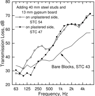
Once the wood fiber aggregate blocks were plastered, adding drywall on steel studs gave much better STC ratings than those obtained for the same materials applied to the unplastered block. Figure 5 shows the results for 13 mm drywall supported on 40 mm studs first on the unplastered side and then on the plastered side of the wall. The two curves and the STC ratings are different. The plaster defines the boundary of the cavity, so for drywall on the plastered side, the cavity depth is about 45 mm, the distance from the rear face of the drywall to the plaster. For drywall on the unplastered face, the porosity of the block increases the
effective cavity depth to about 135 mm, the distance from the rear face of the drywall, through the porous block to the plaster. The deeper air-cavity gives a lower crossover frequency and improvements in transmission loss relative to the bare block begin at lower frequency.
63 125 250 500 1k 2k 4k 20 30 40 50 60 70 80 Bare Blocks, STC 43
Adding 40 mm steel studs and 13 mm gypsum board on unplastered side, STC 54 on plastered side, STC 47 T ransm issi on Loss, dB Frequency, Hz
Figure 4: Effects of adding 13 mm drywall on 40 mm studs to the plastered face and to the unplastered face of the wood fiber aggregate (WFA) block wall. The result for the bare, plastered blocks is included for reference.
The dip around 450 Hz in the dotted curve was influenced by the softness of the added plaster layer. The result shown was measured after the plaster had cured. When the plaster was fresh, the transmission loss values at the dip were about 4 dB higher. It is not obvious what physical mechanism this resonance is associated with.
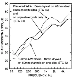
Reference 1 gave transmission losses for a system similar to that for the dotted curve shown in Figure 5 but using 190 mm normal-weight concrete blocks described in Table 1. Figure 6 compares the results, and it can be seen that the heavier wall gave a slightly lower STC rating and lower transmission loss values at low frequencies. Because of the larger effective air-gap, the mass-air-mass resonance occurs at a lower frequency for the wood fiber aggregate block wall and it gives better sound insulation at low frequencies than does the heavier wall.
Figure5: Results for the 90 mm wood fiber aggregate (WFA) blocks with 13 mm drywall on 40 mm steel studs on the unplastered face only and on both faces. A 190 mm normal weight (NW) system from Ref. 1 is shown for comparison. The NW system has 16 mm drywall attached on one side with 25 ga. steel Z-bars that support the drywall 50 mm from the block surface.
Figure 5 also shows results for the wall with 13 mm drywall mounted on 40 mm steel sutds on both faces of the plastered wood fiber aggregate blocks. This system had an STC one point higher than the wall with the drywall on the plastered side only. There is, however, a general decrease in transmission loss at frequencies below about 250 Hz. This is due to the mass-air-mass resonance associated with the smaller cavity on the plastered side of the block. Adding sound-absorbing material to the cavity on the plastered side of the wood fiber aggregate blocks would improve the sound insulation. Just how much is estimated later.
IV. RESULTS FOR LIGHTWEIGHT CONCRETE BLOCKS A. Unplastered
1. 13 mm Drywall on resilient metal channels and 40 mm steel studs
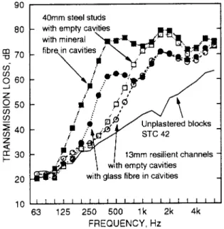
Figure 6: Transmission loss data for lightweight (LW) 190 mm blocks with 13 mm drywall mounted on both sides on 13 mm resilient metal channels and 40 mm steel studs.
Each side of the unplastered lightweight (LW) block wall was finished with 13 mm drywall mounted on resilient metal channels or 40 mm steel studs. The cavities were empty or had sound-absorbing material in them. Figure 6 shows measured transmission losses; the result for the bare block is included for comparison. The results resemble those in Ref. 1 more than those for the wood fiber aggregate blocks do. There are significant increases in transmission loss due to the cavity behind the added drywall. As the cavity depth increases or as sound-absorbing material is added, the improvements in transmission loss begin at lower frequencies. There is, however, no sign of any significant decrease in
transmission loss that can be associated with a mass-air-mass resonance, nor any clear crossover frequency. One explanation for this is that the block airflow resistance or porosity provides a loss mechanism that reduces the depth of the mass-air-mass resonance. This mechanism, whatever it is, does not change the position of the mass-air-mass resonance. This contrasts with the action of the added glass and mineral fiber which cause the mass-air-mass resonance to move but do not influence the depth of the resonance.
B. Plastered lightweight blocks 1. Effect of plaster on bare blocks
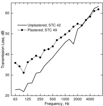
63 125 250 500 1000 2000 4000 20 30 40 50 60 Unplastered, STC 42 Plastered, STC 49 T ran sm is si on Lo ss, dB Frequency, Hz
Figure 7: Effect of plastering one face of lightweight blocks.
Plastering one face of the 190 mm lightweight blocks produced the change in transmission lossshown in Fig. 7. Improvement is most marked at low
frequencies and decreases as frequency increases. The dip in the transmission loss curve seen in the bare block result at 1.6 kHz disappeared after plastering. No explanation for this dip has been found. A sound leak or other construction flaw was suspected, but none could be discovered.
2. Plastered blocks - 13 mm Drywall on steel studs
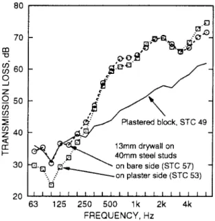
Figure 8: Effect of adding 13 mm drywall on 40 mm steel studs to each side of lightweight plastered blocks.
Figure 8 shows transmission loss results for drywall attached on 40 mm steel studs on the plastered side of the block wall and on the unplastered side. In the latter case, the detrimental effects of the mass-air-mass resonance are gone, presumably because of the losses associated with block porosity. Similar effects were seen for 65 mm steel studs. Adding sound-absorbing material in the cavity on each side gave similar results except that the crossover frequency moved to a lower frequency; the mass-air-mass resonance was still present when drywall was added to the plastered face and not evident when it was added to the unplastered face.
V. DISCUSSION
A. Effect of plaster on bare blocks
It is common experience that the more porous the block, the more important it is to seal one face with paint or plaster when no other finish is to be added.
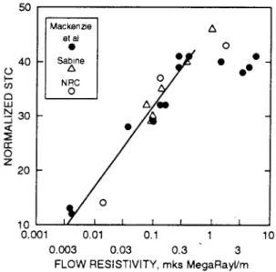
References 5 and 6 showed relationships between airflow resistance and transmission loss. R.K. Mackenzie kindly supplied the data from the work in reference 5 and the results were converted to STC and airflow resistivity, in mks rayl/m. The data in reference 6 were also converted to the same units. The data include results for 9, 14, and 19 cm blocks both dense and lightweight. The different block weights would give different STC ratings even if all were correctly sealed. To compensate for the differences in weight, it was assumed that STC would increase approximately as 20 log M, where M is the surface mass of the
= STCm - 20 log (M/100). Both sets of published data together with the three values from the present work are plotted in Figure 9 in this form.
Figure 9: Relationship between normalized STC and airflow resistivity for unsealed concrete blocks. The solid line is a linear fit to the data below 5 x 10⁵ rayl/m. The agreement from research work spanning a thirty year period is satisfying. This figure can be used to estimate what change in STC will occur when blocks are sealed.
B. Delta Tl curves
In Ref. 1, the effects of adding drywall to normal weight block walls were most clearly seen by looking at transmission loss differences relative to the single-withe block case. The difference spectrum is called the ∆TL curve. This approach is adopted again in what follows.
Figure 10: ∆TL curves for 13 mm resilient metal channels. The solid curve is from the present work and applies to the unplastered lightweight (LW) blocks and 13 mm drywall. The dotted curve is from Ref. 1 and applies to normal weight (NW) blocks and 16 mm drywall.
Figure 10 shows the ∆TL curve for 13 mm drywall on 13 mm resilient metal channels attached to the lightweight blocks. For comparison, the ∆TL curve for 16 mm drywall on resilient metal channels from reference (1) is included. The absence of a mass-air-mass resonance with the lightweight blocks is clear. For the normal weight blocks in reference (1), adding drywall on resilient channels on both sides caused a drop in STC from 50 to 49. For these lightweight blocks, the same construction increased the STC rating from 42 to 47. So, the overall performance of the lightweight blocks is, in this case, about as good as the normal-weight blocks.
Figure 11: DTL curves for wood fiber aggregate (WFA), lightweight (LW), and normal weight (NW) blocks. The LW and WFA blocks were plastered; the curves apply to 40 mm studs and 13 mm drywall attached on the plastered side. The NW blocks were not plastered; the curve applies to 50 mm Z-bars and 16 mm drywall.
The effect of block porosity is perhaps clearer in Figures 11 and 12. Figure 11 shows ∆TL for 13 mm drywall supported on 40 mm steel studs for the three types of block. The lightweight and the wood fiber aggregate blocks were plastered and the studs and drywall were attached on the plastered side. Although the steel studs were 40 mm deep, the drywall was actually supported at a distance of about 45 mm from the block surface because of small gaps between the studs and the blocks. The ∆TL curve for 50 mm Z-bars from reference (1) is included for comparison. The three curves show similar behavior and clear mass-air-mass resonances around 125 Hz.
Figure 12: DTL curves for 40 mm steel studs and 13 mm drywall on lightweight (LW) and wood fiber aggregate blocks (WFA). The WFA curve and one of the LW curves apply to plastered blocks with the drywall applied on the unplastered side. The second LW curve applies to unplastered blocks.
Figure 12 is only for the lightweight and wood fiber aggregate blocks. In this case, the 40 mm steel studs were on the unplastered side of the blocks. The ∆TL curve for the wood fiber aggregate blocks clearly shows the benefits of the increase in effective air cavity but there is still a mass-air-mass resonance around 80 Hz. The unplastered lightweight blocks do not show any strong mass-air-mass resonance. Nor do the plastered lightweight blocks, but the added plaster on the second face strongly influences the shape of the ∆TL curve. Since no explanation of the physical processes involved has been given, the reasons for the differences are not explained. Similar effects were seen for 65 mm steel studs. The
lightweight block porosity seems to add a loss mechanism that almost eliminates negative ∆TL at the low frequencies but there is still an increase in transmission loss at higher frequencies above where the crossover frequency could be expected. Table 5 lists the ∆TL values for each combination tested. In all cases where a cross-over frequency is evident, it moves to lower frequencies as the air gap is larger.
Figure 13: Sound transmission for the two block types used in this study and that in Ref. 1. The result for the wood fiber aggregate (WFA) blocks is a calculated result for 13 mm drywall on 40 mm steel studs on each side of the plastered blocks. The cavity on the plastered side is filled with sound-absorbing material. The result for the lightweight (LW) block is for the same system but is a measured result. The result for the 190 mm normal weight (NW) blocks from Ref. 1 is for 16 mm drywall on 50 mm Z-bars on each side of the block. The cavity is filled on one side with sound-absorbing material.
Above it was stated that the sound transmission losses for the wood fiber
aggregate wall finished on both sides with drywall on 40 mm steel studs could be improved if sound-absorbing material were added to the cavity on the plastered side. The ∆TL values for 40 mm steel studs and sound-absorbing material applied over plaster in Table 5 were used to estimate the result for the construction. The prediction is compared in Figure 13 with that for measured data for similar systems using the lightweight blocks in this paper (wall number 92 in Table 4) and the normal weight blocks from Ref. 1. The normal weight block system used 50 mm Z-bars and 16 mm drywall. The predicted transmission loss values are most uncertain at frequencies above about 500 Hz but, in this case, these values have no effect on the STC rating which is 63.
Figure14: Measured versus calculated crossover frequency for the wood fiber aggregate (WFA) and lightweight (LW) block wall systems. The solid line is the locus where both are equal.
To compare the position of the measured crossover frequency with that calculated from Eq. 1, one has to know the cavity depth and the influence of
sound-absorbing materials. For some value of block airflow resistance, because air penetrates the block surface, the effective depth of the cavity behind the drywall is increased somewhat. These measurements, however, showed that there was no such increase. The cavity depth was assigned as follows: for the lightweight blocks-- the distance from the rear of the drywall to the surface of the blocks (plastered or unplastered); for the wood fiber aggregate blocks-- the distance from the rear of the drywall to the surface of the plaster, including the block thickness if necessary. The measurements also showed that the block porosity did not move the mass-air-mass resonance to a lower frequency in the same way that the addition of glass or mineral fiber does. Thus, no allowance was made for block porosity when using Eq. 1.
In some cases, the ∆TL curve approaches zero gradually and the position of the crossover frequency is somewhat uncertain. In such cases, its position was estimated by extending the ∆TL curve back to zero from the steeply rising part. For example, the solid line in Fig. 12 has an estimated crossover frequency about 250 Hz while the dashed line has a crossover frequency at 200 Hz. The positive
∆TL values below these frequencies were considered to be random fluctuations associated with the uncertainties in the testing process.
Calculated and measured values of crossover frequency are shown in Fig. 14. With the exception of three or four points, the agreement is good.
VI. CONCLUSIONS
The wood fiber aggregate blocks are too porous to provide good sound transmission loss without being correctly sealed. The data show that sealing blocks correctly requires the use of plaster or some other material that adheres completely to the block. Sheet materials attached at points by screws or the like will not be adequate. This result has implications for other situations. For
example, if a normal weight block wall is poorly constructed with sound leaks due to faulty mortar, applying drywall to one face with screws or on furring strips will not bring the sound transmission losses up to the values for a properly sealed block. Filling cavities with sound-absorbing material might help to reduce the detrimental effects of a poorly constructed block wall, but sealing the blocks properly is a more certain procedure.
The porosity of the wood fiber aggregate blocks increases the effective cavity depth if the blocks are plastered, but there are still marked negative ∆TL values associated with the mass-air-mass resonance. There is thus no significant absorption added to the cavity by the blocks.
The porosity of the wood fiber aggregate blocks can be turned to advantage if they are completely sealed on one face, either during manufacture or on-site. Then, despite their comparatively low weight, correct design procedures allow the construction of block wall systems that provide high STC ratings.
Sound transmission loss for the lightweight block walls is improved when one face is sealed with plaster. Some loss mechanism associated with the porosity makes the depth of the mass-air-mass resonance negligible while the improved transmission loss above the crossover frequency is still obtained. The loss mechanism does not, however, seem to change the location of the mass-air-mass resonance. Walls constructed with these blocks can give transmission loss values about as good as those for heavier walls.
The work presented here and that in Reference 1 covers a large range in airflow resistance. At one extreme, the block was extremely porous and presented little impediment to the passage of sound. At the other, the blocks had such high airflow resistance that sealing caused no change in transmission loss. Despite this range and the differences in surface mass, it is evident from Fig. 13 that high sound transmission losses can be obtained with very lightweight blocks. There are many variables to be considered when designing block walls, and it would be preferable to have a better understanding of the processes that take place in the sound-absorbing material and in the porous blocks. It is possible that there is some block airflow resistance that would allow construction of a wall giving maximum transmission lossfor a given cavity airspace and with a minimum degree of complexity in the construction. It will, however, require more research to determine if this is so and what is practical. One thing is certain: having airflow resistance data easily available when blocks are to be used would make it easier to decide how to finish them.
1 and Side 2 have the following meaning: G13 13 mm drywall; RC13 13 mm resilient metal channels; SS40 40 mm steel studs; SS65 -65 mm steel studs; GFB - glass or mineral fiber batts; PLA - plaster (the number following gives the thickness in mm).
Wall # Side 1 Side 2 STC 63 80 100 125 160 200 250 315 400 500 630 800 1000 125 0 160 0 200 0 250 0 315 0 400 0 500 0 630 0 041 Bare Bare 14 10 8 7 8 6 7 9 10 10 10 11 11 13 15 16 17 19 21 24 28 32 042 G13 Bare 29 23 19 17 16 15 16 19 20 21 23 27 30 32 35 38 40 40 39 43 50 56 043 G13 SS40_GFB38_ G13 47 24 20 22 24 28 31 36 40 43 48 53 59 63 67 69 68 66 64 67 70 72 044 G13 SS40_G13 43 21 17 18 22 24 27 32 35 38 42 46 51 55 60 63 64 58 56 63 68 70 045 Bare SS40_G13 31 13 11 12 14 13 15 18 22 26 30 33 36 39 43 46 47 45 44 50 54 62 046 G13_SS40 SS40_G13 43 10 10 12 20 22 28 32 35 39 44 48 54 57 63 66 66 61 59 66 71 72 049 PLA2 SS40_G13 54 28 28 32 37 40 45 47 48 46 46 48 53 57 60 63 64 63 62 65 69 71 050 G13_SS40_ PLA2 SS40_G13 55 22 22 24 31 36 44 47 48 50 53 57 65 69 72 73 71 69 66 69 74 78 051 G13_SS40_ PLA2 Bare 47 31 28 26 28 27 32 37 39 42 45 48 55 59 63 64 64 64 63 65 68 71 052 PLA2 Bare 43 34 33 31 34 33 34 36 38 38 37 38 41 43 46 47 48 51 53 55 57 58
and Side 2 have the following meaning: G13 - 13 mm drywall; RC13 - 13 mm resilient metal channels; SS40 - 40 mm steel studs; SS65 - 65 mm steel studs; GFB - glass or mineral fiber batts; PLA - plaster (the number following gives the thickness in mm). Wall # Side 1 Side 2 STC 63 80 100 125 160 200 250 315 400 500 630 800 1000 1250 1600 2000 2500 3150 4000 5000 6300 073 bare bare 42 23 23 22 26 26 31 31 34 37 39 41 43 46 47 45 52 54 57 59 62 63 074 G13 bare 46 26 25 24 29 30 35 36 38 39 41 45 49 53 55 56 60 58 58 59 63 65 075 G13 RC13_G13 49 28 26 25 31 33 37 37 40 42 45 50 55 59 64 68 68 65 63 64 67 70 076 bare RC13_G13 45 22 21 21 27 28 32 32 36 38 41 46 52 57 61 63 65 63 62 62 66 68 078 G13_RC13 RC13_G13 47 22 22 22 28 31 34 34 37 40 44 51 58 61 67 71 70 68 67 67 70 73 079 G13_RC13_GFB13 RC13_G13 51 22 22 23 27 30 34 38 45 51 56 60 59 61 67 71 70 68 67 68 71 72 080 G13_RC13_GFB13 RC13_GFB13_G13 49 20 21 20 26 28 35 42 54 61 62 61 59 61 66 71 70 69 68 69 72 74 081 G13_RC13_GFB13 bare 48 21 21 21 26 27 33 37 43 49 52 55 57 60 64 66 65 63 62 63 67 70 082 G13_SS40 bare 46 20 21 21 26 27 31 33 37 41 46 51 57 61 66 68 69 66 65 68 72 73 083 G13_SS40 SS40_G13 47 20 21 20 25 28 32 34 37 43 50 57 66 71 73 78 78 74 70 72 76 73 084 G13_SS40 SS40_GFB38_G13 53 20 21 22 29 35 42 47 55 64 70 73 73 73 74 79 79 75 72 73 77 76 086 G13_GFB38_SS40 SS40_GFB38_G13 56 20 21 24 32 41 50 57 67 75 75 77 74 73 75 79 79 76 72 72 76 75 087 bare SS40_GFB38_G13 52 20 21 21 28 34 41 45 52 58 61 64 65 66 68 70 71 69 67 68 71 72 089 PLA3 SS40_GFB38_G13 63 34 36 32 39 42 47 51 57 61 63 65 65 66 68 70 70 68 66 67 70 72 090 PLA3 SS40_G13 57 34 35 30 37 36 40 43 49 56 60 63 64 64 67 69 70 68 65 67 70 72 091 G13_SS40_PLA3 SS40_G13 53 29 28 24 30 32 37 43 49 61 70 73 74 73 74 78 78 75 71 72 76 79 092 G13_GFB38_SS40_PLA3 SS40_G13 61 27 29 29 37 40 46 54 65 73 76 77 74 73 74 79 79 76 72 73 77 79 093 G13_GFB38_SS40_PLA3 SS40_GFB38_G13 64 28 29 29 40 46 54 62 72 77 78 78 75 74 75 80 81 78 74 75 77 79 103 G13_GFB38_SS40_PLA3 bare 62 29 30 29 38 43 47 51 58 61 62 62 61 64 70 72 72 69 67 69 73 76 104 G13_SS40_PLA3 bare 53 30 29 24 29 32 37 41 47 55 59 61 61 63 68 70 70 67 66 68 73 75 105 G13_SS65_PLA3 bare 56 27 29 26 33 35 40 44 51 57 60 63 65 68 70 73 73 70 70 73 78 80 106 G13_GFB65_SS65_PLA3 bare 65 29 33 34 41 45 49 53 60 63 65 66 67 69 72 74 75 73 71 74 79 83 107 G13_GFB65_SS65_PLA3 SS65_GFB65_G13 69 30 35 36 45 51 58 64 76 80 84 84 84 82 82 85 86 83 76 79 86 84 108 G13_GFB65_SS65_PLA3 SS65_G13 64 29 33 34 40 46 51 58 68 77 79 82 82 81 81 84 85 81 74 77 85 85 110 G13_SS65_PLA3 SS65_G13 55 23 26 24 31 35 42 46 53 66 74 78 82 81 81 83 84 80 74 77 86 84 111 PLA3 SS65_G13 58 36 35 31 36 37 41 45 50 57 61 64 66 68 69 71 72 70 68 70 75 78 112 PLA3 SS65_GFB65_G13 64 37 36 33 40 44 49 53 60 63 66 69 69 70 71 72 74 74 71 72 77 79 113 PLA3 bare 49 36 34 31 36 38 39 39 42 43 44 47 48 50 51 53 55 54 57 58 61 62
Method of Frequency, Hz
Attachment 63 80 100 125 160 200 250 315 400 500 630 800 1000 1250 1600 2000 2500 3150 4000 5000 6300 190 mm Lightweight blocks unplastered
Direct 3.1 1.8 2.5 3.1 4.0 4.5 4.8 4.0 2.7 2.2 3.5 5.5 7.4 7.8 11.2 7.4 4.7 1.6 0.0 0.3 1.5 RC13 -0.5 -0.7 0.1 0.9 1.9 1.4 1.2 1.4 1.9 3.2 4.9 5.8 6.8 9.2 12.2 8.7 7.1 4.9 3.9 3.9 4.0 GFB13_RC13 -0.8 -0.9 0.2 0.0 1.3 2.1 5.3 9.2 12.7 13.5 12.7 9.4 8.5 10.6 14.1 9.1 7.2 5.4 4.9 5.2 5.7 SS40 -1.6 -1.0 -0.3 0.2 1.1 0.9 1.6 2.3 4.6 7.5 8.9 11.1 11.7 12.8 16.0 12.5 9.7 6.7 6.9 7.6 6.6 SS40_GFB40 -1.2 -1.1 0.4 2.8 7.6 10.1 13.5 17.7 20.9 21.6 20.7 17.4 15.1 14.0 17.6 13.8 11.9 8.2 6.7 6.8 5.8
190mm lightweight blocks, plastered on one side. Attachment on the bare block side
SS40 -1.6 -0.2 -0.1 0.0 -1.5 -0.3 3.4 4.9 10.5 13.7 14.7 13.5 11.3 8.8 10.3 10.2 9.8 6.0 5.5 5.4 5.7 SS40_GFB40 -1.3 0.3 0.3 2.3 3.8 7.1 11.9 14.5 16.9 17.6 17.2 15.3 13.2 11.0 12.3 12.1 11.5 7.7 7.0 6.8 6.7 SS65 -1.3 -0.8 -0.7 -1.0 0.0 1.6 4.1 6.2 12.3 15.2 16.1 16.8 14.5 12.8 12.4 12.3 11.3 6.4 6.5 9.3 7.4 SS65_GFB65 1.1 1.7 2.3 4.2 6.4 9.3 12.7 17.1 19.0 20.5 19.7 18.8 16.2 14.8 15.0 15.0 14.8 9.6 9.3 11.2 9.2
190mm lightweight blocks, plastered on one side. Attachment on the plastered block side
SS40 -5.8 -6.4 -6.8 -6.9 -4.8 -2.6 0.7 3.0 8.8 12.5 12.1 11.7 11.2 12.0 12.2 11.4 10.0 7.1 7.9 9.0 9.9 SS40_GFB40 -6.9 -5.6 -1.8 1.3 4.7 7.1 11.6 15.7 17.3 16.3 14.2 11.4 10.3 11.1 12.7 12.4 11.4 8.4 8.3 8.6 9.3 SS65 -10.6 -7.1 -5.9 -3.9 -2.6 0.7 3.5 5.7 11.4 14.4 14.7 16.0 15.6 15.6 15.9 15.1 13.2 9.4 10.7 13.5 12.2 SS65_GFB65 -6.9 -1.7 3.0 4.3 7.7 9.4 13.2 17.3 19.1 19.0 17.6 16.5 14.9 14.6 15.8 15.3 13.3 8.8 10.0 12.7 10.9
Plastered 90 mm wood fiber aggregate blocks Attachment on the bare block side
SS40 -5.6 -5.5 0.8 3.2 7.3 10.4 11.0 10.2 8.0 8.8 10.6 12.1 13.5 14.0 16.6 15.6 12.2 8.5 9.8 12.0 13.8 Attachment on the plastered block side
1
"Sound transmission through concrete blocks with attached drywall". A.C.C. Warnock, JASA, 90, pp 1459 1463, September 1991
2
"The Tenth Sir Richard Fairey Memorial Lecture: Sound Transmission in Buildings", M. Heckl, JSV, 77, p165, 1981.
3
. L. Cremer, Zeitschrift fur Warmeschutz, Kalteschutz, Schallschutz, Brandschutz, 1-11. Isolation und Absorption durch Doppelwande. Ludwigshafen: Grunzeweig und Hartmann. 1980 4
. "Transmission loss of some masonry walls". B.G. Watters, JASA, 31, 7, p898, 1959 5
. "Effect of painting on sound transmission loss of lightweight concrete block partitions". H.J. Sabine, Noise Control, p6, Mar/Apr 1960.
6
. "Sound insulation of lightweight concrete". J.J Williamson and R.K. Mackenzie. BUILD International, July/August 1971, p244.
7
. "The effect of cement render upon the sound insulation of dry-lined concrete block wall", R. Mackenzie, B. Ma, R. Wilson, M. Stewart, Proc. Inst. of Acoustics, Vol. 10, Part 8, p21,(1988). 8
. ASTM C522, Standard Test Method for Airflow Resistance of Acoustical Materials. 9
. ASTM E90, Standard Test Method for Laboratory Measurement of Airborne Sound Transmission Loss of Building Partitions.