Publisher’s version / Version de l'éditeur:
Vous avez des questions? Nous pouvons vous aider. Pour communiquer directement avec un auteur, consultez la première page de la revue dans laquelle son article a été publié afin de trouver ses coordonnées. Si vous n’arrivez pas à les repérer, communiquez avec nous à [email protected].
Questions? Contact the NRC Publications Archive team at
[email protected]. If you wish to email the authors directly, please see the first page of the publication for their contact information.
https://publications-cnrc.canada.ca/fra/droits
L’accès à ce site Web et l’utilisation de son contenu sont assujettis aux conditions présentées dans le site LISEZ CES CONDITIONS ATTENTIVEMENT AVANT D’UTILISER CE SITE WEB.
The e-Way into the Four Dimensions of Cultural Heritage Congress
[Proceedings], 2003-04
READ THESE TERMS AND CONDITIONS CAREFULLY BEFORE USING THIS WEBSITE. https://nrc-publications.canada.ca/eng/copyright
NRC Publications Archive Record / Notice des Archives des publications du CNRC :
https://nrc-publications.canada.ca/eng/view/object/?id=d2282922-12b8-44b2-abe3-3cea63126d3a
https://publications-cnrc.canada.ca/fra/voir/objet/?id=d2282922-12b8-44b2-abe3-3cea63126d3a
NRC Publications Archive
Archives des publications du CNRC
This publication could be one of several versions: author’s original, accepted manuscript or the publisher’s version. / La version de cette publication peut être l’une des suivantes : la version prépublication de l’auteur, la version acceptée du manuscrit ou la version de l’éditeur.
Access and use of this website and the material on it are subject to the Terms and Conditions set forth at
Active 3D Sensing
Beraldin, Jean-Angelo; Blais, François; Cournoyer, Luc; Godin, Guy; Rioux,
Marc; Taylor, John
National Research Council Canada Institute for Information Technology Conseil national de recherches Canada Institut de technologie de l'information
Active 3D Sensing *
Beraldin, J.-A., Blais, F., Cournoyer, L., Godin, G., Rioux, M., Taylor, J.
April 2003
* published in The e-Way into the Four Dimensions of Cultural Heritage Congress. April 8-12, 2003. Vienna, Austria. NRC 46495.
Copyright 2003 by
National Research Council of Canada
Permission is granted to quote short excerpts and to reproduce figures and tables from this report, provided that the source of such material is fully acknowledged.
Active 3D sensing for Heritage Applications
J-A. Beraldin, F. Blais, L. Cournoyer, G. Godin, M. Rioux and J. Taylor Institute for Information Technology
National Research Council Canada Ottawa, Ontario, Canada, K1A 0R6 e-mail: [email protected]
Abstract
Active three-dimensional vision is concerned with extracting information from the geometry and the texture of the visible surfaces in a scene, reasoning about the data and finally, communicating the results. In order to take full advantage of these vision systems, one must understand not only their advantages but also their limitations. This paper covers some issues that must be addressed before embarking in a 3D scanning project.
1 Introduction
In the last twenty years, many advances have been made in the field of solid-state electronics, photonics, computer vision and computer graphics. Non-contact three-dimensional (3D) measurement techniques like those based on structured light and passive stereo are examples of fields that have benefited from all of these
developments (Handbook 1999). These non-contact measurement techniques have found widespread use in heritage, environment modeling, virtual reality, and many industrial fields. Figure 1 shows a classification of non-contact measurement strategies that rely on light waves. In the case of passive techniques (that use ambient light), only visible features with discernable texture gradients like on intensity edges are measured. Laser-based systems are used to structure the environment in order to acquire dense range maps from visible surfaces that are rather featureless to the naked eye or a video camera. Hence, the 3D information becomes relatively insensitive to background illumination and surface texture. This paper reviews the basic principles that underline the majority of active 3D vision systems. Some pointers are presented in order for the reader to become more critical when picking a 3D vision system. The target application is in the context of cultural heritage (Godin 2002). Concluding remarks appear at the end of the paper.
2 Representations of three-dimensional surfaces
The simplest way of representing and storing surface coordinates of a scene is with the use of a depth map. A depth map is like a grey scale image generated by a 2D camera except that the z information replaces the intensity information. If the elements of the image are organized so that for a given 3D coordinate all the coordinates surrounding it are physically neighbours of that coordinate, then we have an organized point cloud. If a grey scale value is assigned to each surface element (e.g. using a triangular patch) according to their slope angles, then this method provides a way to artificially shade an image in order to highlight surface details.
3 Three-dimensional sensing
• Triangulation
Triangles are the basis of many measurement techniques, from basic geodesic measurements performed in ancient Greece to more modern laser-based 3D cameras. The Greek philosopher Thales (6th century BC) has been credited with the discovery of five theorems in geometry. Two of which are used to solve the triangulation equations in a triangulation-based range camera: opposite angles of intersecting straight lines and the cosines law. Triangulation is used in applications requiring an operating range that is less than 10 meters. For ranges between 2 m and 10 m, there are a limited number of triangulation-based sensors available commercially. The geometrical
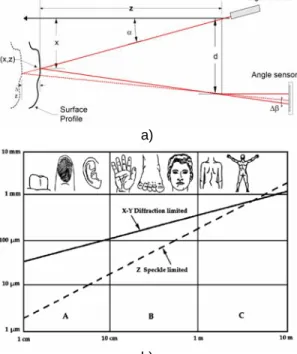
principle of optical triangulation is shown in Fig. 2a. Knowing two angles (α and ∆β) of a triangle relative to its base (baseline d) determines the shape of the triangle. For an incremental change of distance, ∆z, one measures the change ∆β (assuming α constant) using the theorem of opposite angles. The angle sensor shown on that figure is in fact a solid-state image sensor. To measure a profile, one needs to scan the spot.
To show the limitations of triangulation, people approximate the measurement uncertainty of the error in z by the law of propagation of errors. One finds, that the measurement uncertainty in z is inversely proportional to both the camera baseline and the effective focal length of the lens, but directly proportional to the square of the distance. Unfortunately, fo and d cannot be made as large as desired. The baseline d is limited mainly by the mechanical structure of the optical set-up (stability of the whole system decreases as d increases) and by shadow effects (self occlusion problems increase with d). Rioux 1994 presents an innovative approach to triangulation-based range imaging that allows very large fields of view without compromising the performance of the system. In order to acquire a full 3D image, one has to either move the scanner or use another technique that yields full field 3D measurements. Galvanometer-based systems use two mirrors to raster scan a scene. Depending on the application, line scanners can be mounted on rotation, translation stages or coordinate measuring machines (CMM). Finally multi-line laser projection and coded pattern projection systems are also used for full field 3D cameras (Handbook 1999). Moiré effect is another 3D technique.
• Time delay
A fundamental property of light waves is their velocity of propagation. In a given medium, light waves travel with a finite and constant velocity. Thus the measurement of time delays created by light traveling in a medium from a source to a reflective target surface and back to the source (round trip) offers a very convenient way to evaluate distance. With an approximated speed of light of 3×10⁸
m/sec, then, 3.33 nanoseconds correspond to about 1 meter. Interesting enough, 3D systems based on time delay measurement are used either for very small fields of view (< 10 mm) or very large ones (> 10 m). For ranges between 0.2 m and 10 m, there is a limited number of this type of sensor available commercially. Long-range sensors (range exceeding 10 meters) are usually based on the time-of-flight (TOF) technology (also known as laser radar or lidar for short). The camera to object distance (z) is measured by sending a relatively short impulse of light on a reflective surface and measuring the round trip, τ, z=c*τ/2. If one wants a resolution of 1 mm then a time delay of about 3.33 picoseconds will have to be measured. Most commercial systems provide a resolution of about 10 mm to 100 mm. Other systems based on continuous wave (CW) modulation get around the measurement of short pulses by modulating the power of the laser beam. Again the modulated signal is projected onto a surface, the scattered light is collected and a circuit measures the phase difference between the two waveforms and hence a time delay. For instance, with a frequency of 10MHz and a phase resolution of 0.01 degree (not too difficult with standard electronics), the
resolution in z is about 0.5 mm. Because the returned wave cannot be associated with a specific part of the original signal, it is not possible to derive the absolute distance information from a simple CW method. This is known as the ambiguity interval. To get around the inconvenience of a range ambiguity interval, one can use multiple frequency waveforms.
• Interferometric
The high coherence of laser light is very helpful in measurement involving interference of light beams. If a light beam is divided into two parts (reference and measuring) that travel different paths, when the beams are combined together interference fringes are produced. Such devices are called laser interferometers. Very small
displacements (in the order of a fraction of wavelengths) can be detected (using coherent detection), and longer distances can be also measured with low measurement uncertainty (Handbook 1999).
4 Performance evaluation of laser-based triangulation sensors
• Laser beam propagation
Optical triangulation resolution is limited by the diffraction of the laser light. Even in the best emitting conditions (single mode) the laser light does not maintain collimation with distance. In fact, the smaller the laser beam, the bigger is the divergence produced by diffraction. Fig. 2b illustrates that constraint. The solid line shows the relationship between the X and Y axes resolution (direction perpendicular to the laser projection) and the physical dimensions of the object to be scanned. Figure 3 presents results obtained with our laser scanner.
• Measurement uncertainty
Diffraction limits impose a constraint on the resolving power along the X and Y-axes as described above, but along the range axis (Z) one could expect a continuous improvement as the amount of laser power is increased. Unfortunately this is not the case; indeed the coherence of the laser light produces damaging interference effects that limit the resolving power of a position sensor Fig. 2b. This is known as the speckle effect.
• Calibration
The calibration of any range camera is concerned with the extraction of the internal parameters of the range camera when a mathematical model exists (focal length, lens distortions, scanning parameters, etc.) or with a mapping of the distortions in a look-up table when some elements cannot be modelled very well. After this phase, the range measurements are available in a rectangular co-ordinate system. After the calibration process, the accuracy, repeatability and measurement uncertainties of the range camera can be determined. This is the
verification stage. 5 Conclusion
We reviewed some of the basic principles behind 3D range cameras: from simple trigonometric relations to parameters involved in the digitizing of a 3D object. The purpose of measuring 3D objects and sites could be for documentation, inspection or visualisation and possibly all of them. The potential of active 3D vision for
applications in heritage or as an input to virtualized reality environments was discussed. Real world acquisition and modeling is now possible. Technological advances are such that difficulties are more of a logistical nature than technology per se. Additional information on commercial 3D digitizing systems is available on the following web site: http://www.vit.iit.nrc.ca/Pages_Html/English/Links.html
References
Godin, G. et al. 2002. Active Optical 3D Imaging for Heritage Applications. IEEE CG&A 22(5):24-36.
Handbook of Computer Vision and Applications. 1999. Volume 1: Sensors and Imaging, Chap. 17-21 Editors B. Jähne, H. Haußecker and P. Geißler, Academic Press, San Diego.
Rioux, M. 1994. Digital 3-D imaging: theory and applications. SPIE Proceedings, Videometrics III, International Symposium on Photonic and Sensors and Controls for Commercial Applications, Boston, MA. October 31 - November 4, Vol. 2350, pp. 2-15.
Figures
Figure 1. Classification of non-contact 3D surface measurement techniques based on light waves.
a)
b)
Figure 2. Principle of active triangulation: a) a triangulation-based laser probe, b) physical limits of 3D optical measurements based on laser projection and triangulation.
Figure 3 Shaded 3D model of a fragile cuneiform tablets can be interactively examined and the writing “unwrapped” for study. The X-Y resolution is 0.05 mm and Z uncertainty is about 0.009 mm.