Modeling and Optimization with Gaussian Processes in
Reduced Eigenbases - Extended Version
David Gaudrie
1,2, Rodolphe Le Riche
2, Victor Picheny
3, Benoˆıt Enaux
1, and
Vincent Herbert
1 1Groupe PSA
2
LIMOS: CNRS, Mines Saint-Etienne and UCA
3Prowler.io
Abstract
Parametric shape optimization aims at minimizing an objective function f (x) where x are CAD parameters. This task is difficult when f (·) is the output of an expensive-to-evaluate numerical simulator and the number of CAD parameters is large.
Most often, the set of all considered CAD shapes resides in a manifold of lower effective dimension in which it is preferable to build the surrogate model and perform the optimization. In this work, we uncover the manifold through a high-dimensional shape mapping and build a new coordinate system made of eigenshapes. The surrogate model is learned in the space of eigenshapes: a regularized likelihood maximization provides the most relevant dimensions for the output. The final surrogate model is detailed (anisotropic) with respect to the most sensitive eigenshapes and rough (isotropic) in the remaining dimensions. Last, the optimization is carried out with a focus on the critical dimensions, the remaining ones being coarsely optimized through a random embedding and the manifold being accounted for through a replication strategy. At low budgets, the methodology leads to a more accurate model and a faster optimization than the classical approach of directly working with the CAD parameters.
Keywords: Dimension Reduction, Principal Component Analysis, Parametric Shape Opti-mization, Gaussian Processes, Bayesian Optimization
1
Introduction
The most frequent approach to shape optimization is to describe the shape by a vector of d Computer Aided Design (CAD) parameters, x ∈ X ⊂ Rd and to search for the parameters that minimize an objective function, x∗= arg min
x∈X
f (x). In the CAD modeling process, the set of all possible shapes has been reduced to a space of parameterized shapes, ΩΩΩ := {Ωx, x ∈ X}.
This is an extended version of the article “David Gaudrie, Rodolphe Le Riche, Victor Picheny, Benoit Enaux, Vincent Herbert. Modeling and Optimization with Gaussian Processes in Reduced Eigenbases. Structural and Multidisciplinary Optimization, Springer Verlag (Germany), 2020, 61, pp.2343-2361”, https://doi.org/10.1007/ s00158-019-02458-6. Please cite the journal version.
It is common for d to be large, d & 50. Optimization in such a high-dimensional design space is difficult, especially when f (·) is the output of a high fidelity numerical simulator that can only be run a restricted number of times [44]. In computational fluid dynamics for example, simulations easily take 12 to 24 hours and evaluation budgets range between 100 and 200 calls. Surrogate-based approaches [39, 18] have proven their effectiveness to tackle optimization problems in a few calls to f (·). They rely on a surrogate model (or metamodel, e.g., Gaussian Processes [46,13,37]) built upon n past observations of yi = f (x(i)). For a Gaussian Process (GP, [46,13, 37]), given Dn =
{(x(1), y
1), . . . , (x(n), yn)} = {x(1:n), y1:n}, f (·) can be predicted in closed-form at any untested
point xnew ∈ X via the kriging mean predictor, m(xnew). The probabilistic framework of GPs
additionally provides the uncertainty associated to the prediction, known as the kriging variance, s2(xnew), also computable in closed-form [37]. For the optimization, the metamodel’s prediction
and uncertainty are mixed by an acquisition function such as the Expected Improvement [31] to decide which design x(n+1) should be evaluated next. However, such techniques suffer from the
curse of dimensionality [3] when d is large. The budget is also typically too narrow to perform sensitivity analysis [40] and select variables prior to optimizing. A further issue is that the CAD parameters x commonly have heterogeneous impacts on the shapes Ωx: many of them are intended
to refine the shape locally whereas others have a global influence so that shapes of practical interest involve interactions between all the parameters.
Most often, the set of all CAD generated shapes, ΩΩΩ, can be approximated in a δ-dimensional manifold, δ < d. In [35,36] this manifold is accessed through an auxiliary description of the shape, φ(Ω), φ being either its characteristic function or the signed distance to its contour. The authors aim at minimizing an objective function using diffuse approximation and gradient-based techniques, while staying on the manifold of admissible shapes. Active Shape Models [12] provide another way to handle shapes in which the contour is discretized [45,50].
Building a surrogate model in reduced dimension can be performed in different ways. The simplest is to restrict the metamodel to the most influential variables. But typical evaluation budgets are too narrow to find these variables before the optimization. Moreover, correlations might exist among the original dimensions (here CAD parameters) so that a selection of few variables may not constitute a valid reduced order description and meta-variables may be more appropriate. In [52], the high-dimensional input space is circumvented by decomposing the model into a series of low-dimensional models after an ANOVA procedure. In [8], a kriging model is built in the space of the first Partial Least Squares axes for emphasizing the most relevant directions. Related approaches for dimensionality reduction inside GPs consist in a projection of the input x on a lower dimensional hyperplane spanned by orthogonal vectors. These vectors are determined in different manners, e.g. by searching the active space in [11, 26], or during the hyper-parameters estimation in [47]. A more detailed bibliography of dimension reduction in GPs is conducted in Section3.
For optimization purposes, the modes of discretized shapes [45] are integrated in a surrogate model in [25]. In [9], the optimization is carried out on the most relevant modes using evolutionary algorithms combined with an adaptive adjustment of the bounds of the design space, also employed in [43].
Following the same route, in Section 2, we retrieve a shape manifold with dimension δ < d. Our approach is based on a Principal Component Analysis (PCA, [49]) of shapes described in an ad hoc manner in the same vein as [9, 25] but it provides a new investigation of the best way to characterize shapes. Section3 is devoted to the construction of a kriging surrogate model in reduced dimension. Contrarily to [25, 26], the least important dimensions are still accounted for. A regularized likelihood approach is employed for dimension selection, instead of the linear
PLS method [8]. In Section 4, we employ the metamodel to perform global optimization [24] via the maximization of the Expected Improvement [31]. A reduction of the space dimension is achieved through a random embedding technique [51] and a pre-image problem is solved to keep the correspondence between the eigenshapes and the CAD parameters. The proposed method is summarized in Figure1.
1 Sample inputs x and apply φ(x).
2 PCA: x mapped to ααα in {v1, . . . , vD} basis.
3 Determine the active and inactive eigendimensions for the output: ααα = [αααa, αααa].
4 Build an additive GP with two different resolutions: Y (ααα) = β + Ya(αααa) + Ya(αααa).
5 Optimization in αααa spaceL random
embedding in αααa space ⇒ ααα(n+1)∗. 6 Solve the pre-image problem:
α α
α(n+1)∗⇒ x(n+1);
update the GP with (ααα(x(n+1)), f (x(n+1))) and another point if replication used.
Figure 1: Summary of the proposed method. Steps 3-6 are iterated during the optimization process.
Main notations
2
From CAD description to shape eigenbasis
CAD parameters are usually set up by engineers to automate shape generation. These parameters may be B´ezier or Spline control points which locally readjust the shape. Other CAD parameters,
A Manifold of ααα’s for which ∃x ∈ X: V>(φ(x) − φφφ) = ααα.
AN Empirical manifold of ααα’s which are the coordinates of the φ(x(i))’s in the eigenbasis.
α
αα Coordinates of a design in the eigenshape basis. α
ααa Active components of ααα.
α
ααa Inactive components of ααα.
d Number of (CAD) parameters. d0 True effective dimension.
δ Number of chosen/selected components for dimension reduction. D Dimension of the high-dimensional shape representation.
n Number of evaluated designs.
N Number of shapes in the ΦΦΦ database. Ωx Shape induced by the x parameterization.
φ(·) High-dimensional shape mapping, φ : X 7→ Φ Φ Space of shape discretizations, Φ ⊂ RD.
φ
φφ High-dimensional shape representation of one design (φφφ ∈ RD).
φ
φφ Mean shape in the ΦΦΦ database. Φ
ΦΦ Shape database (N × D matrix whose i-th row is φ(x(i))). V D × D matrix whose columns (v1, . . . , vD) are the eigenvectors of
the covariance matrix of ΦΦΦ. They are the vectors of the orthonormal V basis. x Design vector in the space of CAD parameters, x ∈ X.
X Original search space (of CAD parameters), X ⊂ Rd.
While these parameters are intuitive to a designer, they are not chosen to achieve any specific mathematical property and in particular do not let themselves interpret to reduce dimensionality.
In order to define a better behaved description of the shapes that will help in reducing dimen-sionality, we exploit the fact that the time to generate a shape Ωx is negligible in comparison with
the evaluation time of f (x).
In the spirit of kernel methods [48,41], we analyze the designs x in a high-dimensional feature space Φ ⊂ RD, D d (potentially infinite dimensional) that is defined via a mapping φ(x), φ : X → Φ. With an appropriate φ(·), it is possible to distinguish a lower dimensional manifold embedded in Φ. As we deal with shapes, natural candidates for φ(·) are shape representations.
This paper is motivated by parametric shape optimization problems. However, the approaches developed for metamodeling and optimization are generic and extend to any situation where a pre-existing collection of designs {x(1), . . . , x(N )} and a fast auxiliary mapping φ(x) exist. φ(x) = x is
a possible case. If x are parameters that generate a signal, another example would be φ(x), the discretized times series.
2.1
Shape representations
In the literature, shapes have been described in different ways. First, the characteristic function of a shape Ωx [35] is χΩx(s) = ( 1 if s ∈ Ωx 0 if s /∈ Ωx (1) where s ∈ R2
or R3 is the spatial coordinate. χ is computed at some relevant locations (e.g. on
whether the s(i)’s are inside or outside the shape.
Second, the signed distance to the contour ∂Ωx [36] is
DΩx(s) = ε(s) min y∈∂Ωx ks − yk2, where ε(s) = ( 1 if s ∈ Ωx −1 if s /∈ Ωx (2) and is also computed at some relevant locations (e.g. on a grid) S, transformed into a vector with D components.
Finally, the Point Distribution Model [12, 45] where ∂Ωx is discretized at D/k locations s(i)∈
∂Ωx ⊂ Rk (k = 2 or 3), also leads to a D-dimensional representation of Ωx where DΩx =
(s(1)>, . . . , s(D/k)>)>∈ RD. For different shapes Ω and Ω0
, S has to be the same for χ and D, and the discretizations {s(1)>, . . . , s(D/k)>} of Ω and Ω0need to be consistent for D. Figure2illustrates
these shape representations for two different designs. The first one consists of three circles param-eterized by their centers and radii. The second design is a NACA airfoil which depends on three parameters. These shapes are described by the mappings φ(x) ∈ RD with φ(x) = χΩx(S), DΩx(S)
and DΩx, respectively. Specifying another design with parameters x
0generally leads to φ(x) 6= φ(x0).
Figure 2: Shape representations for a design consisting of three circles (top) and for a NACA airfoil (bottom). The representations are the characteristic function (left), the signed distance to the contour (center), and the contour discretization(right).
2.2
PCA to retrieve the effective shape dimension
During the step 1 of our method (see Figure1), a large number (N ) of plausible designs x(i)∈ X
is mapped to Φ ⊂ RD and build the matrix ΦΦ
Φ ∈ RN ×D which contains the φ(x(i)
) ∈ RD in rows
and whose column-wise mean is φφφ ∈ RD. In the absence of a set of relevant x(i)’s, these designs can
be sampled from an a priori distribution, typically a uniform distribution. Next (step 2 in Figure 1), we perform a Principal Component Analysis (PCA) on ΦΦΦ: correlations are sought between the φ(x)j’s, j = 1, . . . , D. The eigenvectors of the empirical covariance matrix CΦΦΦ := N1(ΦΦΦ −
1Nφφφ >
)>(ΦΦΦ − 1Nφφφ >
), written vj ∈ RD, form an ordered orthonormal basis of Φ with decreasing
importance as measured by the PCA eigenvalues λj, j = 1, . . . , D. They correspond to orthonormal
directions in Φ that explain the most the dispersion of the high-dimensional representations of the shapes, φ(x(i)). Any design x can now be expressed in the eigenbasis V := {v1, . . . , vD} since
φ(x) = φφφ +
D
X
where (α1, . . . , αD)> =: ααα = V>(φ(x) − φφφ) are the coordinates in V (principal components), and
V := (v1, . . . , vD
) ∈ RD×D is the matrix of eigenvectors (principal axes). α
j is the deviation
from the mean shape φφφ, in the direction of the eigenvector vj. The ααα(i)’s form a manifold AN :=
{ααα(1), . . . , ααα(N )} which approximates the true ααα manifold, A := {ααα ∈ RD: ∃x ∈ X, ααα = V>(φ(x) −
φ
φφ)}. Even though AN ⊂ RD, it is often a manifold of lower dimension, δ D, as we will soon see
(Section2.3).
Link with kernel PCA N designs x(i) ∈ Rd
have been mapped to a high-dimensional feature space Φ ⊂ RD in which
PCA was carried out. This is precisely the task that is performed in Kernel PCA [41], a nonlinear dimension reduction technique (contrarily to PCA which seeks linear directions in Rd). KPCA aims at finding a linear description of the data in a feature space Φ, by applying a PCA to nonlinearly mapped φ(x(i)) ∈ Φ. The difference with our approach is that the mapping φ(·) as well as the feature space Φ are usually unknown in KPCA, since φ(x) may live in a very high-dimensional or even infinite dimensional space in which dot products cannot be computed efficiently. Instead, dot products are computed using designs in the original space X via a kernel which should not be mistaken with the kernel of GPs, kφ : X × X → R, kφ(x, x0) = hφ(x), φ(x0)iΦ (this is called the
“kernel-trick” [48,41]). The eigencomponents of the points after mapping, α(i)j = vj >(φ(x(i)) − φφφ),
can be recovered from the eigenanalysis of the N × N Gram matrix K with Kij = kφ(x(i), x(j))
(see [41, 50] for algebraic details). Finding which original variables in x correspond to a given vj
is not straightforward and requires the resolution of a pre-image problem [30,50].
Having a shape-related and computable φ(·) avoids these ruses and makes the principal axes vj directly meaningful. It is further possible to give the expression of the equivalent kernel in our approach, in terms of the mapping φ(·), from the polarization identity. By definition of the (centered) high dimensional mapping to Φ, x 7→ φ(x) − φφφ,
k(φ(x) − φφφ) − (φ(x0) − φφφ)k2 RD = h(φ(x) − φφφ) − (φ(x 0) − φφφ), (φ(x) − φφφ) − (φ(x0) − φφφ)i RD = k(φ(x) − φφφ)k2 RD+ k(φ(x 0) − φφφ)k2 RD − 2h(φ(x) − φφφ), (φ(x 0) − φφφ)i RD | {z } kφ hence, kφ(x, x0) = 1 2(kφ(x) − φφφk 2 RD + kφ(x 0) − φφφk2 RD− kφ(x) − φ(x 0)k2 RD) (4)
Logically, kφ(·, ·), a similarity measure between designs, is negatively proportional to the distance
between the shape representations. Because of the size of the eigenanalyses to be performed, kernel PCA is advantageous over a mapping followed by a PCA when D > N , i.e. when the shapes have a very high resolution, and vice versa. In the current work where φ(·) is known and D is smaller than 1000, we will follow the mapping plus PCA approach.
2.3
Experiments
In this section, all the parametric design problems used in the experiments throughout this paper are introduced and discussed in terms of significant dimensions. Unless stated otherwise, the database Φ
ΦΦ is made of N = 5000 designs sampled uniformly in X. We start with 3 test cases of known intrinsic dimension, which will be complemented by 4 other test cases. The metamodeling and the optimization will be addressed later in Sections3 and4.
2.3.1 Retrieval of true dimensionality
In this part, we generate shapes of known low intrinsic dimension. In the Example1(cf. Figure3), the shapes are circular holes of varying centers and radii, therefore described by 1, 2 or 3 parameters. In the Example2 (cf. Figure12), they are also circular holes but whose center positions and radii are described by sums1 of parts of the 39 parameters. Last, in the Example 3 (cf. Figure 17), the shapes are made of three non overlapping circles with parameterized centers and radii. PCAs were then carried out on the ΦΦΦ’s associated to the three mappings (characteristic function, signed contour distance and contour discretization). In each example, the 10 first PCA eigenvalues λj are
reported. The ααα’s manifolds, AN ⊂ RD, are plotted in the first three dimensions as well as the first
eigenvectors in the Φ space.
Example 1 A hole in R2 parameterized by its radius (d = 1), its radius and the x-coordinate of
Figure 3: Example 1: three first eigencomponents of the ααα(i)’s for three parametric test cases (columns) with low effective dimension equal to 1 (left), 2 (center) and 3 (right). The rows cor-respond to different φ(·)’s which are the characteristic function (top), the signed distance to the contour (middle) and the discretization of the contour (bottom).
Characteristic function Signed Distance Discretization
j Eigenvalue Cumulative percentage Eigenvalue Cumulative percentage Eigenvalue Cumulative percentage
1 324.63 63.09 840.14 100 25.20 100 2 75.98 77.86 0 100 0 100 3 32.69 84.21 0 100 0 100 4 18.20 87.75 0 100 0 100 5 11.48 89.98 0 100 0 100 6 8.12 91.56 0 100 0 100 7 5.92 92.71 0 100 0 100 8 4.45 93.57 0 100 0 100 9 3.50 94.25 0 100 0 100 10 2.79 94.80 0 100 0 100
Table 1: 10 first PCA eigenvalues for the different φ(·)’s, circle with d = 1 parameter.
Characteristic function Signed Distance Discretization
j Eigenvalue Cumulative percentage Eigenvalue Cumulative percentage Eigenvalue Cumulative percentage
1 60.90 26.50 1332.17 80.41 100.82 94.14 2 44.63 45.93 294.07 98.15 6.27 100 3 26.70 57.55 25.48 99.69 0 100 4 20.62 66.52 3.88 99.93 0 100 5 9.48 70.65 0.81 99.97 0 100 6 4.87 72.77 0.24 99.99 0 100 7 3.97 74.49 0.09 99.99 0 100 8 3.74 76.12 0.04 100 0 100 9 3.25 77.54 0.02 100 0 100 10 3.11 78.89 0.01 100 0 100
Table 2: 10 first PCA eigenvalues for the different φ(·)’s, circle with d = 2 parameters.
Characteristic function Signed Distance Discretization
j Eigenvalue Cumulative percentage Eigenvalue Cumulative percentage Eigenvalue Cumulative percentage
1 26.48 10.12 1045.26 42.42 82.13 48.51 2 25.82 19.98 1037.44 84.53 80.82 96.26 3 20.58 27.84 300.14 96.71 6.34 100 4 19.38 35.24 33.83 98.08 0 100 5 15.65 41.22 18.49 98.83 0 100 6 11.36 45.56 14.40 99.42 0 100 7 11.20 49.84 3.78 99.57 0 100 8 11.05 54.06 3.64 99.72 0 100 9 7.52 56.93 1.58 99.78 0 100 10 7.21 59.69 1.55 99.84 0 100
Figures4-11show the 9 first eigenvectors (if they have strictly positive eigenvalue) in the 3 cases of Example1with the three φ(·)’s.
Figure 4: Example 1, circle with d = 1 parameter, 9 first eigenvectors (left to right and top to bottom) when φ(·) = characteristic function.
Figure 5: Example 1, circle with d = 1 parameter, first eigenvector when φ(·) = signed distance (left) and when φ(·) = contour discretization (right).
Figure 6: Example1, circle with d = 2 parameters, 9 first eigenvectors (left to right and top to bottom) when φ(·) = characteristic function.
Figure 7: Example1, circle with d = 2 parameters, 9 first eigenvectors (left to right and top to bottom) when φ(·) = signed distance.
Figure 8: Example1, circle with d = 2 parameters, 2 first eigenvectors (black and red) when φ(·) = contour discretization.
Figure 9: Example1, circle with d = 3 parameters, 9 first eigenvectors (left to right and top to bottom) when φ(·) = characteristic function.
Figure 10: Example1, circle with d = 3 parameters, 9 first eigenvectors (left to right and top to bottom) when φ(·) = signed distance.
Figure 11: Example1, circle with d = 3 parameters, 3 first eigenvectors (black, red, green) when φ(·) = contour discretization.
A property of PCA is that a linear combination of the eigenvectors given in Equation (3) enables to retrieve any φ(x(i)). Some of the eigenvectors are easy to interpret: in Figure 5 left
(signed distance), the eigenvector is constant because the average shape is a map (an image) whose level lines are perfect circles so that adding a constant to it changes the radius of the null contour line; in Figure 8 where the mapping is a contour discretization, the first eigenvector (as well as the second in Figure11) is a non-centered point that allows horizontal (and vertical) translations. The second (third in Figure 11) eigenvector is a circle which dilates or compresses the hole. As is seen in Tables2 and3, more eigenvectors are necessary for the characteristic function and for the signed distance than for the contour discretization. Contrarily to the characteristic function and the signed contour, when the mapping φ(·) is the contour discretization, the first eigenvectors look like shapes on their own and therefore we will call them eigenshapes. This does not mean however that all of them are valid shapes, as was seen in Figures8 and11with the point vectors. In fact, most vj’s are “non-physical” in the sense that there may not exist one design x such that
φ(x) = vj, see for instance Figure29 where the eigenshapes do not correspond to a valid x from
v3 on. In the case of the characteristic function, even though φ(x) ∈ {0, 1}D, the eigenvectors are
real-valued (see Figure4for instance).
Example 2 An over-parameterized hole in R2: the horizontal position of its center is s :=P13
j=1xj,
the vertical position of its center is t := P26
j=14xj and its radius is r := P 39
j=27xj, as shown in
Figure12. To increase the complexity of the problem, x1, x14 and x27 are of a magnitude larger
than the other xj’s: the circle mainly depends on these 3 parameters.
10 5 Dim.2 0 -5 -10 -5 0 5 10 -15 -10 -5 Dim.3 Dim.1 0 -10 50 Dim.2 0 -50 -50 0 50 -100 -50 0 Dim.3 Dim.1 50 30 20 10 Dim.2 0 -10 -20 -30 -20 0 20 -5 0 Dim.3 Dim.1 5 10 5 Dim. 2 0 -5 -10 -5 0 5 10 -5 0 5 Dim. 4 Dim. 1 -10 50 Dim. 2 0 -50 -50 0 50 -15 -10 -5 0 5 Dim. 4 Dim. 1 10 15 30 20 10 Dim. 2 0 -10 -20 -30 -20 0 20 -4 -2 0 2 Dim. 4 Dim. 1 4
Figure 13: Four first eigencomponents of the ααα(i)’s in the Example2, for the three different shape
representations φ(·). Left: characteristic function, middle: signed distance to the contour, right: discretization of the contour. The manifolds are shown in the {v1, v2, v3} (top), and {v1, v2, v4}
bases (bottom). As can be seen from the two-dimensional surface in the {v1, v2, v4} space when
φ(·) = D (bottom right), the true dimension (3) is retrieved with the contour discretization. Note also that the associated manifold is convex.
Characteristic function Signed Distance Discretization
j Eigenvalue Cumulative percentage Eigenvalue Cumulative percentage Eigenvalue Cumulative percentage
1 9.24 9.48 1238.53 40.24 109.04 49.23 2 8.97 18.69 1210.72 79.57 104.69 96.50 3 8.76 27.68 516.05 96.33 7.75 100 4 5.95 33.79 39.70 97.62 0 100 5 5.28 39.21 24.47 98.42 0 100 6 3.93 43.25 21.83 99.13 0 100 7 3.59 46.93 6.10 99.33 0 100 8 3.36 50.38 6.03 99.52 0 100 9 2.90 53.35 3.27 99.63 0 100 10 2.80 56.23 3.12 99.73 0 100
Table 4: 10 first PCA eigenvalues for the different φ(·)’s, over-parameterized circle with d = 39 parameters, with real dimension d = 3.
The PCA eigenvalues for this example are given in Table 4 and are nearly the same as those in Table 3. Apart from the little modification in the uniform distribution for sampling the x(i)’s
which might lead to a slightly different ΦΦΦ, the over-parameterization is not a concern to retrieve the correct dimension. Figures14-16show the 9 first eigenvectors (if they have a strictly positive eigenvalue) for the three φ(·)’s.
Figure 14: Example2, over-parameterized circle with d = 39 parameters, 9 first eigenvectors (left to right and top to bottom) when φ(·) = characteristic function.
Figure 15: Example2, over-parameterized circle with d = 39 parameters, 9 first eigenvectors (left to right and top to bottom) when φ(·) = signed distance.
Figure 16: Example2, over-parameterized circle with d = 39 parameters, 3 first eigenvectors when φ(·) = contour discretization.
Example 3 Three (non-overlapping) holes in R2, whose centers and radii are determined by x 1,
x2, x3 (first circle), x4, x5, x6 (second circle), and x7, x8, x9 (third circle). This problem is more
complex since it consists of three elements, and has d = 9 dimensions. For φ(·) = D, the discretiza-tion vector φ(x) ∈ RD is split into 3 parts of size D/3 which correspond to the discretization of
each circle.
0
1
2
3
0
1
2
3
4
x
1, x
2(
)
x
3x
4, x
5(
)
x
6x
7, x
8(
)
x
9Characteristic function Signed Distance Discretization
j Eigenvalue Cumulative percentage Eigenvalue Cumulative percentage Eigenvalue Cumulative percentage
1 96.67 9.52 1785.93 31.51 154.26 19.06 2 81.57 17.56 1267.81 53.88 151.80 37.82 3 80.07 25.45 912.40 69.98 149.81 56.33 4 66.03 31.96 588.30 80.36 148.09 74.63 5 48.28 36.71 402.56 87.46 91.34 85.91 6 40.66 40.72 159.38 90.27 90.53 97.10 7 39.37 44.60 144.75 92.83 8.65 98.17 8 38.75 48.42 121.80 94.97 8.54 99.22 9 25.07 50.89 54.63 95.94 6.29 100 10 24.45 53.30 47.36 96.77 0 100
Table 5: 10 first PCA eigenvalues for the different φ(·)’s, three circles with d = 9 parameters. The 9 first eigenvectors are illustrated for the three φ(·)’s in Figures18to20.
Figure 18: Example 3, three circles with d = 9 parameters, 9 first eigenvectors (left to right and top to bottom) when φ(·) = characteristic function.
Figure 19: Example 3, three circles with d = 9 parameters, 9 first eigenvectors (left to right and top to bottom) when φ(·) = signed distance.
Figure 20: Example3, three circles with d = 9 parameters, 9 first eigenvectors (from left to right, top to bottom) when φ(·) = discretization. The blue part of each eigenvector acts on the first circle, the red part of each eigenvector modifies the second circle and the green part of each eigenvector applies on the third circle.
In each example, for all φ(·)’s, any shape φ(x(i)) can be reconstructed via Equation (3). ααα(i)is
nonetheless D-dimensional hence no dimension reduction is obtained. We are therefore interested in low-rank approximations φφφ1:δ := φφφ +Pδj=1αjvj which solely consider the δ first eigenvectors,
while guaranteeing a sufficient precision. It is known [22] that kΦΦΦ − ΦΦΦ1:δk2F = N
PD
j=δ+1λj where
Φ
ΦΦ1:δ is the reconstruction matrix using the δ first principal axes vj only, and whose i-th row is
φ φφ +Pδ
j=1α (i)
j vj. ΦΦΦ1:δ is also known to be the closest (in terms of Frobenius norm) matrix to ΦΦΦ
with rank lower or equal to δ. The λj’s with j > δ inform us about the reconstruction loss. Hence,
we look for a mapping φ(·) for which the λjquickly go to zero. In Tables1to5, the vanishing of λj
beyond the intrinsic dimension only happens when φ(·) = D. With the other mappings, alternative techniques relying on local PCAs [20] on the ααα(i)’s are required to estimate the dimensionality of manifolds such as the ones on the top row of Figure 3. The d first principal components, ααα(i)1:d suffice to reconstruct φ(x(i)) exactly using D as the φ(·) mapping, while more than d components are required for φ(x(i)
) to be recovered using χ or D. With D, the eigenvectors vj (Right plot of
Figure 5, Figures 8, 11, 16 and 20) are physically meaningful: they can be interpreted as shape discretizations, which, being multiplied by coefficients αj and added to the mean shape φφφ, act on
the hole’s size (Eigenvector 1 in right plot of Figure 5, Eigenvector 2 in Figure 8, Eigenvector 3 in Figure11, Eigenvector 3 in Figure16, Eigenvectors 7-9 in Figure 20), or on the hole’s position (Eigenvector 1 in Figure8, Eigenvectors 1-2 in Figure11, Eigenvectors 1-2 in Figure16, Eigenvectors 1-6 in Figure20). For example, very small eigenvectors such as the first one in Figure8displace the shape in the direction specified by the eigenvector’s position. In Figure20, the first eigenvectors tend to move each circle with respect to each other, while the sizes of the holes are affected by the last eigenvectors. Whereas the characteristic function χ and the signed distance D are images, the mapping D is a discretization of the final object we represent, a contour shape. Without formal proof, we think that this is related to the observed property that the d (the number of intrinsic dimensions) first eigencomponents ααα(i)1:d, i = 1, . . . , N make a convex set as can be seen in Figures 3and13.
In a solid mechanics analogy, the φφφ+P
jαjvjreconstruction can be thought as a sum of pressure
fields vj applied on each node of the Point Distribution Model, and which deform the initial mean shape φφφ by a magnitude αj to obtain φφφ. Such an interpretation cannot be conducted with the
eigenvectors obtained via the χ or D mapping, shown in the other figures.
Because of its clear pre-eminence, in the following, we will only consider the ααα’s obtained using the contour discretization as φ(·) mapping.
2.3.2 Hierarchic shape basis for the reduction of high-dimensional designs
Following these observations, we now deal with slightly more complex and realistic shapes Ωx. Even
though they are initially described with many parameters, they mainly depend on few intrinsic dimensions.
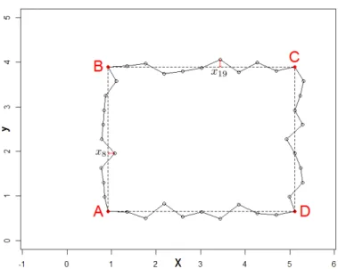
Example 4 A rectangle ABCD with x ∈ R40 whose parameters x1and x2are the location of A, x3
and x4 are the width and the height of ABCD, and x5:13, x14:22, x23:31 and x32:40 are small evenly
distributed perturbations, on the AB, BC, CD and DA segments, respectively.
x1, . . . , x4 are of a magnitude larger than the other parameters to ensure a close-to-rectangular
Figure 21: Example4: a rectangle with varying position, size, and deformation of its sides.
j Eigenvalue Cumulative percentage
1 867.65 48.73 2 866.90 97.42 3 21.46 98.62 4 21.43 99.83 5 0.13 99.83 6 0.13 99.84 7 0.13 99.85 8 0.13 99.86 9 0.12 99.86 10 0.12 99.87 .. . ... ... 39 0.04 99.99 40 0.04 100 41 0 100
Table 6: First PCA eigenvalues for φ(·) = discretization, rectangles with d = 40 parameters (Ex-ample4).
In this example where 4 parameters (position and sizes) mainly explain the differences among shapes, we see that a reconstruction quality of 99.83% is attained with the 4 first eigenvectors vj.
Figure 22 details the eigenvectors. v1 and v2, the most influencing eigenshapes plotted in
black and blue act as translations, while v3and v4 (in red and green) correspond to widening and
heightening of the rectangle. The fluctuations along the segments appear from the 5th eigenshape on. Any shape is retrieved with the d = 40 first eigenshapes which corresponds to the total number of parameters.
Figure 22: 6 first eigenshapes (in the order black, blue, red, green, yellow, purple) of the rectangles in Example4.
Example 5 A straight line joining two fixed points A and B, modified by smooth perturbations r ∈ R29, evenly distributed along [AB] to approximate a smooth curve.
The fifth example is inspired by the catenoid problem [10]. The perturbations r are generated by a Gaussian Process with squared exponential kernel and with length-scale 6 times smaller than [AB]. Therefore, in this example, the N = 5000 r(i)’s used for building ΦΦΦ are not uniformly distributed
Figure 23: Example 5: a straight line joining two points, modified by the perturbations rj to
approximate a curve. Gray: the line joining A and B. Blue, red, yellow and green curve: examples of lines with regular rj perturbations. Red envelope: boundaries for the rj’s.
j Eigenvalue Cumulative percentage
1 2.156 50.258 2 1.251 79.422 3 0.590 93.181 4 0.206 97.973 5 0.065 99.480 6 0.017 99.882 7 0.004 99.975 8 0.001 99.995 9 ε 99.999 10 ε 100 .. . ... ... 28 ε 100 29 ε 100 30 0 100
Table 7: First PCA eigenvalues for φ(·) = discretization, curve with d = 29 parameters. ε means the quantity is not exactly 0, but smaller than 10−3, hence less than 0.04% of the first PCA eigenvalue.
Again, the initial dimension (d = 29) is recovered by looking at the strictly positive eigenvalues. Furthermore, the manifold is found to mainly lie in a lower dimensional space: AN can approximated
in δ = 7 dimensions sincePδ
j=1λj/
PD
j=1λj= 99.975%.
Figure 24 shows the corresponding eigenshapes. The eigenshapes are similar to the ordered modes of the harmonic series with the associated eigenvalues ordered as the inverse of the frequen-cies.
x
y
−0.07
−0.03
0.03
0.07
0.0
1.5
3.5
5.0
1 2 3 4 5 6 7Figure 24: 7 first eigenshapes for the curves of Example5.
Example 6 A NACA airfoil parameterized by three parameters: x = (M, P, T )>∈ R3 where M is
the maximum camber, P is the position of this maximum, and T is the maximal thickness. Figure 25describes the airfoil.
Figure 25: Description of a NACA airfoil with its M , P , T parameters.
In this example, a typical noise-truncation criterion such as discussed in Example5would retain 3 or 4 axes. In Example6 too, the effective dimension can almost be retrieved from the λ’s.
Figure26shows the 4 first eigenshapes (left) as well as the AN manifold (right). The eigenvectors
can be interpreted as a reformulation of the CAD parameters. The first eigenshape (blue) is a symmetric airfoil. Multiplying it by a coefficient (after adding it to the black mean shape) will increase or decrease the thickness of the airfoil, hence it plays a similar role to the T parameter.
j Eigenvalue Cumulative percentage 1 0.2819 54.619 2 0.2203 97.318 3 0.0129 99.814 4 0.0008 99.959 5 0.0001 99.983 6 ε 99.991 7 ε 99.996 8 ε 99.997 9 ε 99.999 10 ε 99.999
Table 8: First PCA eigenvalues of the NACA airfoil with d = 3 parameters (φ(·) is the contour discretization). ε means the quantity is smaller than 10−4, hence less than 0.04% of the first PCA eigenvalue.
The second eigenshape is a cambered airfoil, whose role is similar to M (maximum camber). Last, the third airfoil, which has a much smaller eigenvalue λ3, is very thin, positive in the first part of
the airfoil, and negative in its second part. It balances the camber of the airfoil towards the leading edge or towards the rear and plays a role similar to P , the position of the maximum camber. v3’s effect is complemented by v4.
The analysis of AN (Figure26) is physically meaningful: even though x(i)are sampled uniformly
in X, AN resembles a pyramid in the (v1, v2, v3) basis. Designs with minimal α2 share the same
α3value. Since negative α2’s correspond to wings with little camber, the position of this maximum
camber has very little impact, hence the almost null α3value. By looking at AN, it is learned that
the parameter P does not matter when M is small, which is intuitive but is not expressed by the (M, P, T ) coordinates. Distances in AN are therefore more representative of shape differences. An
additional advantage of analyzing shapes is that correlations in the space of parameters (such as the one between M and P in this example) are discovered and removed, since V is an orthonormal basis. Here, orthogonality between eigenshapes is measured by the standard scalar product in RD.
Depending on the application, there may exist natural definitions of the orthogonality between discretized shapes, which could be used by the PCA.
Example 7 A modified NACA airfoil which is parameterized by d = 22 parameters:
x = (M, P, T, L1, . . . , L19)> ∈ R22 where M , P , T are the standard NACA parameters (Example
6), and where the Li’s correspond to small bumps along the airfoil. Figure 27 describes a NACA
Figure 26: NACA airfoil with d = 3 parameters. Left: mean shape and 4 first eigenshapes (black, blue, red, green, yellow). Right: three first eigencomponents (α1, α2, α3) of the AN manifold.
Figure 27: Description of a NACA airfoil in 22 dimensions. It is a standard NACA airfoil whose intrados and extrados have been modified by bumps of size Li.
j Eigenvalue Cumulative percentage 1 0.2826 53.932 2 0.2205 96.021 3 0.0134 98.580 4 0.0011 98.798 5 0.0006 98.903 6 0.0005 99.006 7 0.0005 99.106 8 0.0005 99.202 9 0.0005 99.293 10 0.0004 99.377 .. . ... ... 19 0.003 99.958 20 0.002 99.992 21 ε 99.995 22 ε 99.998 23 ε 99.999
Table 9: First PCA eigenvalues for φ(·) = discretization, NACA with d = 22 parameters. ε means the quantity is not exactly 0, but smaller than 10−4, hence less than 0.04% of the first PCA eigenvalue.
Here, as in the Example6, the noise-truncation criteria will retain between 6 and 20 dimensions, depending on the reconstruction quality required. Indeed, when looking at specimen of NACA 22 airfoils as the one in the upper left part of Figure28, less than 22 dimensions are expected to be necessary to retrieve an approximation of sufficient quality.
The analysis of eigenshapes, shown in Figure 29, is similar to the one of Example 6. Small details that act on the airfoil such as the bumps only appear from the 4th eigenshape on. Not taking them into account leads to a weaker reconstruction, as shown in the bottom part of Figure 28.
Figure 28: Left: examples of NACA 22 airfoils. Even though the true dimension is 22, less di-mensions may suffice to approximate the shapes well enough. Right: reconstruction scheme of any NACA 22 shape: a weighted deviation from the mean shape φφφ in the direction of the eigenshapes. Bottom: example of shape reconstruction (red) using 2, 3, 6 or 20 eigenshapes. The more vj’s, the
Mean discretization 1st eigenvector 2nd eigenvector 3rd eigenvector 4th eigenvector 5th eigenvector 6th eigenvector
Figure 29: Mean shape (black) and 6 first eigenshapes (blue, red, green, yellow, purple, pink) for the NACA with 22 parameters. The three first eigenvectors are similar to those observed on Figure 26for the original NACA 3. Fluctuations along the eigenshapes are found from the 4th eigenshape on. They allow to reconstruct the local refinements (bumps) of the airfoils.
According to these experiments, the eigenvectors vj, j ∈ {d+1, . . . , D}, can already be discarded
without even considering the values of the associated objective functions since the d first shape modes explain the whole variability of the discretized shapes. In practice, to filter numerical noise and to remove non-informative modes in shapes that are truly over-parameterized, we only consider the d0first eigenshapes, d0:= min(d, ˜d) where ˜d corresponds to the smallest number of axes that explain more than a given level of diversity in Φ (e.g. 99.9, 99.95 or 99.99%), measured by 100 ×Pd˜
j=1λj/P D
j=1λj. Another alternative is to define ˜d according to the dimensions for which
λj/λ1 is smaller than a prescribed threshold (e.g. 1/1000). Even though the notation D is kept,
the eigenvectors vj and the principal components α
j, are considered to be null ∀j > d0 so that in
fact D = d0 in the following.
3
GP models for reduced eigenspaces
Building a surrogate model in the space of principal components has already been investigated in the context of reduced order models [5]. In most applications, the dimension reduction is carried out in the output space, which has large dimension when it corresponds to values on a finite element mesh. The response is approximated by a linear combination of a small number of modes, and the metamodel is a function of the modes coefficients. The construction of surrogates with inherent dimensionality reduction has also been considered. In the active subspace method [11], the dimension reduction comes from a linear combination of the inputs which is carried out by projecting x onto the hyperplane spanned by the directions of largest ∇f (x) variation. The reduced-dimension GP is then Y (W>x) with W ∈ Rd×δ containing these directions in columns. In [34], cross-validation is employed for choosing the number of such axes. An application to airfoils is given in [26] where the authors take the directions of largest drag and lift gradients as columns of W, even though this basis is no longer orthogonal. Another related technique with a Y (W>x) GP which does not require the knowledge of ∇f (x) is the Kriging and Partial Least Squares (KPLS) method [8], where x is projected onto the hyperplane spanned by the first δ axes of a PLS regression [19]. The dimension reduction is output-driven but W is no longer orthogonal, and information may be lost when n < d0because any shape (of effective dimension d0) cannot be exactly reconstructed (Equation 3) with these n vectors. Coordinates in the PLS space are therefore incomplete and metamodeling loses precision when n is too small. In the same spirit, a double maximum-likelihood procedure is developed in [47] to build an output-related and orthogonal matrix W for the construction of a Gaussian Process with built-in dimensionality reduction. Rotating the design space through hyperparameters determined by maximum likelihood is also performed in [33]. Table10summarizes the existing literature for building such GPs as well as the approach introduced in Section 3.2.2 (last column).
3.1
Unsupervised dimension reduction
Instead of the space of CAD parameters x, we reduce the dimension of the input space by building the surrogate with information from the space of shape representations, Φ, as in [25]. To circumvent the high dimensionality of Φ ⊂ RD, a linear dimension reduction of φ(x) is achieved by building the
model in the space spanned by W>φ(x). A natural candidate for W is a restriction to few columns (eigenshapes) of the matrix V. Notice that contrarily to the other dimension reduction techniques which operate a linear dimension reduction of x, this approach is nonlinear in x since it operates
Model Y (W>x) Y (W>φ(x)) Ya(W>
aφ(x)) + Ya(W>aφ(x))
Dimension reduction Linear in x Nonlinear in x Nonlinear in x; group-additive model Construction of W Active subspaces [11,34,26] PLS [8] GP hyperparameters [47,33] Sensitivity analysis [4] PLS [25]
Selection of mapped variables through penalized likelihood
(Section3.2.1)
Table 10: An overview of GP models with built-in dimensionality reduction.
linearly on the nonlinear transformation φ(x). Also, it operates on a better suited representation of the designs, their shapes, instead of their parameters.
A first idea to reduce the dimension of the problem is to conserve the δ first eigenvectors vj
according to some reconstruction quality criterion measured by the eigenvalues. Given a threshold T (e.g., 0.95 or 0.99), only the first δ modes such that
Pδ j=1λj
PD
j=1λj > T are retained in V1:δ ∈ R
D×δ
because they contribute for 100 × T % of the variance in Φ. The surrogate model is implemented in the space of the δ first principal components as
Y (ααα1:δ) = Y (V>1:δ(φ(x) − φφφ)). (5)
Using a stationary kernel for the Y (ααα1:δ) GP, i.e. k(ααα1:δ, ααα01:δ) = ˜k(kααα1:δ− ααα01:δkRδ), the
corre-lation between designs is k(ααα1:δ, ααα01:δ) = ˜k(kV>1:δ(φ(x) − φ(x0))kRδ) = ˜k(r) with r
2 = (φ(x) −
φ(x0))>M(φ(x) − φ(x0)) where M = V1:δV>1:δ is a D × D matrix with low rank (δ). Hence, this
model implements a Gaussian Process in the Φ space with an integrated linear dimensionality reduction step [37]. Note that the kernel is non-stationary in the original X space.
The approaches [11,8,47] mainly differ from that proposed in Equation (5) in the construction of the reduced basis: in Equation (5), dimension reduction is carried out without the need to call the expensive f (x) (or its gradient): the directions of largest variation of an easy to compute mapping φ(·) are used instead. This also prevents from a spurious or incomplete projection when n is smaller than D and avoids recomputing the basis at each iteration.
This is nonetheless a limitation since the Y (ααα1:δ) approach relies only on considerations about
the shape geometry. The output y is not taken into account for the dimension reduction even though some vj, j ∈ {1, . . . , δ} may influence y or not. Two shapes which differ in the α
j components
with j ≤ δ may behave similarly in terms of output y, so that further dimension reduction is possible. Vice versa, eigencomponents that have a small geometrical effect and were neglected may be reintroduced because they matter for y.
As an illustration consider the red and black shapes of Figure 30. Both are associated to parameters x and x0 and their discretizations φ(x) and φ(x0) are quite different. Depending on the
objective function, f (x) and f (x0) might differ widely. However, when considering the φφφ+Pδ
j=1αjvj
reconstruction with δ = 3, they look very similar because ααα1:3 ≈ ααα01:3. Even though V1:3 :=
{v1, v2, v3} is a tempting basis because it explains 98.5% of the discretizations variance, it is not
a good choice if f (x) and f (x0) are different: because of continuity assumptions a surrogate model would typically suffer from inputs ααα ≈ ααα0 with y 6= y0.
For this reason, instead of building the surrogate in the space spanned by the most relevant shape ⊂ V basis of the most output-influencing eigenshapes
Figure 30: Example of two different shapes (black and red) whose reconstruction in the space of the three first eigenshapes is very similar.
α
ααa. Additionally, since the remaining “inactive” components αααa refine the shape and might explain
small fluctuations of y, instead of omitting them (which is equivalent to stating αααa = 0), we would
like to keep them in the surrogate model while prioritizing αααa: a GP Ya(Waφ(x)) + Ya(Waφ(x))
is detailed in Sec. 3.2.2.
3.2
Supervised dimension reduction
3.2.1 Selection of active eigenshapes
To select the eigencomponents that impact y the most, the penalized log-likelihood [53] of a regular, anisotropic GP in the high dimensional space of ααα’s is considered,
max
ϑ plλ(α
αα(1:n), y1:n; ϑ) where plλ(ααα(1:n), y1:n; ϑ) := l(ααα(1:n), y1:n; ϑ) − λkθθθ−1k1 (6)
The ϑ are the GP’s hyper-parameters made of the length-scales θj, a constant mean term β, and
the variance of the GP σ2. ααα(1:n) are the eigencomponents of the evaluated designs x(1), . . . , x(n),
and y1:nthe associated outputs, y1:n= (y1, . . . , yn)>= (f (x(1)), . . . , f (x(n)))>. The mean and the
variance terms can be solved for analytically by setting the derivative of the penalized log-likelihood (6) equal to 0 which yields
b β := 1 >R−1 θ θ θ y1:n 1>R−1 θ θ θ 1 and bσ2:= 1 n(y1:n− 1 bβ) >R−1 θ θ θ (y1:n− 1 bβ) (7)
where Kϑ is the covariance matrix with entries Kϑij = cσ2kθθθ(x(i), x(j)), with determinant |Kϑ| and
Rθθθ is the correlation matrix, Rij = kθθθ(x(i), x(j)). The (concentrated) penalized log-likelihood of
this GP is plλ(ααα(1:n), y1:n; ϑ) = − n 2log(2π) − 1 2log(|Kϑ|) − 1 2(y1:n− 1 bβ) >K−1 ϑ (y1:n− 1 bβ) − λkθθθ−1k1 (8)
The penalization is applied to θθθ−1 := (1/θ1, . . . , 1/θD)>, the vector containing the inverse
length-scales of the GP. It is indeed clear [4] that if θj → +∞, the direction vj has no influence
on y as all the points are perfectly correlated together, making the GP flat in this dimension. The L1penalty term applied to the θ
j’s performs variable selection: this Lasso-like procedure promotes
zeros in the vector of inverse length-scales, hence sets many θj’s to +∞. Few directions with small
θjare selected and make the active dimensions, αααa (step 3 in Figure1). Even if the maximization
are analytically known [38], and because the L1penalty convexifies the problem. We solve it using
standard gradient-based techniques such as BFGS [27] with multistart.
Numerical experiments not reported here for reasons of brevity have shown that most local optima to this problem solely differ in θj’s that are already too large to be relevant and consistently
yield the same set of active variables αααa. Notice that in [53], a similar approach is undertaken
but the penalization was applied on the reciprocal variables w = (w1, . . . , wD)> with wj = 1/θj.
In our work, the inverse length-scales are penalized, the gradient of the penalty is proportional to 1/θ2j. This might help the optimizer since directions with θj’s that are not large yet are given more
emphasis. In comparison, the w penalty function’s gradient is isotropic. Since we can restrict the number of variables to d0 D with no loss of information (cf. discussion at the end of Section2.3), the dimension of Problem (6) is substantially reduced which leads to a more efficient resolution. Because the αj’s have zero mean and variance λj, they have magnitudes that decrease with j.
When m < n, 1/θn is typically larger than 1/θm, meaning that the optimizer is better rewarded
by diminishing 1/θn than 1/θm. Starting from reasonable θj values2 the first θj’s are therefore
less likely to be increased in comparison with the last ones, i.e. they are less likely to be found inactive. This can be seen as a bias which can be removed by scaling all αj’s to the same interval.
However, we do not normalize the ααα variables for two reasons. First, since the αj’s correspond to
reconstruction coefficients associated to normalized eigenshapes (kvjk
RD = 1), they share the same
physical dimension and can be interpreted in the same manner. Second, this bias is equivalent to assuming that the most significant shape variations are responsible for the largest output variations, which is a reasonable prior. In experiments that are not reported here for the sake of brevity, we have noticed that a BFGS algorithm optimizing Problem (6) got trapped by weak local optima more frequently when the αj’s were normalized.
Definition 1 (Selection of active dimensions) Let a GP be indexed by α1, . . . , αD∈ [αααmin, αααmax] ⊂
RD and {ααα(1:n), y(1:n))} be the data to model. The length-scales θθθ of the GP are set by maximizing
the L1 penalized concentrated log-likelihood of Equation (8). A dimension j is declared active if
θj range(αj) ≤ 10 × min i=1,...,D θi range(αi) .
The δ such active dimensions are denoted αααa = (αa1, . . . , αaδ) ∈ R
δ.
Since the αj’s have different (decreasing) ranges, the length-scales have to be normalized by the
range of ααα(1:n)j to be meaningful during this θj comparison. Our implementation extends the
likeli-hood maximization of the kergp package [14] to include the penalization term. After a dimensional analysis of plλ, we have chosen to take λ = Dn to balance both terms. Other techniques such as
cross-validation or the use of different λ’s for obtaining a pre-defined number of active components can also be considered.
On the NACA 22 benchmark with few observations of f (·) (n = 15 here), Figure 31gives the only few active components that are selected by the penalized maximum likelihood procedure. The three first principal axes, v1, v2 and v3 are retained when considering the drag (top). Indeed,
these are the eigenshapes that globally impact the shape the most and change its drag. When the output y is the lift (bottom), only the second principal axis is selected. This eigenshape modifies the camber of the shape, which is known to highly impact the lift. The other eigenvectors are
detected to be less critical for y’s variations. When n grows, more eigenshapes get selected because they also slightly impact the output. For instance when n = 50, some eigenshapes that contain bumps (the 4th, the 5th, the 8th, etc.) are selected for modeling the lift. They also contribute to changing the camber of the airfoil, hence its lift.
Figure 31: Variable selection on the NACA 22 benchmark by penalized maximum likelihood. For the drag (top), the three first eigenshapes that act on the shape, hence on its drag, are selected (red coefficients). For the lift, only the second eigencomponent (v2) is selected (bottom). Indeed
v2 modifies the camber of the airfoil, hence it plays a major role on the lift. The other eigenbasis
vectors (green coefficients) are estimated to be less influential on y.
3.2.2 Additive GP between active and inactive eigenshapes Completely omitting the non-active dimensions, αααa
∈ RD−δ, and building the surrogate model Y (·)
in the sole αααa space may amount to erasing some geometric patterns of the shapes which contribute
to small variations of y. For this reason, an additive GP [16,17] with zonal anisotropy [1] between the active and inactive eigenshapes is considered (step 4 in Figure1):
Y (ααα) = β + Ya(αααa) + Ya(αααa). (9) Ya(αααa) is the anisotropic main-effect GP which works in the reduced space of active variables.
It requires the estimation of δ + 1 hyper-parameters (the length-scales θj and a GP variance σa2)
and aims at capturing most of y’s variation, related to αααa’s effect. Ya(αααa) is a GP over the large
space of inactive components. It is a GP which just takes residual effects into account. To keep Ya(αααa) tractable, it is considered isotropic, i.e., it only has 2 hyper-parameters, a unique
length-scale θa and a variance σ2a. In the end, even though Y (ααα) operates with ααα’s ∈ RD and there are
fewer observations than dimensions3, n D, it remains tractable since only a total of δ + 3 n
hyperparameters have to be learned, which guarantees the identifiability, i.e. the unicity of the hyperparameters solution even when the number of observations is small. Although the αj’s have
different ranges, they are homogeneous in that they all multiply normalized eigenshapes. Thus, the distances inside the shape manifold, A, should be relevant and an isotropic model is a possible assumption, which again, tends to emphasize eigenshapes that appear the most within the designs. This additive model can be interpreted as a GP in the αααa space, with an inhomogeneous noise fitted by the Ya(·) GP [15]. It aims at modeling a function that varies primarily along the active dimensions, and fluctuates only marginally along the inactive ones, as illustrated in Figure32.
Figure 32: Example of a function that primarily varies along the αααa direction, and secondarily
along αααa. If αααa is omitted, one implicitly considers the restriction of f (·) to the gray plane where
α ααa = 0.
Denoting ka and ka the kernels of the GPs, the hyper-parameters ϑa = (θa1, . . . , θaδ, σ
2 a) and
ϑa= (θa, σ2a) are estimated by maximizing the log-likelihood of (9) given the observed data y1:n,
lY(ααα(1:n), y1:n; ϑa, ϑa) = − n 2 log 2π − 1 2log(|K|) − 1 2(y1:n− 1 bβ) >K−1(y 1:n− 1 bβ),
using the kergp package [14]. K = Ka + Ka, with Kaij = σ2aka(αααa(i), αααa(j)), and Kaij =
σ2
aka(αααa(i), αααa(j)), and bβ is given by Equation (7). The correlation between ααα and ααα0 being
k(ααα, ααα0) = σ2aka(αααa, αααa0) + σa2ka(αααa, αααa0), the kriging predictor and variance of this additive GP
are [37]
m(ααα) = 1nβ + k(αb αα, ααα(1:n))>K−1(y1:n− 1nβ)b s2(ααα) = σ2a+ σ2a− k(ααα, ααα(1:n))>K−1k(ααα, ααα(1:n))
(10)
3.3
Experiments: Metamodeling in the eigenshape basis
We now study the performance of the variable selection and of the additive GP described in the previous section. The different versions of GPs that are compared are the following:
• GP(X) is the GP in the original space of parameters X;
• GP(ααα ) indicates the GP is built in the space of (to be specified) principal components; • GP(αααa
) means the GP works with the active ααα’s only; • AddGP(αααa+ αααa
) refers to the additive GP (Section3.2.2).
We equip the example designs2,4,5and7(Section2.3) with objective functions f (x) that are to be modeled by the fitted GPs. For each function, the predictive capability of different models is compared on a distinct test set using the R2 coefficient of determination. Later, in Section4.3.2, the objective functions will be optimized.
• Example 2: f2(x) = r − πr2− k(x, y)> − (3, 2)>k2, where x, y and r correspond to the
position of the center and the radius of the over-parameterized circle (and accessible through x), respectively.
• Example 4: f4(x) = kΩt− Ωx˜k22 where ˜x := x − (x1+ 2.5, x2+ 2.5, 0, . . . , 0)> corresponds
to the centered design, and Ωt, Ω˜x are the nodal coordinates of the shapes, see Figure21.
The goal is to retrieve a target shape t = (t1, . . . , t40)> whose lower left point (A) is set at
t1 = t2 = 2.5 with the flexible rectangle defined by x. The A point of any shape x is first
moved towards (2.5, 2.5) too, and f4 measures the discrepancy. Here, the target t is the
rectangular heart shown in Figure33.
Figure 33: Rectangular heart target shape of Example4. • Example5: f5(r) = 2π
RyB
yA r(y)p1 + r
0(y)2dy: inspired by the catenoid problem [10], we aim
at finding a regular curve joining two points A = (0, yA) and B = (1, yB), with the smallest
axisymmetric surface. The curve r(y) is the straight line between A and B, modified by r = (r1, . . . , r29)>, see Figure23.
• Example7: the objective functions are the lift coefficient and the drag coefficient of the airfoil, f7L, f7D. The latter are computed using a commercial Computational Fluid Dynamics (CFD)
computer code.
Over-parameterized circle (Example 2)
For the over-parameterized circle, the objective function is f2(x) = r − πr2− k(x, y)>− (3, 2)>k2,
where x, y and r correspond to the position of the center and the radius of the circle (accessible through x), respectively. f2explicitly depends on the parameters that truly define the circle. Three
models are compared
• A model using the CAD parameters x ∈ R39;
• A model using the 3 first eigencomponents, (α1, α2, α3);
• A model built over the true circle parameters (x, y, r).
Table 11 gives the average R2 over 10 runs with different space-filling DoEs of size n = 20, 50, 100, 200. Since d = 39 > 20, no GP was fitted in the CAD parameter space when n = 20.
f2 is easily learned by the surrogate model as shown by large R2 values. Obviously, the quality
n GP(X) GP(ααα1:3) GP(True)
20 - 0.99741 0.99701
50 0.78193 0.99954 0.99951 100 0.86254 0.99984 0.99985 200 0.93383 0.99992 0.99997
Table 11: Average R2 over 10 runs for the prediction of f2. GP(X) is the GP in the 39-dimensional
CAD parameter space, GP(ααα1:3) corresponds to a GP fitted to the 3 first principal components
α1, α2, α3, and GP(True) to the GP with the space of minimal circle coordinates.
outperforms the GP in the CAD parameters space (GP(X), d = 39). Yet, the GP(ααα1:3) performs
as well (and even better for small n’s) as GP(True). Heart target (Example 4)
We turn to the metamodeling of f4. It is a 40-dimensional function, f4(x) = kΩt − Ωx˜k22 that
explicitly depends on the CAD parameters. Unlike the previous test problem, the shapes do not have superfluous parameters since all xj’s are necessary to retrieve t.
7 different models detailed through Sections3.1and3.2are investigated. GP(X), the standard GP carried out in the space of CAD parameters. GP(ααα1:40), the metamodel built in the space of
40 first principal components. Indeed, Table 6 informed us that any shape is retrieved via its 40 first eigenshape coefficients. To build surrogates in reduced dimension, considering the cumulative eigenvalue sum in Table6, GP(ααα1:2), GP(ααα1:4) and GP(ααα1:16) are models that consider the 2, 4 and
16 first principal components only. Finally, GP(αααa) and AddGP(αααa+ αααa) are also compared.
Table 12reports the average R2 indicator over 10 runs starting with space-filling DoEs of size n = 20, 50, 100, 200. Figure34shows a boxplot of the results (for the sake of clarity, only runs with R2 ≥ 0.8 are shown). The input dimension for GP(X) and for GP(ααα1:40) is too large for coping
with n = 20 observations. GP(ααα1:40) is given beside GP(X) because both GPs have the same input
space dimension. n GP(X) GP(ααα1:40) GP(ααα1:2) GP(ααα1:4) GP(ααα1:16) GP(αααa) AddGP(αααa+ αααa) 20 - - -0.063 0.979 0.844 0.935 0.967 50 0.455 0.542 -0.009 0.984 0.968 0.983 0.991 100 0.662 0.868 0 0.986 0.986 0.986 0.997 200 0.873 0.988 0 0.987 0.991 0.987 0.999
Table 12: Average R2 over 10 runs when metamodeling f4.
The benefits of the additive GP appear to be threefold. First, it ensures sparsity by selecting a small number of eigenshapes for the anisotropic part of the kernel. A high-dimensional input space hinders the predictive capabilities when n is small, as confirmed by the weak performance of GP(X), GP(ααα1:40) and even GP(ααα1:16) for n = 20. When n increases, higher-dimensional models become
more accurate. For n = 100 and n = 200, the model with 16 principal components outperforms the one with 4 principal components, even though the latter was more precise with n = 20 or n = 50 observations. In the case n = 200, even GP(ααα1:40) outperforms the 4 dimensional one (GP(ααα1:4)).
Figure 34: Boxplots of R2 coefficient for the different models, rectangle test case (Example4).
“input space errors”. When few observations are available, these models suffer from the curse of dimensionality, but become accurate as soon as their design space gets infilled enough. With more observations, GP(ααα1:40) may become the best model.
Besides the dimension reduction, the selection of eigenshapes that truly influence the output is also critical. According to Table 6, a tempting decision to reduce the dimension would be to retain the two first principal components, i.e. GP(ααα1:2). But since the 2 first eigenshapes act on the
shape’s position (see Figure22) to which f4 is insensitive, this is a weak option, as pointed out by
the R2 scores which are close to 0 for this model. Here, the selected variables are usually the 3rd and the 4th eigenshape which act on the size of the rectangle, hence are of first order importance for f4. In about 30% of the runs, they are accompanied by the first and the second one, and more
rarely by other eigenshapes.
Third, the AddGP(αααa+ αααa) outperforms GP(αααa). Indeed, the less important eigenshapes (from
a geometric point of view) v5, . . . , v40 locally modify the rectangle, and allow the final small
im-provements in f4. This highlights the benefits of taking the remaining eigenshapes which act as
local shape refinements into account.
Last, even though their input spaces have the same dimension, GP(ααα1:40) consistently
outper-forms GP(X). This confirms our comments about the NACA manifold of Figure26: the eigenshapes are a better representation than the CAD parameters for statistical prediction.
Catenoid shape (Example5)
In relation with the catenoid, we introduce the objective function f5(r) = 2π
RyB
yA r(y)p1 + r
0(y)2dy.
f5 is an integral related to the surface of the axisymmetric surface given by the rotation of a curve
deviations r = (r1, . . . , r29)>. Only r’s generated by a GP that lead to a curve inside a prescribed
envelope (see Figure23) are kept in the same spirit as [26] where a smoothing operator is applied to consider realistic airfoils. With this, it is expected that less than 29 dimensions suffice to accurately describe all designs. This is confirmed by the eigenvalues in Table 7 and the true dimensionality detected to be 7.
In this experiment, we compare the predictive capabilities of six models. The first one is the classical GP(X). The objective function explicitly depends on r but its high-dimensionality may be a drawback for metamodeling. Even though less dimensions are necessary and many eigenshapes correspond to noise, a GP fitted to all d = 29 eigenshapes, GP(ααα1:29), is considered. Along with
it, GP(ααα1:4) and GP(ααα1:7) are considered. The former is an unsupervised dimension reduction,
considering the λj’s, while the latter is the full dimensional eigenshape GP, since the eigenshapes
8 to 29 are non-informative. Finally, the GPs with variable selection GP(αααa
) and AddGP(αααa+ αααa
), are also compared.
Table 13reports the average R2 indicator over 10 runs starting with space-filling DoEs of size n = 20, 50, 100, 200. Figure35shows a boxplot of the results (for the sake of clarity, only runs with R2 ≥ 0.95 are shown). The input dimension for GP(X) and for GP(ααα1:29) is too large for coping
with n = 20 observations. GP(ααα1:29) is given beside GP(X) because these GPs have the same input
space dimension. n GP(X) GP(ααα1:29) GP(ααα1:4) GP(ααα1:7) GP(αααa) AddGP(αααa+ αααa) 20 - - 0.966 0.958 0.914 0.992 50 0.976 0.925 0.954 0.987 0.938 0.997 100 0.992 0.968 0.958 0.997 0.957 0.999 200 0.997 0.981 0.952 0.998 0.951 0.999
Table 13: Average R2 over 10 runs for the metamodeling of f5.
These results indicate a better performance of AddGP(αααa+ αααa) which benefits from the
priori-tization of the most influential eigenshapes in the additive model and, at the same time, accounts for all the 7 eigenshapes. Modeling in the space of the full ααα’s (GP(ααα1:7)) performs fairly well too
because the low true dimensionality (7). Despite its lower dimensionality, GP(ααα1:4) does not work
well. This is because the refinements induced by v5, v6and v7 are disregarded while acting on f 5.
This explanation also stands for the moderate performance of GP(αααa) in which mainly the 4 first principal components are selected. Including the remaining components in a coarse GP as is done inside AddGP(αααa+ αααa) increases the performance.
Even though there are d = 29 CAD parameters, GP(X) exhibits correct performances: since only smooth curves are considered, they are favorable to GP modeling and the curse of dimensionality is damped. In this example, considering all 29 eigenshapes (GP(ααα1:29)), even though it was assumed
that solely 7 were necessary, leads to the worst results, since the non-informative eigenshapes augment the dimension without bringing additional information.
NACA 22 airfoil (Example 7)
The last example brings us closer to real world engineering problems. The objective functions associated to the NACA airfoil with 22 parameters (Example7), f7L and f7D are the lift and the