Publisher’s version / Version de l'éditeur:
Journal of Structural Engineering, 129, Feb 2, pp. 253-259, 2003-02-01
READ THESE TERMS AND CONDITIONS CAREFULLY BEFORE USING THIS WEBSITE. https://nrc-publications.canada.ca/eng/copyright
Vous avez des questions? Nous pouvons vous aider. Pour communiquer directement avec un auteur, consultez la
première page de la revue dans laquelle son article a été publié afin de trouver ses coordonnées. Si vous n’arrivez pas à les repérer, communiquez avec nous à PublicationsArchive-ArchivesPublications@nrc-cnrc.gc.ca.
Questions? Contact the NRC Publications Archive team at
PublicationsArchive-ArchivesPublications@nrc-cnrc.gc.ca. If you wish to email the authors directly, please see the first page of the publication for their contact information.
NRC Publications Archive
Archives des publications du CNRC
This publication could be one of several versions: author’s original, accepted manuscript or the publisher’s version. / La version de cette publication peut être l’une des suivantes : la version prépublication de l’auteur, la version acceptée du manuscrit ou la version de l’éditeur.
For the publisher’s version, please access the DOI link below./ Pour consulter la version de l’éditeur, utilisez le lien DOI ci-dessous.
https://doi.org/10.1061/(ASCE)0733-9445(2003)129:2(253)
Access and use of this website and the material on it are subject to the Terms and Conditions set forth at Effect of strength and fiber reinforcement on fire resistance of high-strength concrete columns
Cheng, F. P.; Wang, T. C.; Sultan, M. A.
https://publications-cnrc.canada.ca/fra/droits
L’accès à ce site Web et l’utilisation de son contenu sont assujettis aux conditions présentées dans le site LISEZ CES CONDITIONS ATTENTIVEMENT AVANT D’UTILISER CE SITE WEB.
NRC Publications Record / Notice d'Archives des publications de CNRC:
https://nrc-publications.canada.ca/eng/view/object/?id=e75a0c1e-e724-4d2f-aad3-fae28adc8702 https://publications-cnrc.canada.ca/fra/voir/objet/?id=e75a0c1e-e724-4d2f-aad3-fae28adc8702
Effect of strength and fiber reinforcement on fire resistance of high-strength concrete columns
Kodur, V.K.R.; Cheng, F-P.; Wang, T-C.; Sultan, M.A.
NRCC-45005
A version of this document is published in / Une version de ce document se trouve dans : Journal of Structural Engineering, v. 129, no. 2, Feb. 2003, pp. 253-259
Effect of Strength and Fiber Reinforcement on the Fire Resistance of High Strength Concrete Columns
by
V.K.R. Kodur1, Fu-Ping Cheng2, Tien-Chih Wang3 and M.A. Sultan1
ABSTRACT
In this paper, results from fire resistance experiments on five types of reinforced concrete columns are presented. The variables considered in the study include concrete strength (NSC and HSC), aggregate type (siliceous and carbonate aggregate), and fiber reinforcement (steel and polypropylene fibers). Data from the study is used to determine the structural behaviour of HSC columns at elevated temperatures. A comparison is made of the fire resistance performance of HSC columns with that of normal strength concrete (NSC) and fiber-reinforced HSC columns. The factors that influence the thermal and structural behaviour of HSC concrete columns under fire conditions are discussed. The results show that the fire resistance of a NSC column is higher than that of a HSC column. Also, the addition of polypropylene fibers and the use of carbonate aggregate improve fire resistance.
Keywords: fire resistance, high strength concrete, high temperature behaviour, reinforced
concrete columns, spalling
INTRODUCTION
In recent years, the construction industry has shown significant interest in the use of high strength concrete (HSC). This is due to the improvements in structural performance, such as high strength and durability, that it can provide compared to traditional, normal strength concrete (NSC). Recently, the use of high strength concrete, which was previously in applications such as bridges, off-shore structures and infrastructure projects, has been extended to high rise buildings. One of the major uses of HSC in buildings is for columns. The columns form the main load bearing components in a building and hence, the provision of appropriate fire safety measures is one of the major safety requirements in building design (NBC 1995).
In recent years, the design standards for concrete structures have been updated with detailed specifications for the design of HSC structural members under normal conditions. However, in many of the design standards (CSA 1994), there are no guidelines for the fire resistance design of HSC structural members.
The results of fire tests in a number of laboratories (Diederichs et al. 1995, Kodur and McGrath 2001) have shown that there are well-defined differences between the properties of
1
Senior Research Officer, Inst. for Res. in Constr., National Research Council, Ottawa, ON, Canada. E-mail: Venkatesh.kodur@nrc.ca
2 Ph. D. Student, Department of Civil Engineering, National Chiao Tung University, HsinChu, Taiwan. 3 Associate Prof., Department of Civil Engineering, National Chiao Tung University, HsinChu, Taiwan
HSC and NSC at elevated temperatures. Further, concern has developed regarding the occurrence of explosive spalling when HSC is subjected to rapid heating, as in the case of a fire (Diederichs et al. 1995, Phan 1996).
A collaborative research project was initiated between National Research Council of Canada (NRC) and National Chiao Tung University (NCTU), Taiwan, to develop fire resistance design guidelines for the use of high strength concrete and for possible incorporation in codes and standards. One component of this project covered detailed fire resistance experimental studies on five different types of HSC columns. The main objective of this research was to determine the behaviour of HSC at elevated temperatures and to develop solutions to minimize spalling and thus enhance fire resistance. In this paper, the results of experiments are used to trace the structural behaviour of HSC concrete columns at elevated temperatures.
RESEARCH SIGNIFICANCE
In buildings, HSC structural members are to be designed to satisfy the requirements for serviceability and safety limit states. One of the major safety requirements in building design is the provision of appropriate fire safety measures for structural members. The basis for this requirement can be attributed to the fact that, when other active measures for containing the fire fail, structural integrity is the last line of defence.
The fire safety measures for structural members are measured in terms of fire resistance. Fire resistance is defined as the duration during which a structural member exhibits resistance with respect to structural integrity, stability and temperature transmission under fire conditions. The fire resistance of a structural member is dependent on the geometry, the materials used in construction, the load intensity and the characteristics of the fire exposure itself.
Generally, concrete structural members exhibit good performance under fire situations. Studies show, however, that the performance of HSC is different from that of NSC and may not exhibit good performance in fire. Further, the spalling of concrete under fire conditions is one of the major concerns due to the low water-binder ratio in HSC. The spalling of concrete exposed to fire has been observed under laboratory and real fire conditions (Phan 1996, Matsumoto 1994). Spalling, which results in the rapid loss of concrete during a fire, exposes deeper layers of concrete to fire temperatures, thereby increasing the rate of transmission of heat to the inner layers of the member, including to the reinforcement.
Spalling is theorized to be caused by the build-up of pore pressure during heating (Diederichs et al. 1995, Kodur et al. 1998). HSC is believed to be more susceptible to this pressure build-up because of its low permeability compared to NSC. The extremely high water vapour pressure, generated during exposure to fire, cannot escape due to the high density of HSC and this pressure often reaches the saturation vapour pressure. At 300°C, the pressure reaches about 8 MPa. Such internal pressures are often too high to be resisted by the HSC mix having a tensile strength of about 5 MPa (Phan 1996).
Data from various studies (Diederichs et al. 1995, Kodur and McGrath 2001, Phan 1996) show that fire performance of HSC, in general, and spalling, in particular, is affected by the following factors:
• concrete strength
• moisture content of concrete • concrete density
• heating rate
• specimen dimensions and shape • loading conditions
• fiber reinforcement • aggregate type
• reinforcement layout and configuration
To determine the effect of strength and the addition of fiber reinforcement on the behaviour of loaded HSC columns under fire conditions, studies were undertaken on five reinforced concrete columns. In this paper, the comparative performance of HSC and NSC columns is discussed by considering the results from five reinforced concrete columns: four of HSC and one of NSC. The variables considered are strength (NSC and HSC), aggregate type (siliceous and carbonate aggregate), and fiber reinforcement (steel and polypropylene fibers).
EXPERIMENTAL STUDIES Test Specimens
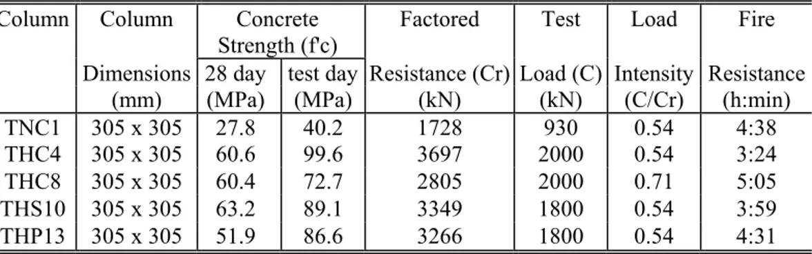
The experimental program consisted of conducting fire resistance tests on five reinforced concrete columns. Four of these columns, THC4, THC8, THS10 and THP13, were of HSC while the fifth one, TNC1, was made with NSC. All columns were 3810 mm long and of square cross section of 305 mm. The dimensions of the column cross section and other specifics of the columns are given in Table 1.
All columns had four, 25 mm, longitudinal bars. The bars were tied with 10 mm ties at a spacing of 75 mm in both ends and 145 mm in the middle. The main reinforcing bars and ties had a specified yield strength of 420 MPa and 280 MPa, respectively. Figure 1 shows the elevation and cross-sectional details of the columns together with the locations of the ties.
Five batches of concrete were used in fabricating the columns. The concrete mix for Batch 1 was of NSC, while the mixes for Batch 2-5 were of HSC. Steel and polypropylene fiber reinforcements were added to Batch 4 and Batch 5, respectively. The coarse aggregate in Batch 3 was of carbonate type, while the other Batches were made with siliceous aggregate. Columns TNC1, THC4, THC8, THS10 and THP13 were fabricated from Batch 1, Batch 2, Batch 3, Batch 4 and Batch 5, respectively. All five batches of concrete were made with general purpose, Type 1 Portland cement. The mix proportions, per cubic metre of concrete, in the five batches are given in Table 2.
The average compressive cylinder strength of the concrete, measured 28 days after pouring and on the day of the testing, are given in Table 1. The moisture condition at the centre of the column was also measured on the day of the test. The moisture conditions of Columns TNC1, THC2, THC8, THS10 and THP13 are approximately equivalent to those in equilibrium with air of 90%, 78%, 93%, 80% and 94% relative humidity, respectively, at room temperature.
Type-K Chromel-alumel thermocouples, 0.91 mm thick, were installed at mid-heights in the columns for measuring concrete and rebar temperatures at different locations in the cross section. The location and numbering of the thermocouples on the cross-section is shown in Figure 2. Test Apparatus
The tests were carried out by exposing the columns to heat in a furnace specially built for testing loaded columns. The furnace consists of a steel framework supported by four steel columns, with the furnace chamber inside the framework. The test furnace was designed to produce conditions, such as temperature, structural loads and heat transfer, to which a member might be exposed during a fire. The furnace has a loading capacity of 1,000 t. Full details on the characteristics and instrumentation of the column furnace are provided by Lie (1908).
Test Conditions and Procedure
The columns were installed in the furnace by bolting the endplates to a loading head at the top and to a hydraulic jack at the bottom. The end conditions of the columns were fixed-fixed for all tests. For each column, the length exposed to fire was approximately 3000 mm. At high temperature, the stiffness of the unheated column ends, which is high in comparison to that of the heated portion of the column, contributes to a reduction in the column effective length. In previous studies (Lie and Woollerton 1988), it was found that, for columns tested fixed at the ends, an effective length of 2000 mm represents experimental behaviour.
All columns were tested under concentric loads. Column TNC1 was subjected to a load of 930 kN, which is equal to 54% of the ultimate load according to CSA A23-3 (1994). Column THC4 was subjected a load of 2000 kN or 54% of the ultimate load, Column THC8 was subjected a load of 2000 kN or 71% of the ultimate load, Column THS10 was subjected a load of 1800 kN or 54% of the ultimate load, and Column THP13 to a load of 1800kN or 54% of the ultimate load. The load intensity, defined as the ratio of the applied load to the column resistance, for the various column is given in Table 1.
The load was applied approximately 45 min before the start of the fire test and was maintained until a condition was reached at which no further increase of the axial deformation could be measured. This was selected as the initial condition for the axial deformation of the column. During the test, the column was exposed to heat controlled in such a way that the average temperature in the furnace followed, as closely as possible, the ASTM E119 (ASTM 1990) or CAN/ULC-S101 (ULC 1989) standard temperature-time curve. The load was maintained constant throughout the test. The columns were considered to have failed and the tests were terminated when the hydraulic jack, which has a maximum speed of 76 mm/min, could no longer maintain the load.
BEHAVIOUR OF HSC COLUMNS Variation of Temperatures
The average furnace temperature and temperature at various depths in concrete are plotted in Figs. 3 to 7 for columns TNC1, THC4, THC8, THS10 and THP13, respectively. The measured temperature in the furnace followed closely the standard temperature-time curve. For all five columns, the temperatures inside the column rose rapidly to about 100°C and then the rate of increase of temperature decreased. Lie and Celikkol (1991) have shown that this temperature behaviour is due to the thermally-induced migration of moisture toward the centre of the column. The influence of moisture migration is the highest at the centre of the column. While there are slight differences in the temperature propagation between NSC and HSC columns, the temperature propagation for various types of HSC columns was found to be very similar.
To illustrate the thermal behaviour of concrete columns, with different strengths, the variation of cross-sectional temperatures for NSC and HSC columns are compared in Fig. 8 as a function of exposure time. The temperatures are shown for various depths from the surface along the centreline and at mid-height of the column. Except for the strength the NSC and HSC columns had similar characteristics and were subjected to comparable load levels. It can be seen from Fig. 8 that the temperatures in the NSC column are generally lower than the corresponding temperatures in the HSC column throughout the fire exposure. This variation can be attributed partly to the variation in thermal properties of the two concrete and to the higher compactness (lower porosity) of HSC. The lower porosity (lower water content) of HSC affects the rate of increase of temperature until the cracks widen and spalling occurs.
Variation of Deformations
The variation in axial deformation with time for the five columns is shown in Fig. 9. Both the NSC and HSC columns expanded until the reinforcement yields and then contracted leading to failure. It can be seen from the Figure that the overall deformation behaviour of HSC columns was similar to that of the NSC column. However, in the expansion zone, the deformation in HSC columns was less than that for the NSC column.
The deformation in the columns resulted from several factors, such as load, thermal expansion and creep. The initial deformation of the column was mainly due to thermal expansion of concrete and steel. While the effect of load and thermal expansion is significant in the intermediate stages, the effect of creep becomes pronounced in the later stages due to the high fire temperature. This is one of the main reasons that the deformations are quite large before the failure of the columns.
The axial deformation in the expansion stage is very much similar for all HSC columns. THC4 failed at 8 mm axial deformation and all other HSC columns failed around 24 mm axial deformation. The axial deformation curves for THC4 and THS10 are similar except THS10
have larger axial deformation due to the presence of steel fiber that increased the ductility of the HSC column. The presence of polypropylene fibers in HSC column, THP13, increased the ductility of the column as can be seen from the higher deformations attained before failure.
The deformation-time response of the HSC columns is different from that of the NSC column. In the case of HSC columns, the deformation is significantly lower than that of the NSC column in the expansion zone. This can be attributed partly to the lower thermal expansion and higher elastic modulus of HSC. When the steel reinforcement in the column gradually yields, because of increasing temperatures, the column contracts. At this stage, the column behaviour is dependent on the strength of the concrete. Another significant difference that can be observed from Figure 9 is that the NSC column maintained the expansion plateau for a considerable duration before contracting, while the contraction starts much earlier in the HSC columns. There is significant contraction in the NSC column leading to gradual ductile failure.
Spalling Pattern and Failure Mode
All five columns failed in compression mode with slight bending. While there was no spalling in the NSC column, significant spalling at the corners was observed before failure occurred in the HSC columns. There was slight random local spalling in HSC columns in the first 30 minutes after fire exposure. In HSC column, THP13, the presence of polypropylene fibers reduced spalling, both at early stages and just prior to failure.
The spalling resulted from the crack propagation in the columns. The cracks in the HSC columns progressed at the corners of the cross section, with time, and led to spalling of chunks of concrete just before failure of the columns. This spalling was significant at about mid-height. While minute (hair line) cracks could be noticed in about 20 to 30 minutes, the widening of these cracks occurred after about 60 minutes or so. Large cracks occurred in HSC columns after about 3 hours of fire exposure. In the case of column THC8 (carbonate aggregate concrete), the spalling, as noticed at the end of the test, was less compared to column THC4 (siliceous aggregate). This could be attributed to the effect of aggregate in the concrete mix. The specific heat of carbonate aggregate concrete, above 600 oC temperature, is generally much higher than of siliceous aggregate concrete. This heat is approximately ten times the heat needed to produce the same temperature rise in siliceous aggregate concrete. This increase in specific heat is caused by the dissociation of the dolomite in the carbonate concrete and is beneficial in preventing spalling of the concrete (Kodur 2001).
When steel reinforcement yields, the concrete carries a progressively increasing portion of the load. The strength of the concrete also decreases with time and, ultimately, when the column can
no longer support the load, failure occurs. At this stage, the column behaviour is dependent on the strength of the concrete. There is significant contraction in the NSC column leading to gradual ductile failure. The contraction in the HSC column is much lower. This can be attributed to the fact that HSC becomes brittle at elevated temperatures and the strain attained at any stress level is lower than that attained in NSC for any given temperature (Phan 1996). This is especially applicable to the descending portion of the stress-strain curve of HSC at elevated temperatures (Phan 1996).
Fire Resistance
A comparison of fire resistance of the five columns is given in Table 1. The time to reach failure is defined as the fire resistance for the column. For the NSC column TNC1, the fire resistance was approximately 278 min while, for plain HSC columns, THC4 and THC8, it was 202 and 305 min, respectively. For the HSC column with steel fibers, THS10, the fire resistance was approximately 239 min and for the HSC column with polypropylene fibers, THP13, the fire resistance was 271 min. The decreased fire resistance for HSC columns, as compared to the NSC column, can be attributed to the thermal and mechanical properties of HSC. Further, spalling which results in the decrease in the cross-section at later stages of fire exposure, also contributed to lowering the fire resistance in the HSC columns. The higher fire resistance of Column THC8, despite higher load intensity, as compared to that of Column THC4, can be attributed to the type of aggregate used in the concrete mix. Columns made of siliceous aggregate concrete typically have lower fire resistance compared to those made with carbonate aggregate concrete (Kodur 2001, Kodur and Sultan 1998).
CURRENT RESEARCH
The main objective of the experimental studies reported above was to obtain test data for the development of computer programs that can model the behaviour of HSC columns under fire conditions. In the past, the fire resistance of structural members could be determined only by testing. In recent years, however, the use of numerical methods for the calculation of the fire resistance of various structural members has been gaining acceptance (Sullivan et al. 1997, Kodur and Lie 1996). These calculation methods are far less costly and time consuming. For these calculation methods to be used with assurance, however, the material properties of HSC at elevated temperatures are required.
At present, studies are in progress at NRC and NCTU to develop the mechanical properties of HSC at elevated temperatures. The data on thermal and mechanical properties is being used to develop thermal and mechanical relationships, as a function of temperature (Kodur and Sultan 1998). These relationships can be used as input to numerical models which in turn can be used to determine the behaviour of HSC structural members at high temperatures. The development of computer programs for the calculation of the fire resistance of HSC columns is also in progress at NRC (Kodur and Lie 1996).
CONCLUDING REMARKS Based on the studies completed so far, it was found that:
1. The behaviour of HSC columns at high temperatures is significantly different from that of NSC columns. The fire resistance of HSC columns is lower than that of NSC columns.
2. The type of aggregate has a visible influence on the performance of HSC columns at elevated temperatures. The presence of carbonate aggregate in HSC increases fire resistance.
3. The addition of steel and polypropylene fibers in HSC can improve the ductility of HSC column and increase their fire endurance.
4. The presence of polypropylene fibers in HSC column can reduce spalling and enhance its fire resistance.
5. The studies, currently in progress, will generate data on the fire resistance of HSC columns and will identify the conditions under which these columns can be safely used.
ACKNOWLEDGEMENT
The research presented in this paper is the result of partnership between the National Research Council of Canada and National Chiao Tung University, Taiwan. The authors would like to thank Messrs. John Latour and Patrice Leourix for their assistance with the experiments and the financial support from NRC Canada and ABRI of Interior Department, Taiwan.
REFERENCES
1. American Society for Testing and Materials, Standard Methods of Fire Endurance Tests of Building Construction and Materials. ASTM E119-88, Philadelphia, PA, 1990.
2. Canadian Standards Association, Code for the Design of Concrete Structures for Buildings. CAN3-A23.3-M94, Rexdale, ON, 1994.
3. Diederichs, U., Jumppanen, U.M. and Schneider, U., High Temperature Properties and Spalling Behaviour of High Strength Concrete. Proceedings of Fourth Weimar Workshop on High Performance Concrete, HAB Weimar, Germany, pp. 219-235, 1995.
4. Kodur, V.K.R., Fibre-Reinforced Concrete for Enhancing the Structural Fire Resistance of Columns. (in press), ACI Special Publication, 2001.
5. Kodur, V.K.R. and Lie, T.T., A Computer Program to Calculate the Fire Resistance of Rectangular Reinforced Concrete Columns. Third Canadian Conference on Computing in Civil and Building Engineering, Ottawa, Canada, 1996, pp. 11-20, 1996.
6. Kodur, V.K.R. and Lie, T.T., Fire Resistance of Fibre-Reinforced Concrete. Fibre Reinforced Concrete: Present and the Future, Canadian Society of Civil Engineers, pp. 189-213, 1998.
7. Kodur, V.K.R. and McGrath, R., Performance of High Strength Concrete Columns Under Severe Fire Conditions. Proceedings Third International Conference on Concrete Under Severe Conditions, Vancouver, BC, Canada, pp. 254-268, 2001.
8. Kodur, V.K.R. and Sultan, M., Thermal Properties of High Strength Concrete at Elevated Temperatures. CANMET-ACI-JCI International Conference on Recent Advances in Concrete Technology, pp. 467-480, Tokushima, Japan, June 1998.
9. Lie, T. T., New Facility to Determine Fire Resistance of Columns. Canadian Journal of Civil Engineering, Vol. 7, No. 3, pp. 551-558, 1980.
10. Lie, T. T. and Celikkol, B., Method to Calculate the Fire Resistance of Circular Reinforced Concrete Columns. ACI Materials Journal, Vol. 88, No. 1, pp. 84-91, 1991.
11. Lie, T. T., and Woollerton, J. L., Fire Resistance of Reinforced Concrete Columns: Test Results. Institute for Research in Construction Internal Report No. 569, National Research Council of Canada, Ottawa, ON, 302 pp, 1988.
12. Matsumoto, Y., et al., A Study on Spalling Resistance of LMF Fibre-Reinforced High Strength Concrete. Institute of Technology, Tokyo, Japan, 1994.
13. National Research Council of Canada, National Building Code (NBC) of Canada, Ottawa ON, 1995.
14. Phan, L.T., Fire Performance of High-Strength Concrete: A Report of the State-of-the-Art. National Institute of Standards and Technology, Gaithersburg, MD, 1996.
15. Sullivan, P.J.E., Terro, M.J. and Morris, W.A., Critical Review of Fire-Dedicated Thermal and Structural Computer Programs". Journal of Applied Fire Science, Vol. 3, No. 2, 1993, pp. 113-135, 1997.
16. Underwriters' Laboratories of Canada, Standard Methods of Fire Endurance Tests of Building Construction and Materials". CAN/ULC-S101-M89, Scarborough, ON, 49 pp., 1989.
Table 1 - Summary of Test Parameters and Result
Column Column Concrete
Strength (f'c)
Factored Test Load Fire
Dimensions 28 day test day Resistance (Cr) Load (C) Intensity Resistance
(mm) (MPa) (MPa) (kN) (kN) (C/Cr) (h:min)
TNC1 305 x 305 27.8 40.2 1728 930 0.54 4:38
THC4 305 x 305 60.6 99.6 3697 2000 0.54 3:24
THC8 305 x 305 60.4 72.7 2805 2000 0.71 5:05
THS10 305 x 305 63.2 89.1 3349 1800 0.54 3:59
Table 2 - Batch quantities and properties of concrete mix Batch (specimen type)
Property Mix 1 Mix 2 Mix 3 Mix 4 Mix 5
Column TNC1 THC4 THC8 THS10 THP13
Cement content (kg/m3) 355 483 483 483 483 Fine aggregate (kg/m3) 949 669 667 721 721 Coarse aggregate (10 mm) (kg/m3) 732 1040 1040 900 900 Aggregate type Siliceous Siliceous Carbonate Siliceous Siliceous Water (kg/m3) 258 177 175 184 182
Water – binder ratio 0.73 0.38 0.37 0.39 0.39
Fiber (kg/m3) 0 0 0 42 0.9
Fiber Type - - - Steel Polypropylene
Silica fume (kg/m3) 0 42 42 42 42 Superplasticizer (kg/m3) 0 20 19 18 20 28 day compressive strength
(MPa)
28 61 60 63 52 90 day compressive strength
(MPa)
List of Figure Captions
Figure 1 Elevation and Cross-section of Columns
Figure 2 Location and Numbering of Thermocouples in Column
Figure 3 Temperature Distribution at Various Depths in Column TNC1 Figure 4 Temperature Distribution at Various Depths in Column THC4 Figure 5 Temperature Distribution at Various Depths in Column THC8 Figure 6 Temperature Distribution at Various Depths in Column THS10 Figure 7 Temperature Distribution at Various Depths in Column THP13
Figure 8 Temperature Distribution at Various Depths in Columns TNC1 and THC4 Figure 9 Axial Deformation for Columns TNC1, THC4, THC8, THS10 and THP13