Publisher’s version / Version de l'éditeur:
Proceedings: International Heavy Haul Association Conference on Freight Car
Trucks/Bogies, Montreal June 1996, 1996
READ THESE TERMS AND CONDITIONS CAREFULLY BEFORE USING THIS WEBSITE.
https://nrc-publications.canada.ca/eng/copyright
Vous avez des questions? Nous pouvons vous aider. Pour communiquer directement avec un auteur, consultez la première page de la revue dans laquelle son article a été publié afin de trouver ses coordonnées. Si vous n’arrivez pas à les repérer, communiquez avec nous à [email protected].
Questions? Contact the NRC Publications Archive team at
[email protected]. If you wish to email the authors directly, please see the first page of the publication for their contact information.
Archives des publications du CNRC
This publication could be one of several versions: author’s original, accepted manuscript or the publisher’s version. / La version de cette publication peut être l’une des suivantes : la version prépublication de l’auteur, la version acceptée du manuscrit ou la version de l’éditeur.
Access and use of this website and the material on it are subject to the Terms and Conditions set forth at
Identifying and interpreting railway wheel defects
Magel, Eric; Kalousek, Joe
https://publications-cnrc.canada.ca/fra/droits
L’accès à ce site Web et l’utilisation de son contenu sont assujettis aux conditions présentées dans le site LISEZ CES CONDITIONS ATTENTIVEMENT AVANT D’UTILISER CE SITE WEB.
NRC Publications Record / Notice d'Archives des publications de CNRC:
https://nrc-publications.canada.ca/eng/view/object/?id=99071dbf-48a1-4b41-bd27-14c0730bdc0e https://publications-cnrc.canada.ca/fra/voir/objet/?id=99071dbf-48a1-4b41-bd27-14c0730bdc0e
IDENTIFYING AND INTERPRETING RAILWAY WHEEL DEFECTS
Eric Magel and Joe Kalousek
Center for Surface Transportation Technology National Research Council, Canada
Abstract
Wheel and rail inspections are carried out as part of the regular maintenance procedure on North American railways. Visible defects which meet the Association of American Railroads (AAR) criteria are grounds for removal of the wheel set for safety and
operational considerations. This report discusses phenomena relevant to the formation of wheel defects, explaining the contributing influences of load, wheel and rail profiles, pummeling, lubrication and material properties on defect formation. The procedures and definitions used for railway wheel inspections are outlined and illustrated.
1. Introduction
The terms used to describe various wheel damage phenomena are numerous - cracking, spalls, shells and skid flats are but only a few. A summary of wheel defects and modern defect detection techniques can be found in [13]. This report discusses various shelling and contact fatigue phenomena, from their manifestations to their root causes, providing a link back to the operational and environmental considerations related to the defect formation.
2. Wheel Inspection
Wheel inspections are commonly performed for one of two reasons. Railway inspection crews typically are looking for faults severe enough which condemn the wheel for safety or performance reasons. As part of an overall train inspection, a Certified Car Inspector walks the length of the train, examining all wheels for wear (thin rim, high flange) and visible defects which match some specified criteria. Typically, the criteria used [1] is "one large shell greater than one inch by one inch" or "shells all around the
circumference with a size exceeding 0.75 inches by 0.75 inches" (AAR Why Made code 75). Research or maintenance personnel, on the other hand, are interested in relating wheel damage phenomena to vehicle maintenance or design issues such as stuck brakes, alignment, profiles and lubrication problems. The authors are also interested in collecting meaningful statistics on wheel damage, usually within the very short time that the train is made available to them. For these reasons, we only look at the outward face of the wheels on the first and fourth axles where it is usually possible to see and
photograph even fine microcracks. Both sides of the train are walked and the tread surfaces are usually classed into four categories; clean, cracked, incipient shells or shelled. Often, qualifiers such as thermal cracks and slid flats are noted alongside the general classification.
3. Martensite Initiated Shelling
Martensite is a hard, brittle steel phase that develops most often by thermal
transformation of the wheel steel during high temperature excursions followed by rapid cooling (quenching) imposed by the surrounding (relatively) cold steel [9]. When the wheel under load experiences gross sliding on a rail (i.e. skid flats), tremendous frictional energy is generated almost instantaneously, causing the wheel surface
temperature to soar well past the metal recrystallization limit, typically about 723 °C. The damage to the wheel is much more severe than to the rail since the energy goes into only one location on the wheel while it is distributed over the sliding length on the rail1.
After formation, the brittle phases will easily fracture and break under further loading cycles, initiating cracks at the surface and introducing a stress raiser at the edge of the affected region.
Tanvir [15] calculates that greater than 10% creep is required to form a 25 micron deep layer of martensite at the wheel/rail contact. Thicker layers required proportionally more creepage - even very short slide times of less than 0.25 seconds can generate
martensite layers up to 0.5 mm deep [11].
Martensite can also form due to rapid shear (strain martensite) that sometimes occurs under impacting and some explosive applications. In railway applications, this
mechanism can lead to martensite formation at the edges of shells formed due to rolling contact fatigue and is therefore a result, rather than a cause, of shelling.
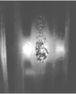
Skid flats are easily recognized by the damage zones at the same angular position on the tread of both wheels of a set. Figure 1 shows spalled out martensite from skid flats, the size of which did not exceed the size of the wheel/rail contact patch. The depth of martensite in these small skid flats was estimated to be about 0.5 mm.
Figure 1: Spalled out martensite from small skid flats on wheels from the same axle.
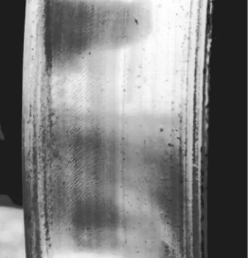
Historically, skid flats were considered to cause spalls while shells were the result only of contact fatigue [14]. The boundary is not so clear now since it is shown that cracks initiated by shallow martensite can propagate around the wheel circumference, leading to a fully shelled wheel. Figure 2 shows a shell propagating from the initial skid flat damaged region at the upper end of the affected zone.
1 Similarly, when a locomotive spins its wheels to start pulling a train, martensite will
Figure 2: Intermediate stage of shell growth from small skid flat.
Unfortunately, skid flat diagnosis is not always simple. Asymmetric skids flats may develop if skidding occurs in a curve with one in the flange root area with the other displaced towards the wheel rim. The different wear rates experienced at those two zones may allow one of the flats to wear away while the other develops into a shell. This can be distinguished from rolling contact fatigue where, if the wheel is not yet fully
shelled, contact fatigue cracks would be evident over the rest of the wheel.
Multiple skid flats are the result of stick-slip sliding which causes multiple small flats around the wheel circumference rather than a single large one. The flats are joined by a wavy ribbon of discolored metal. The same phenomena should appear on both wheels at the same angular position.
4. Rolling Contact Fatigue (RCF) Initiated Shells
4.1 Wheel/rail contact mechanics
The wheel/rail contact is often modeled using hertzian contact mechanics. Although the hertzian equations only hold for elastic contact, extensions have been made to allow for contacts with limited plasticity [6].
The load between a wheel and rail is assumed to be evenly distributed on each wheel of the car. For heavy haul operations, this gives a nominal 15 metric tonnes (16 tons, 33,000 lbs) load on each wheel against the rail. One should also bear in mind that irregularities in the rail (joints, rail shells etc.) or wheel (skid flats, shells, out of round) can lead to dynamic impact loading of the wheel (up to about 4 times the nominal load) [12].
This load is carried by a contact patch with area of about 100 mm2 (about the size of a Canadian or American dime). The contact geometry (i.e. wheel and rail profiles) is critical in determining the size and orientation of that patch. Geometry, load, creepage and material properties all influence the rate of contact fatigue.
4.2 Shakedown
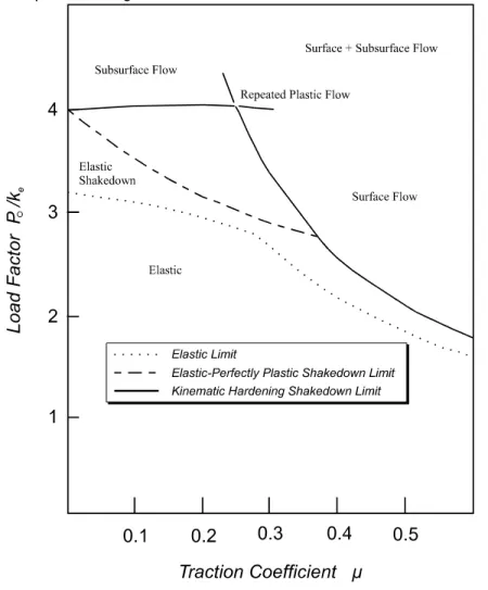
The shakedown diagram developed by Johnson [5] shows the relationship between traction, load and material strength (Figure 3). The traction coefficient (tractive force / normal load) is measured along the abscissa. The ordinate is a measure of the
maximum contact stress (Po) divided by the material yield in shear (k). One sixth of the
Vicker’s hardness provides a good numerical value of k.
Figure 3: Shakedown diagram
When the contact system operates in the region of repeated plastic flow, the material ratchets (i.e. incrementally flows) with each loading cycle [3]. As these tiny increments of plasticity accumulate, the steel’s ductility is eventually exhausted and a crack initiates. Because the most rapid ratchetting typically occurs at the surface, most contact fatigue cracks are surface cracks. This is the primary means of rolling contact fatigue.
Microcracks can also initiate at subsurface inclusions or voids in dirty steels and then coalesce along shear bands [4], nucleating a subsurface crack. When the wearing surface reaches these cracks, they can grow as any other contaminated surface crack.
5. RCF Crack Initiation
Combining the limits from the shakedown diagram with the hertzian relationship for elliptical contacts [6], we get ratchetting under the following conditions:
0
0 27
1
4
6
0 27
0 6
6
2 2 1 3 1 3 2 2 1 3 1 3< <
⎛
⎝
⎜
⎞
⎠
⎟ >
< <
⎛
⎝
⎜
⎞
⎠
⎟ >
µ
π
µ
µ
π
.
:
*
.
. :
*
/ / / /k
PE
R
k
PE
R
e e 1(a) 1(b)where µ is the coefficient of friction
k is the material’s shear strength
P is the normal load (including impact loads)
E* is an elastic property of the contacting materials (effective elastic modulus) Re is related to the contact geometry (effective radius)
R
R
R
R
R
e WT RT WL RL=
+
+
1
1
1
1
1
1
*
2where the T and L subscripts refer to the transverse and longitudinal directions, respectively.
Equation 1(a) describes a situation where maximum shear stress, ratchetting and crack initiation occur below the surface. In equation 1(b) the maximum values lie at the surface and can therefore be used to estimate the value of ratchetting and crack initiation at the wheel surface. Equation 1 shows that ratchetting will accelerate under the following conditions:
• High stress - increasing wheel loads (increasing P) or poor contact geometry (decreasing Re ) lead to increases in Po . Although increasing wheel loads are
continually sought by the industry for throughput reasons, the corresponding increases in contact stresses can be checked by controlling the contact geometry through rail grinding and wheel truing. Unfortunately, reverse curvatures on the rim side of the wheel (i.e. false flange) lead to localized high contact stresses.
Substituting the values RRT=203mm, RWL =457mm, RRL =∞ into Equation 1, shows that
a change in wheel transverse radius (RWT) from -305mm to +102mm increases the
contact stress (Po) by more than four times. Thus hollow wheels often show surface
cracking at the false flange. Wide track gauge exacerbates this problem by increasing the frequency of pummeling on that portion of the wheel.
Also, at the flange root/rail gauge corner, single contact point stress with a 44mm wheel flange radius on a 38 mm gauge corner radius gives stresses almost double those of the -305mm to 203 mm tread contact.
The use of a worn wheel profile will serve to reduce the gauge corner stresses, although care must be taken to ensure a minimum 6 mm radius difference in this location to avoid problems of corrugation and hunting associated with close conformity. Since the false flange which forms towards the end of the wheel truing interval is responsible for a disproportionate amount of wheel and rail damage, the rim side should be relieved to control the false flange development. Thus, more frequent truing of the wheel profiles could extend the wheel (and rail) life for a net economic benefit.
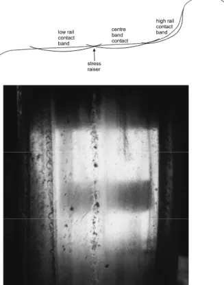
• Geometrical stress raiser - the stress will similarly increase significantly at the hump that sometime forms between running bands on the wheel tread surface. This is shown schematically and with a photograph in Figure 4. This phenomena tends to occur more often with self steering trucks which usually have two distinct tread running bands compared with the three to five bands with standard trucks. Contact with the hump region leads to high stresses which can initiate and propagate cracks.
Figure 4: Schematic of the formation of a geometrical stress raiser shown with a photograph of the crack propagation from such a stress raiser.
• Thermal Softening - At low values of k, the wheel/rail contact will more readily enter the region of incremental plasticity on the shakedown diagram. Under long
downgrade braking or when faulty brakes are continuously applied, a phenomena known as "hot wheels" occurs [8]. The resulting excessive tread surface
temperatures may lead to thermal softening of the wheel steels (i.e. decreases k) which, for the same contact geometry, results in a higher Po/k ratio.
• High Friction - Figure 3 shows that the shakedown limit at high friction declines as a function of (1/µ). High friction (µ>0.5) is especially likely to occur after rainfalls or periods of drifting snow when protective layers are washed from the wheel/rail interface.
6. Crack Propagation
Cracks are only dangerous once their size exceeds some threshold value beyond which their growth rate is extremely rapid, especially when compared with the relatively slow crack nucleation process [16]. Once the crack is nucleated, the sharp radius of its tip acts as a stress raiser, leading to a local plastic zone and further crack propagation.
Whatever the means of crack initiation, crack propagation is an RCF phenomena. Crack propagation is generally either by Mode I or Mode II stresses. Mode I is the crack
opening mode resulting from tensile stress at the crack tip. Mode II is propagation due to in-plane shear stresses. The exact mode of propagation in a given system may be any combination of these two and is dependent on the crack orientation, direction and magnitude of creepage, contact geometry and load values [10].
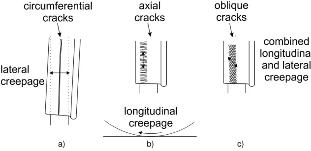
Stress cycling at the crack tip due to multiple rolling contact passes extends the crack in a direction perpendicular to the surface creepage (creepage is relative slip that occurs between two bodies in contact). Under any sort of braking or driving torque, there will be longitudinal (along the wheel circumference) creepage. Longitudinal creepage also develops due to insufficient rolling radii difference in mild curves. Lateral creepage results from an angle of attack between the rail and wheel which usually occurs during curving but may also be attributed to poor wheelset alignment or bolster friction which resists realignment after curves. Spin creepage is a result of tilt between the wheel axis and plane of contact and is usually controlled through profiling the wheel and rail. The relationship between creepage and crack propagation is illustrated in Figure 5.
a) b) c)
Figure 5: Cracks develop perpendicular to the direction of creepage. a)
circumferential cracks due to pure lateral creepage b) axial cracks due to pure longitudinal creepage c) oblique cracks due to combined lateral and longitudinal creepage
6.1 Crazing, micro-cracking and incipient shelling
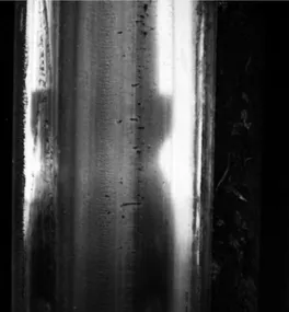
It can be difficult to assess visually whether surface cracks are destined to wear off or lead to shells. A system of minute cracks, referred to as surface crazing, which can be observed by the naked eye at close range, signals the onset of RCF crack initiation. Since photographs of crazing do not reproduce well, the reader is encouraged to observe this form of surface distress on their own. Figure 6 shows a shallow cracking system, referred to as micro-cracks which may or may not continue to propagate depending on the future wear rate and lubrication conditions encountered. Figure 7 shows a system of long, and deep cracks with incipient shells that is likely to lead to a
fully shelled wheel, very quickly if water is available (see Section 6.2). Dragging one’s finger “against the grain” may draw blood. Even under conditions of very high wear rate these will not usually wear away, since each rolling cycle which may wear away at the surface is also extending these cracks deeper into the surface.
Figure 6: Thin shallow cracks on the tread surface.
Figure 7: Cracked wheels show clearly defined failures repeated around at least most of the circumference.
6.2 Effect of Lubricants and Water
Lubricants and water can rapidly accelerate the propagation of surface cracks through two methods. Water may be drawn into the crack by capillary action whereupon the rolling compressive load closes the crack entrance and compresses the entrapped fluid. The crack tip tensile forces are considerably amplified and large mode I propagation rates result [2]. Lubricants are more viscous and don’t seep into the cracks as readily as water. They do, however, reduce the face friction and ease mode II propagation. Where there is no lubrication and crack face friction exceeds 0.4, mode II propagation is not a factor. This does not imply that lubrication should be avoided since it also reduces surface friction which in turn reduces the stresses which cause plastic flow. This in turn reduces and possibly eliminates surface crack initiation by ratchetting. Except through
skid flats, surface cracks would not initiate - hydraulic propagation would not be a consideration. Lubrication is therefore an important element affecting wheel life.
The worst problems therefore are likely to be encountered in systems which go through both dry and wet intervals where cracks are initiated in the dry periods and propagated during wet periods. In mild curves with predominantly longitudinal creepage due to insufficient rolling radii difference, it can be shown that moisture enhances hydraulic crack propagation in the field side of low rails and flange roots of wheels [7].
7. Magic Wear Rate
Once cracks form, there is only one process which can halt the inevitable march to shelling. Wear of the surface acts continually to remove material from the metal surface. If the wear rate is high enough to remove the damaged layer before the cracks can propagate, then shelling will be inhibited. There is therefore continuous competition between crack propagation and tread wear. If the wear rate is low, the wheel will eventually be removed for shelling. High tread wear rates necessarily lead to wheel failure from high flange. Maximum wheel life is achieved at the point where the wear rate is just sufficient to prevent cracks from reaching the critical length. This has been termed the Magic Wear Rate [7]. In cases where the wear rate is below the optimum level, “high wear” brakeshoes or carefully planned power braking can be employed to artificially achieve the same result.
8. Thermal Cracks
Thermal cracks are distinguishable in appearance from rolling contact fatigue by their length and orientation. Whereas contact fatigue cracks tend to be thin, long, and often angle to the circumference, thermal cracks show separation between the crack faces and are always axially oriented (Figure 8). Thermal cracks are due to the accumulation of thermal stresses from repeated cycles of heating and cooling such as occurs during hard braking. These cracks extend vertically into the surface material and will not propagate by rolling contact. They are therefore not an issue in shelling and are more important as an indicator of brake problems.
9. Shells
A wheel shell is perhaps the most obvious of the visible damage phenomena on the wheel tread surface. Shells are the result of crack propagation and applies to cracks initiated by either rolling contact fatigue or the breakage of martensite. Under many cycles of rolling contact, propagating cracks link beneath the surface, causing a large pit of material to spall off. Under continued loading, the crack system may propagate the entire circumference of the wheel. Once a wheel is fully shelled (Figure 9), it is difficult to determine whether it was initiated by martensite or rolling contact fatigue. The intense pummeling that the shelled zone undergoes usually wipes out all traces of cracking that led to the shell formation and similarly the martensite has cracked away. The presence of martensite in a shelled zone does not imply skid flats since strain martensite (see Section 3) can form after shells develop from rolling contact fatigue.
Figure 9: A fully shelled wheel.
10. Interpreting Wheel Defects
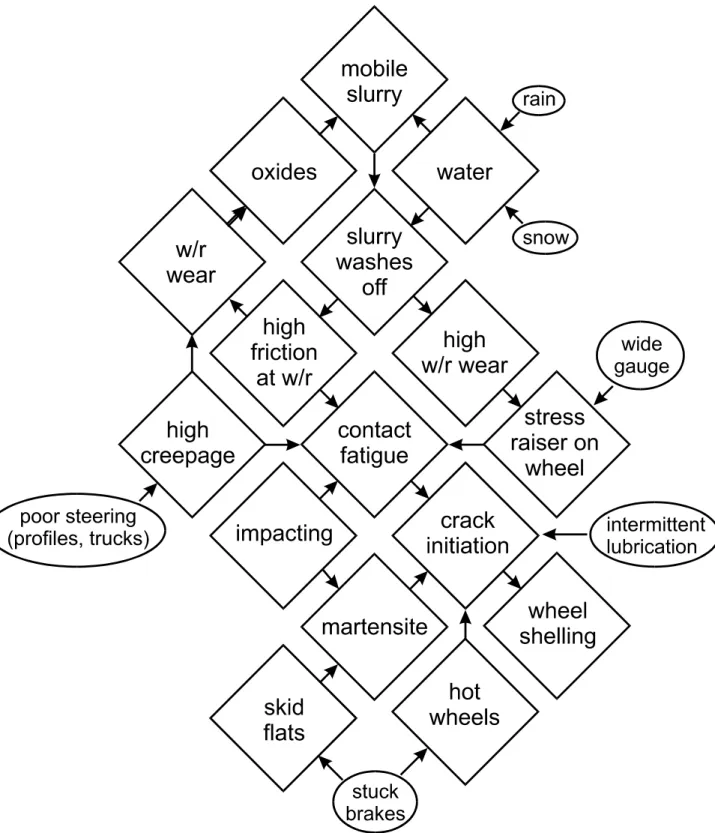
Table 1 summarizes the relationship between crack orientation and operational parameters, as explained in Section 6. The most important factors related to wheel shelling are summarized in Table 2 and the relationships shown graphically in Figure 10.
Table 1: Relationship between crack direction, creepage and operating parameters. Causes of wheel shelling
crack orientation creepage diagnosis
axial longitudinal large portion of time braking insufficient rolling radii difference circumferential lateral poor curving
check profiles for hollow wheels excessive bolster friction
poor truck condition oblique combined lateral
and longitudinal
combination of above
metallurgical phenomenon
physical condition
probable cause
martensite skid flats stuck brakes multiple skid flats dragging brakes contact fatigue high friction
with large creepage
dry rail, inadequate tread “contamination” large angle of attack on non-steerable trucks inappropriate wheel/rail profiles
high stress excessive static wheel loads, dynamic overloading
non-conformal wheel/rail profiles external stress raisers: ridges on tread
surfaces formed mostly with steerable trucks or running on false flange of hollow wheels
internal: inclusions in dirty steels low strength hot wheels - thermal softening
low hardness steels
moisture accelerates propagation of surface cracks formed during previous dry periods
Figure 10: Relationship between shelling and various operating and environmental parameters
11. Concluding remarks
The causes of wheel shelling can be classified into two categories. Martensite formed at skid flats is responsible for initiating a network of cracks as the brittle material crumbles from the affected zone, also leading to high impact forces. Rolling contact fatigue (RCF) is responsible for initiating the remaining cracks. RCF is the result of many cycles of contact stress (Po) which exceed the shakedown limit. Based on equation 1,
maintenance of the wheel/rail system for wheel shelling should consider the following parameters:
• Contact geometry (Re) - can be controlled by rail profile grinding and wheel turning to
a worn profile. Wheel diameter is usually not as significant as the transverse profile. Geometrical stress raisers such as the true tracking hump should be eradicated. Since a false flange is almost inevitable by pummeling considerations, the incidents of wide gauge in curves and/or of undue railhead plastic flow into the field side of the low rail should be minimized. This should reduce the frequency of contact between the low rail and wheel’s false flange and the associated initiation of surface cracks. • Friction coefficient (µ) can be controlled through the application of friction modifiers.
Ensuring that friction doesn’t exceed about 0.4 will minimize excessive ratchetting. • Contact load (P) is usually fixed by the load but operators should seek to eliminate dynamic loads on the wheel commonly encountered at welded rail joints and other discontinuities in the rail structure.
• Reduction in shear strength (k), caused by thermal softening could best be avoided by ensuring that there are no dragging brakes. This means that brake pipes must be fully charged in all of the train, even in mid-winter cold weather.
• Creepage is generally a function of the wheel and rail profiles and the type of truck and its quality of maintenance. Poor steering that results from some profiles gives excessive lateral creepage in curves and hunting in tangent track. Poor truck rigidity may allow warpage which causes the truck to travel crabwise down the track. Excessive bolster friction will inhibit steering in curves and realignment in tangent track.
12. References
1. Field Manual of the AAR Interchange Rules, Association of American Railroads, Washington, 1992
2. A. F. Bower, “The effects of crack face friction and trapped fluid on surface initiated rolling contact fatigue cracks”, University of Cambridge Technical Report, CUED / C-Mech / TR.40 (1987)
3. A.F. Bower and K.L. Johnson, “Shakedown, residual stress and plastic flow in repeated wheel-rail contact”, Rail Quality and Maintenance for Modern Railway Operation, J.J. Kalker, D.F. Canon and O. Orringer, Eds., Kluver Academic Publishers (1993) 239-252
4. C.G. Chipperfield and D.H. Skinner, “A study of subsurface fatigue in rails”, Railway Engineering Conference, Sydney, September 1981
5. K.L. Johnson , “The mechanics of plastic deformation of surface and subsurface layers in rolling and sliding contact”, Material Science Forum: the role of subsurface zone in wear of materials, R. Solecki, Ed., Trans. Tech. Publications (1988) 33-40 6. K.L. Johnson, Contact Mechanics, Cambridge University Press, England, 1985 7. J. Kalousek, “Magic wear rate and contact fatigue”, Section 7.3, Session VII, Rail
8. J. Kalousek, J.H. Hornaday and W.N. Caldwell, “Wheel shelling problems on the Canadian National Railway’s British Columbia Northline”, Proceedings of the 9th International Wheelset Congress, Montreal, Canada, Sept. 1988
9. T. Kigawa and E.Kimoto, “Influences of skidding pattern upon the occurrences of skid damage to railway wheels”, Wear Vol. 167, pg. 143-154, 1993
10. R. Lunden, “Cracks in railway wheels under rolling contact load”, Tenth International Wheelset Congress, Sydney, Australia, 1982
11. J.Rismantab-Sany, G.J. Moyar, B. Rajkumar, “Dynamics of freight car wheelset slip and tread temperature”, RTD-Vol. 5, Rail Transportation, ASME 1992
12. J.F. Scott, “Evaluation of Concrete Turnout Ties and Bridge Ties”, AREA Annual Conference, Chicago, March 1986
13. J. Slaba, Railway wheel defect study”, Transportation Development Center, CIGGT-PRO-067, Canada, 1992
14. D.H. Stone, B.R. Rajkumar, S.M. Belport, K.L. Hawthorne and G.L. Moyar, “Theoretical and experimental study of wheel spalling in heavy haul hopper cars”, Tenth International Wheelset Congress, Sydney, Australia, 1982
15. M.A. Tanvir, “Temperature rise due to slip between wheel and rail - an analytical solution for hertzian contact”, Wear, 61 (1980) 295-308
16. T. Yoshioka and T. Fujiwara, “The crack growth rate in rolling contact fatigue process is very fast”, Wear, 113 (1986), 291-294


![[PDF] Base de données relationnelle Access concepts de base - Cours Access](data:image/gif;base64,R0lGODlhAQABAIAAAP///wAAACH5BAEAAAAALAAAAAABAAEAAAICRAEAOw==)