HAL Id: hal-01315225
https://hal.archives-ouvertes.fr/hal-01315225
Submitted on 12 May 2016
HAL is a multi-disciplinary open access
archive for the deposit and dissemination of
sci-entific research documents, whether they are
pub-lished or not. The documents may come from
teaching and research institutions in France or
abroad, or from public or private research centers.
L’archive ouverte pluridisciplinaire HAL, est
destinée au dépôt et à la diffusion de documents
scientifiques de niveau recherche, publiés ou non,
émanant des établissements d’enseignement et de
recherche français ou étrangers, des laboratoires
publics ou privés.
Theoretical studies and simulation of graded index
segmented LiNbO 3 waveguides for quantum
communications
O Danila, Marc de Micheli, P Aschieri, P Sterian
To cite this version:
O Danila, Marc de Micheli, P Aschieri, P Sterian. Theoretical studies and simulation of graded
index segmented LiNbO 3 waveguides for quantum communications. Optoelectronics and Advanced
Materials - Rapid Communications, INOE Publishing House, 2012, 6 (1-2), pp.40-43. �hal-01315225�
Theoretical studies and simulation of graded index
segmented LiNbO
3
waveguides for quantum
communications
O. DANILA*a, M. DEMICHELIb, P. ASCHIERIb, P. STERIANa
aPolytechnical University of Bucharest, Faculty of Applied Sciences, 060082, Bucharest, Romania b
Laboratoire Physique de Matière Condensée, UMR 6622, Nice Cedex 2, France
The present paper focuses on the theoretical characterization and simulation of different graded index segmented LiNbO3
waveguides. Several dependencies of the refractive index versus the z direction of propagation of the applied laser field are examined and a comparative discussion is made, taking into account dispersive and attenuation losses.
(Received November 22, 2011; accepted February 20, 2012)
Keywords: Quantum electronics, Quantum communications, Segmented waveguide, Graded index waveguide
1. Introduction
Quantum waveguides [1-5] play an important role in the coherent control of injected light, the efficiency of these guides being always a subject of improvement. Guiding light is greatly exploited by optical and quantum communication [2, 7-12]. Nonlinearities that appear in the waveguides are of great use in second-order susceptibility applications such as sum and difference frequency generation [1, 2]. Periodically poled lithium niobate waveguides [4] have the ability to generate entangled photon pairs with a very good efficiency – albeit that improvements can be done in order to reduce input power – which play an imperative role in quantum sources and quantum repeater schemes [1-4]. The paper is divided into four sections: the introductory section, where an outline of the recent progresses is discussed. Part two represents the theoretical section, in which the model and equations that lead to the simulations are shown. In the third section, the simulation and results section are presented and discussed comparatively. Conclusions are drawn in the fourth section.
2. Theoretical model
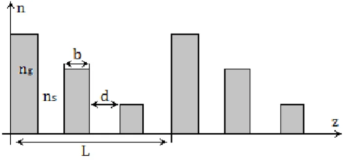
The theoretical model of the waveguide takes into consideration a slab z-cut waveguide that has a periodical segmented index profile as shown in Fig. 1. The z direction index profile of the guide is considered independent of the other directions, for the simplicity of the calculus.
Fig. 1. Refractive index vs. field propagation direction, with b – thickness of the guiding index region, d – thickness of the substrate index region, L – period of segmentation, ng – guiding refractive index and
ns – substrate refractive index.
The index model follows the equivalent guide model [6, 13-14] given by the relation
(
)
equiv g g sb
n
n
n
n
(2.1) whered
is the duty cycle of the segment period, ng therefractive index of the segment and ns the index of the
substrate.
This approach treats the segmented waveguide as a continuous one, but with a refractive index equal to nequiv. The duty cycle is kept constant throughout the guide. However the segment index will be considered variant with respect to z:
0
( )
g gTheoretical studies and simulation of graded index segmented LiNbO3 waveguides for quantum communications 41
where ng0 is the effective refractive index of the segment and
f(z) is a continuous weight function that describes the
modulation and averaging of the refractive index throughout the waveguide. The simulations will consider the averaging function as well as some continuously variable functions in order to establish a comparison basis.
The weight function is specifically modeled in order to assure the modulation. Boundary conditions, together with the linearity of the profile, dictate that the continuous unmodulated function of Fig. 1 is
( ) 1
f z mz (2.3) where m is the slope of the refraction index, or modelling parameter. Modulation of this function is done by averaging the weight function over the guiding regions of one period. The length of one period is divided into an equal number of guiding and substrate regions:
( )i
i
L
b d (2.4)and therefore, the average refractive index over one guiding region is ( ) ( ) 0 ( ) ( )
( ) d
d
i b d b i b d gi g i b d b i b df z
z
n
n
z
(2.5)thus, the refractive index taken over all of the guided regions being the average of all independent indices:
( ) gi i g i n z n i
(2.6)Substituting (2.6) in (2.1) will yield the equivalent refractive index. As an observation, it should be noted that the modelling function can take a user-defined form, each function leading to a different waveguide behavior towards the same applied field.
The electric field inside the waveguide respects the Helmholtz equation [5]
2
E
k E
20
(2.7) where k is the wave number of the applied field. As it is known, the refractive index is the velocity rapport given by:phase
c ck
n
v (2.8) Substituting the last equation into (2.7), we have
2 2 2 2 0 n E E c (2.9) We shall make the further assumption that the component E (x, y) is a slowly variable function and therefore can be perceived as a constant.
Furthermore, the wave is assumed to propagate independently on the three axes, therefore Eq. (2.9) can be rewritten as only a z – direction variation:
2 2 2 2 2 d 0 d E n E z c (2.10) Solutions of the trivial equation (n (z) = ct.) are a sum of sine and cosine functions that propagate throughout the waveguide. However, when the refractive index varies with the propagation direction, the profile of the electric field changes, as we will show in Section 3.
Power losses occur from attenuation and dispersion effects in the material. Attenuation effects will be discussed by directly evaluating the intensity graphs in the propagation direction. Dispersion effects come into play when perturbations in the refractive index value of the waveguide occur. Such perturbations will depend on the other propagation directions n = n (x, y, z).
For simplicity, we shall only evaluate the n = n (x, z), as a step discontinuity of the value. To evaluate this phenomenon, we shall consider the field component of the form [3] i i ( ) ( , ) gz ( ) ( , ) dzd g g d d d E A z u x y e B z u x y e
(2.11)where Ag (z), Bd (z) are the amplitudes of the guided and
dispersive modes in the direction of propagation,
g,
dthe propagation constants in the guided and dispersive modes and
u u
g,
d the normalized transversal guided and dispersed fields on the directions perpendicular to the propagation direction. For simplicity, we shall consider a one-dimensional dependency of the guided and dispersive modesu x u x
g( ),
d( )
.Substituting (3.2) into (2.10), and multiplying by
u
d*, after some mathematics and second derivative negligible approximations, the resulting equation isi * 0 d i ( , ) ( ) ( ) d d 2 z d g eq g d B A n e n x z u x u x x z
(2.12)where
0 the void electrical permittivity,n
eq the equivalent refractive index,
g d the propagation constant difference between the guided and the radiant modes, and
n x z
( , )
the refractive index perturbation. The field functions will be taken as [3]( )
cos(
)
g g
u x
k x
,u x
d( )
cos(
k x
d)
(2.13) For the simplicity of the calculus, we shall consider the perturbations to be localized to certain points of the material, and having step index differences. Perturbations in the z direction shall not be taken into consideration, thus the refractive index perturbation can be written as( , ) ( p)
p
n x z x x
(2.14) with
(
x
x
p)
n
p. Solving Eq.(3.3), with these considerations yields i sin( ) sin( ) ( ) 4 2( ) 2( ) g g d g d z d p p g d g d A k k k k B z n e k k k k
(2.15)The radiative power is given by the relation
( ) d
d d
P B z z
(2.16) Integration will be taken over the width W of the sample, therefore, the radiative dissipated power is given by 2 2 2 2 sin( ) sin( ) 8 2( ) 2( ) g g d g d d p p g d g d A W k k k k P n k k k k
(2.17)3. Simulations and results
Solving Eq. (2.10) for the discussed modelling parameters yields the graphs shown below (Fig. 2):
Fig. 2. The electric field and intensity profiles through the z direction of the waveguide. The waveguide parameters are: length L30 m, maximum indices difference n ng0 ns 0.085, pump wavelength
1560 nm,
and modelling parameter 5
0.7 10 . m The number of segments have been chosen to be: a) n = 2, b) n = 5.
Discretization of the waveguide profile with the use of the integral averaging function does not change the wavefront form in the waveguide.
However, the effective refractive index can be modelled by varying the modelling parameter to achieve the desired output intensity and the number of guiding regions to control the field and intensity frequencies.
Simulations were carried out for the continuously varying refractive index n = n(z), using the Coupled-Mode Theory (CMT) [3] approach.
In this picture, Eq. (2.10) changes to the following:
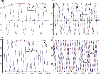
2 2 2 2 2 d ( ) ( ) ( ) 0 d E z n z E z z c (3.1) Solving (3.1) for different gives the field and intensity profile, seen in Fig. 3 and Fig. 4:
Fig. 3. Electrical field and intensity profiles for continuously varying refractive index. Comparison between: a): linear n z( ) 1 mz and exponential
( ) exp( )
n z mz dependencies; b): linear and square root n z( ) m z dependencies.
Fig. 4. Electrical field and intensity profiles for continuously varying refractive index. Comparison between linear and hyperbolic n z( ) 1
mz
– dependencies. The length of the
guide is taken as such as it exhibits the rise in the hyperbolic dependency.
Dispersive spectral power losses are calculated using Eq. (2.17), and are normalized by a factor given by the sinus coefficients in (2.17):
Fig. 5. Normalized radiative power as a function of the propagation number sum and difference between the
Theoretical studies and simulation of graded index segmented LiNbO3 waveguides for quantum communications 43
4. Discussions
As it can be seen from Fig. 3, the linear field dependence exhibits an attenuation over small (105 order) distances. The exponential dependence, however, shows an amplitude increase over the same distance. Real experiments will conclude that this increase will be saturated at the maximum pump power. The root dependence of the refractive index shows an increase in field frequency, with an overall attenuation of the field. Fig. 4 shows the behavior of the linear and inverse linear dependences over a guide length comparable to achievable dimensions with the current technology. In the linear case, we can observe a preservation of the electric field and intensity amplitude, but an overall modulation of the signal occurs. Inverse linear dependence shows a great increase in the amplitudes, the overall modulation of the signal still remaining present.
Power attenuation considerations can be drawn from the graphs above. For some dependencies, the intensity
( )
I z
decreases swiftly, over guide lengths of several micrometers. In other cases, the intensity increases, with oscillations, to a saturation, the medium contributing to the amplification of the radiation. To this effect, we highlight the inverse and exponential dependencies of the refractive index.5. Conclusions
In this paper we have investigated the behavior of lithium niobate waveguides with a graded refractive index on the field direction of propagation. Using the equivalent guide model, different dependencies were simulated at microscopic and macroscopic lengths, yielding different behaviors over the appreciated distances. A signal modulation appears in the case of linear and inverse linear modulation, the frequency being dependent on waveguide parameters. We can therefore assume that information can be encoded on the incident wave by using the waveguide, and if successfully controlled, the waveguide can be treated as either an amplitude or a frequency modulator, depending on the different dependence.
References
[1] A. Ghatak, K. Thyagarajan: Optical Electronics, Cambridge University Press, Cambridge, (1989). [2] A. Yariv, Quantum Electronics, 4th Edition, Wiley &Sons, Florida, (1989).
[3] P. Aschieri, Etude numérique et expérimentale des guides d’ondes segmentés, Ph. D. Thesis, Nice, (1999). [4] S. Tanzilli, W. Tittel, H. De Riedmatten, H. Zbinden, P. Baldi, M. DeMicheli, D.B. Ostrowsky, N. Gisin: PPLN Waveguide for Quantum Communication, European Journal of Physics D, 18(2), (2002).
[5] J. Liu, Photonic Devices, Cambridge University Press, Cambridge, (2004).
[6] J. D. Bierlein, Propagation in Segmented Waveguide Structure, Quantum Electronics and Laser Science, 13, (1992).
[7] A. R. Sterian, Coherent Radiation Generation and Amplification in Erbium Doped Systems, Advances in Optical Amplifiers, Paul Urquhart (Ed.), ISBN: 978- 953-307-186-2, InTech, Vienna, (2011).
[8] A. D. Petrescu, A. Sterian, P. E. Sterian, Editor(s) Gervasi, O., Gavrilova ML., Computational Science and its Applications - ICCSA 2007, Pt 1, Proceedings 4705450-461, (2007).
[9] A. Sterian, Computer modelling of the coherent optical amplifier and laser systems, Editor(s): Gervasi, O; Gavrilova, ML., Computational Science and its Applications - ICCSA 2007, Pt 1, Proceedings 4705436-449, (2007).
[10] C. Iliescu, M. Avram, B. Chen, et al., J. Optoelectron. Adv. Mater. 13(2-4), 387 (2011).
[11] B. Lazar, P. Sterian, J. Optoelectron. Adv. Mater. 13(1-2), 32 (2011).
[12] M. Dima, M. Dulea, D. Aranghel et al., Optoelectron. Adv. Mater. – Rapid Commun. 4(11), 1840 (2010).
[13] Z. Weissman, A. Hardy, Modes of Periodically Segmented Waveguides, Journal of Lightwave Technologies, 11, (1993).
[14] K. Thyagarajan, V. Mahalakashmi, M. R. Shenoy, Propagation Characteristics of Planar Segmented Waveguides with Parabolic Index Segments, Optical Letters 19, (1994).
_______________________
*