HAL Id: hal-01524992
https://hal.archives-ouvertes.fr/hal-01524992
Submitted on 19 May 2017
HAL is a multi-disciplinary open access archive for the deposit and dissemination of sci-entific research documents, whether they are pub-lished or not. The documents may come from teaching and research institutions in France or abroad, or from public or private research centers.
L’archive ouverte pluridisciplinaire HAL, est destinée au dépôt et à la diffusion de documents scientifiques de niveau recherche, publiés ou non, émanant des établissements d’enseignement et de recherche français ou étrangers, des laboratoires publics ou privés.
Radiation Efficiency Improvement of a Balanced
Miniature IFA-Inspired Circular Antenna
François Sarrazin, Sylvain Pflaum, Christophe Delaveaud
To cite this version:
François Sarrazin, Sylvain Pflaum, Christophe Delaveaud. Radiation Efficiency Improvement
of a Balanced Miniature IFA-Inspired Circular Antenna. IEEE Antennas and Wireless
Prop-agation Letters, Institute of Electrical and Electronics Engineers, 2016, 16, pp.1309-1312. �10.1109/LAWP.2016.2633308�. �hal-01524992�
Abstract—The radiation efficiency improvement of an
Electrically Small Antenna is presented. We consider a balanced Miniature IFA (Inverted F-Antenna)-Inspired Circular Antenna (MIICA) whose radius is / at 433 MHz and radiation efficiency is 30 %. By modifying the antenna strip width, we identify, by electromagnetic simulations, an antenna radiation efficiency improvement up to 53 % while keeping its overall dimension and general structure identical. Then, we confirm the antenna performances improvement by radiation efficiency measurements performed inside a large anechoic chamber and using the gain pattern integration technique. An optical fiber link is used to avoid possible perturbation due to the feeding coaxial cable. The radiation efficiency improvement, confirmed by experimentation, is of major interest for Ultra NarrowBand antennas for which the radiation efficiency is the most critical parameter. This efficiency improvement is discussed in light of the fundamental limits of miniature antennas.
Index Terms— electrically small antenna, Inverted-F Antenna,
radiation efficiency, Ultra NarrowBand antenna, balanced antenna measurement
I. INTRODUCTION
LECTRICALLY small antennas (ESAs) have been studied for
many years. Indeed, it is a key element for radio communication systems miniaturization and small antenna design is still very challenging. ESA limits have been first studied in the mid-20th century by Wheeler [1]-[2] who
considered an antenna electrically small if 0.5, where is the wavenumber and is the radius of the minimal sphere enclosing the antenna. The fundamental limitation introduced by Chu [3], and confirmed later by McLean [4] showed that the Q-factor of a single resonance antenna is lower bounded by its size as + = rad 3 Chu ( ) 1 1 ka ka Q η (1)
where is the antenna radiation efficiency. Since the Q-factor of a narrowband antenna is inversely proportional to its bandwidth [5]-[6], (1) highlights the classical tradeoff between radiation efficiency, size and bandwidth. Several studies focus
This work was supported in part by the French Research Agency (ANR) under the “SENSAS” project (ANR-13-INFR-0014).
on enlarging the bandwidth (minimizing the Q-factor) of ESAs for a given size. This can be done for example by modifying the antenna structure [7] or making the antenna frequency-agile by using active components [8]. However, for some specific applications, only a narrow frequency bandwidth is necessary. Indeed, as part of a Wireless Sensor Network, a utility meter or a traffic sensor only needs to transmit intermittently and only a few of packets of data [9]. Moreover, the available power of the communication node is usually very low. Thus, the radiation efficiency becomes the most critical parameter of the required antenna. This leads to the novel concept of Ultra NarrowBand (UNB) antenna [10].
In this context, we present the radiation efficiency optimization of a balanced Miniature IFA-Inspired Circular Antenna (MIICA) (Fig. 1). The main objective of this paper is to demonstrate how to improve the radiation efficiency of an ESA while keeping its general design and overall dimensions identical. The initial idea is to reduce the ohmic losses of the antenna by enlarging its strip width. It is interesting to notice that the radiation efficiency improvement occurs because the considered antenna is electrically small (radius smaller than /28). Indeed, there is no such effect when dealing with compact or large antenna ( /10).
Impedance measurements are performed using a differential setup [11] to avoid classical asymmetric measurement issues like leakage current flowing back on the coaxial cable shield which skews the measured results [12]. Radiation efficiency measurements are made inside a large anechoic chamber using the gain pattern integration technique, still using a differential
The authors are with the Laboratory of Antenna and Propagation, CEA-LETI/DSYS/STSF (e-mail: christophe.delaveaud@cea.fr)
Radiation Efficiency Improvement of a
Balanced Miniature IFA-Inspired Circular
Antenna
F. Sarrazin, S. Pflaum, and C. Delaveaud
E
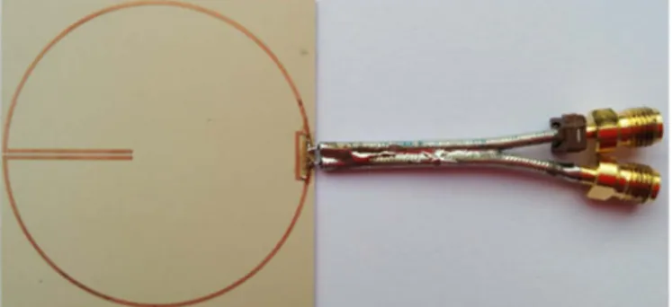
Fig. 1. Realized prototype of the considered MIICA fed by two coaxial cables terminated by SMA connectors.
setup [13]. Moreover, an RF to optical transducer as well as an optical fiber link [14] is used to connect the measured antenna to the VNA in order to avoid perturbation due to the feeding coaxial cable.
First, the MIICA as well as the differential impedance measurement setup are introduced in section II. Then, section III presents the radiation efficiency optimization and improvement of the MIICA while keeping the same overall dimension. Effects on the antenna Q-factor are also discussed. Radiation efficiency measurement setup and results that confirm the efficiency improvement are presented in section IV. A conclusion ends this paper.
II. MINIATURE IFA-INSPIRED CIRCULAR ANTENNA
We consider the antenna presented in Fig. 1 designed to operate at 433 MHz ( = 70 cm). It is a balanced Miniature IFA-Inspired Circular Antenna (MIICA) printed on low loss dielectric substrate. This antenna combines different miniaturization techniques. The first is related to the presence of a short circuit recalling a quarter wavelength IFA structure. Then the quarter-wave arm is folded along circular shape. Finally, a capacitive load is introduced at the antenna extremity to artificially elongate the resonant length. This capacitor is constituted of a coplanar twin strip line whose length adjusts the capacitance value. The antenna radius is 25 mm (λ/28 at the working frequency or = 0.2267) and the capacitor is 20.4 mm long. The short circuit strip used for impedance matching is 8 mm long and located 2 mm away from the feed. The copper strips width is 0.6 mm and the substrate is a 0.8 mm thick Rogers RO3003 ( = 3). This antenna is simulated with ANSYS HFSS [15] using a lumped port located between the two antenna arms. The simulated radiation efficiency is equal to 30 % at 433 MHz.
Feeding balanced antennas with a single unbalanced coaxial cable can lead to inaccurate results, mainly due to leakage current flowing back on the cable shield which can drastically change both impedance and radiation characteristics of electrically small antennas [12]. A possible solution is to use a balun that forces opposite currents in each antenna arm. However, the quality of the balun can drive the measured antenna performances. Here, we use a differential measurement technique [11] based on the association of two coaxial cables. Each core is connected to one antenna arm and the two shields are soldered together as showed in Fig. 1. On the other side, the coaxial cables are terminated by female SMA connectors to be connected to the Vector Network Analyzer (VNA). First, the VNA is calibrated in a classical way using a Short-Open-Load-Through calibration procedure. Then, in order to perform the de-embedding of the two small coaxial cables, their S-parameters are measured when terminated by a short-circuit and a 50 Ω load. The S-parameters of one cable are deduced from this measurement by assuming that they are the same length. Finally, the S-parameters of the whole system (cables and antenna) are measured. From these measurement and using abcd-matrices, we obtain the S-parameters of the antenna alone and its input impedance can be computed as [11]
21 12 22 11 22 11 21 12 0 diff ) 1 )( 1 ( ) 1 )( 1 ( 2 S S S S S S S S Z Z − − − − − − = (2)
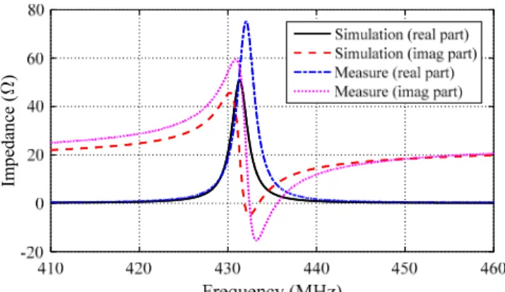
where is the characteristic impedance of the feeding coaxial cables (50 Ω). The simulated and measured input impedances of the MIICA are presented in Fig. 2 as a function of the frequency. We can notice that the antenna input impedance presents an antiresonance at 433 MHz. The reflection coefficients are shown in Fig. 3 as a function of the frequency. This measurement is in very good agreement with the simulation results using a lumped port. Moreover, the antenna is correctly matched to 50 Ω with a 1.5 MHz bandwidth (| | < −10 dB), i.e. a 0.35 % relative bandwidth.
III. RADIATION EFFICIENCY OPTIMIZATION
In this part, we focus on the radiation efficiency optimization of the MIICA while keeping its overall dimension the same. The idea here is to reduce the antenna losses due to the limited conductivity of the coppered strip by enlarging the strip width. The loss resistance R of a classical wire dipole antenna can illustrate the strategy. Indeed, if we consider a sinusoidal current distribution along a dipole antenna, its loss resistance can be simplified as σ ωμ π δ π σ2 4 2 2 1 0 r l r l Rloss = = (3)
Fig. 2. Simulated and measured input impedance of the MIICA. Im pe da nc e ( )
Fig. 3. Simulated and measured reflection coefficient of the MIICA.
S 11
(d
where l is the dipole length, σ is the conductivity of the metal, r is the wire radius and δ is the skin depth defined as δ =
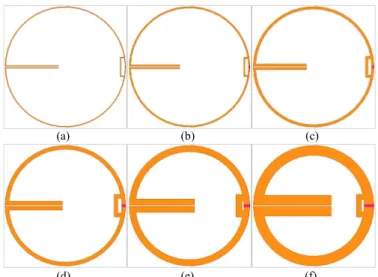
2/ μ ωσ with μ the permeability of free-space and ω the angular frequency. Thus, increasing r implies reducing R and so increase the antenna radiation efficiency. This parameter has usually few influence on the efficiency of electrically large antenna but we suggest here to study it in the particular case of ESA. Ten different strip widths from 0.1 mm to 4.1 mm are considered and six of them are presented as illustration in Fig. 4. It has to be noticed that the antenna outer diameter is kept constant to 50 mm whatever the strip width. Since the strip width modification implies a frequency shift, the linear capacitor length is tuned to keep the resonant frequency the same and equal to 433 MHz. This is the only geometrical modification of the antenna in relation to the change of the strip width.
The simulated radiation efficiency is presented in Fig. 5 as a function of the strip width. It rises from 18 % for the thinnest strip (0.1 mm), up to 53 % for the thickest one (4.1 mm). We show here that it is possible to increase (decrease) the radiation efficiency of an ESA by simply enlarging (shrinking) its strip width, and thus without modifying its overall structure and maximum dimension. Indeed, increasing the strip width tends to decrease the ohmic losses inside the antenna structure. As a result, the radiation resistance is increased and so the radiation efficiency. Such an effect cannot be seen when dealing with compact antennas since the ohmic resistance is usually very low, even for small radius (radiation efficiency close to 100 %). Also, we can see in Fig. 5 that 53 % seems to be the radiation efficiency upper bound that can be reached for this antenna structure, as the radiation efficiency does not really improve between 3.1 mm and 4.1 mm. Moreover, if we consider a strip width larger than 4.1 mm, some parasitic effect appears between the short circuit and the load capacitor as they come very close and the antenna behavior is altered. These parasitic effects contribute to the physical limitation observed in the antenna performances.
The simulated Q-factor of the MIICA, computed with the Yaghjian and Best formula [6], is presented as a function of the
strip width in Fig. 6. As the radiation efficiency, the Q-factor increases according to the antenna strip width. Thus, it respects the tradeoff between radiation efficiency and bandwidth for a given size as highlighted in (1). This is confirmed in Fig. 7 where the radiation efficiency to Q-factor ratio appears relatively stable as a function of the strip width although it seems maximum for 3.1 mm.
IV. RADIATION EFFICIENCY MEASUREMENT
A. Measurement setup
The antenna radiation efficiency is a very convenient parameter to evaluate miniature antenna performances since it
(a) (b) (c)
(d) (e) (f)
Fig. 4. MIICAs designed with six different strip widths (a) 0.3 mm, (b) 0.6 mm, (c) 1 mm; (d) 1.6 mm, (e) 2.6 mm and (f) 4.1 mm.
Fig. 5. Radiation efficiency of the MIICA as a function of the strip width, simulated and measured in the anechoic chamber.
0 0.5 1 1.5 2 2.5 3 3.5 4 4.5 0 20 40 60 80 Strip width (mm) R ad iat io n eff ici en cy (% ) Simulation Measure
Fig. 6. Simulated and measured Q-factor of the MIICA as a function of the antenna strip width.
0 0.5 1 1.5 2 2.5 3 3.5 4 4.5 100 150 200 250 300 350 Strip width (mm) Q -fact o r Simulation Measure
Fig. 7. Simulated and measured radiation efficiency to Q-factor ratios of the MIICA as a function of the antenna strip width.
0 0.5 1 1.5 2 2.5 3 3.5 4 4.5 1 1.5 2 2.5x 10 -3 Strip width (mm) E ffi ci en cy /Q -f act o r Simulation Measure
describes how well an antenna radiates the power accepted at its feed. It is classically obtained by integrating the antenna gain pattern over the whole sphere. This measurement is performed in far field inside the large anechoic chamber of the CEA-LETI (20 m long, 12 m high and 12 m width) that is well operating starting from 100 MHz. As the antenna radiates with an omnidirectional pattern, specific precautions are taken to not disturb its radiation. The antenna support (6 m high) is made of foam and the antenna is connected to a compact RF to optical transducer. The measured data is then sent to the VNA through an optical-fiber link [14]. The antenna gain is obtained using the comparison method [16] with a known reference antenna (SH400 horn antenna from SATIMO). As for the impedance measurement, a differential setup is used (Fig. 1). The gain radiation pattern is thus measured in two steps. First, the gain radiation pattern is measured on the port 1 while the port 2 is terminated by a 50 ohms load. Second, the two ports are inversed and a second measure is performed. The differential gain pattern is then computed from both measurements [13]. As ESAs present quasi-omnidirectional radiation pattern, the measurement of the gain is needed for a limited number of cutting planes.
B. Results
To validate the radiation efficiency optimization presented in the previous section, three antenna prototypes have been realized. Their strip widths are equal to 0.6 mm (Fig. 8-left), 1 mm (Fig. 8-center) and 1.6 mm (Fig. 8-right). These antennas have been first measured in terms of input impedances using the setup presented in section II. Although not shown here for brevity, the simulated and measured input impedances are in very good agreement (example of comparison in Fig. 1 and Fig. 2). The gain radiation patterns of these antennas have then been measured inside the anechoic chamber. Measured antenna radiation efficiencies are compared to the simulation results in Fig. 5. They are equal to 28 %, 32 % and 39 % for antennas whose strip widths are 0.6 mm, 1 mm and 1.6 mm, respectively. The measured radiation efficiencies are slightly underestimated (2 % to 6 % lower) compared to the simulated values for the three antennas. This is attributed to classical gain measurement uncertainties. Thus, the radiation efficiency improvement of the MIICA, by enlarging its strip width, is validated by the measurement. Measured Q-factors are compared to the simulated ones in Fig. 6. As for the radiation efficiency, measurements are slightly lower than the simulation results proving the presence of additional losses in experiment. Finally, the measured radiation efficiency to Q-factor ratios are
compared to the simulated results in Fig. 7. Measurement and simulation results are in very good agreement and this ratio is quasi-constant as a function of the strip width. This confirms the tradeoff between the antenna radiation efficiency and its bandwidth.
V. CONCLUSION
A novel balanced Miniature IFA-Inspired Circular Antenna (MIICA) that presents small size (radius of λ/28 at 433 MHz) and good radiation efficiency (up to 53 % in simulation for the thickest strip), is introduced. We showed that this ESA’s radiation efficiency can be tuned from 17 % to 53 % by modifying its strip width, while keeping its overall dimension identical. The radiation efficiency improvement predicted by simulation is validated by the measurements performed in far field inside a large anechoic chamber using the gain pattern integration technique. The radiation efficiency improvement is obtained simultaneously with Q-factor increase, thus respecting the ESAs’ fundamental limits. These results constitute a demonstration of the possible control of miniature antenna radiation efficiency. They suggest further optimization work to improve radiation efficiency of UNB antennas but at the expense of bandwidth.
REFERENCES
[1] H. A. Wheeler, “Fundamental limitations of small antennas,” Proc. IRE, vol. 35, pp. 1479-1484, 1947.
[2] H. A. Wheeler, “The radiansphere around a small antenna,” Proc. IRE, vol. 47, pp. 1325-1331, 1959.
[3] L. J. Chu, “Physical limitation on omnidirectional antennas,” Journal of
Applied Physics, vol. 19, pp. 1163-1175, 1948.
[4] J. S. McLean, “A re-examination of the fundamental limits on the radiation of electrically small antennas,” IEEE Trans. Antennas Propag., vol. 44, no. 5, pp. 672–676, May 1996.
[5] S. R. Best, “A discussion on the quality factor of impedance matched electrically small antennas,” IEEE Trans. Antennas Propag., vol. 53, no. 1, pp. 502-508, 2005.
[6] A. D. Yaghjian, S. R. Best, “Impedance, bandwidth, and Q of antennas,”
IEEE Trans. Antennas Propag., vol. 53, no. 4, pp. 1298-1324, 2005.
[7] N. Behdad, K. Sarabandi, “Bandwidth enhancement and further size reduction of a class of miniaturized slot antennas," IEEE Trans. Antennas
Propag., vol. 52, no. 8, pp. 1928-1935, Aug. 2004.
[8] A. Petosa, "An Overview of Tuning Techniques for Frequency-Agile Antennas," IEEE Antennas Propag. Magazine, vol. 54, no. 5, pp. 271-296, Oct. 2012.
[9] Gigaom Research: "Sigfox brings its internet of things network to San Francisco’, https://gigaom.com/2014/05/20/sigfox-brings-its-internet-of-things-network-to-san-francisco/," accessed April 2016.
[10] F. Ferrero, L. Lizzi, "Feasability of an Ultra narrow band antenna for the internet of things," Int Symp. Antennas Propag., pp.776-777, 2015. [11] Meys, R.; Janssens, F., "Measuring the impedance of balanced antennas
by an S-parameter method," IEEE Antennas Propag. Magazine, vol. 40, no. 6, pp. 62-65, Dec. 1998.
[12] L. Huitema; C. Delaveaud; R. D'Errico, "Impedance and Radiation Measurement Methodology for Ultra Miniature Antennas," IEEE Trans.
Antennas Propag., vol.62, no.7, pp.3463-3473, July 2014.
[13] R. Bourtoutian, P. Ciais, C. Delaveaud and S. Toutain, "A novel method for measuring differential antennas radiation characteristics" in Antenna Measurement Techniques Association AMTA, Nov. 2007.
[14] SPEAG TDS RFoF1P Transducer. Available:
www.speag.com/products/tds/time-domain-probes/rfof1p-transducer/. [15] ANSYS® Electromagnetics Suite, Release 16.0.
[16] C. Balanis, “Antenna theory, analysis and design”, John Wiley & Sons, 3rd edition, 2005.
Fig. 8. Pictures of the three realized MIICA with different strip widths: 0.6 mm (left), 1 mm (center) and 1.6 mm (right). that have been measured in an anechoic chamber