HAL Id: hal-01311613
https://hal.sorbonne-universite.fr/hal-01311613
Submitted on 4 May 2016
HAL is a multi-disciplinary open access
archive for the deposit and dissemination of sci-entific research documents, whether they are pub-lished or not. The documents may come from teaching and research institutions in France or abroad, or from public or private research centers.
L’archive ouverte pluridisciplinaire HAL, est destinée au dépôt et à la diffusion de documents scientifiques de niveau recherche, publiés ou non, émanant des établissements d’enseignement et de recherche français ou étrangers, des laboratoires publics ou privés.
Modelling of edge crack formation and propagation in
ceramic laminates using the stress–energy coupled
criterion
Oldřich Ševeček, Michal Kotoul, Dominique Leguillon, Eric Martin, Raul
Bermejo
To cite this version:
Oldřich Ševeček, Michal Kotoul, Dominique Leguillon, Eric Martin, Raul Bermejo. Modelling of edge crack formation and propagation in ceramic laminates using the stress–energy coupled criterion. Engineering Fracture Mechanics, Elsevier, 2016, 167, pp.45-55. �10.1016/j.engfracmech.2016.03.039�. �hal-01311613�
Modelling of edge crack formation and propagation in ceramic
laminates using the stress-energy coupled criterion
Oldřich Ševeček
1*, Michal Kotoul
1, Dominique Leguillon
2, Eric Martin
3, Raul Bermejo
41
Institute of Solid Mechanics, Mechatronics and Biomechanics, Faculty of Mechanical Engineering, Brno University of Technology, Technická 2, 616 69, Brno, Czech Republic, Tel.:+420 5 4114
2857, (Email: sevecek@fme.vutbr.cz, kotoul@fme.vutbr.cz)
2
Institut Jean le Rond d'Alembert, CNRS UMR 7190, Sorbonne Universités, UPMC, F-75005 Paris, France. (Email: dominique.leguillon@upmc.fr)
3
Laboratoire des Composites Thermo-Structuraux, CNRS UMR 5801, Université de Bordeaux, F-33600 Pessac, France. (Email: martin@lcts.u-bordeaux1.fr)
4
Institut für Struktur- und Funktionskeramik, Montanuniversität Leoben, Peter-Tunner Straße 5, 8700 Leoben, Austria.(Email: raul.bermejo@unileoben.ac.at)
*Corresponding Author
Abstract
The high compressive stresses in ceramic laminates utilized to enhance their fracture resistance may lead to the formation of edge cracks at the surface of the compressive layers. In this work, a 2D parametric numerical model is developed to assess the effect of residual stress and thickness of the compressive layers on the edge crack formation, by using a coupled stress-energy criterion. The results predict the existence of a lower bound, below which no edge crack occurs (i.e. obtaining crack-free laminates), and an upper bound, beyond which onset of the edge crack would lead to the complete delamination of the compressive layer.
Keywords:
Nomenclature
a Edge crack length (depth)
B Specimen width
C Fitting constant
E Young’s modulus
G Energy release rate
Gc Critical energy release rate, fracture energy
G(a) Energy release rate as a function of edge crack length
G inc(a) Incremental energy release rate as a function of edge crack length
H Height of the specimen (characteristic size of the specimen)
KIc Fracture toughness
L Specimen length
t1, t
(ATZ )
Thickness of the tensile layer
t2, t
(AMZ )
Thickness of the compressive layer
TA Sum of component A thicknesses
TB Sum of component B thicknesses
VA Volume of component A
VB Volume of component B
W(0) Potential energy of the body without a crack
W(a) Potential energy of the body as a function of edge crack length
x, y, z Cartesian coordinates
Coefficient of thermal expansion
T Change of the temperature
Poisson’s ratio
c Critical stress – strength of material
res Residual stress
yy Normal stress along the prospective crack path
AMZ Alumina with 30% Monoclinic Zirconia
ATZ Alumina with 5% Tetragonal Zirconia
CC Coupled Criterion
ERR Energy Release Rate
FE Finite Element
1.
IntroductionCeramics have been used for many decades as structural components but, due to their inherent brittleness, they have mainly been utilized under compressive loading conditions. Nowadays, most of the new engineering designs need to withstand tensile stresses which imply potential limitations for ceramics due to their low fracture toughness and the sensitivity of ceramic material strength to the presence of defects [1-3]. The brittle fracture of glasses and ceramics is a consequence of the material defects located either within the bulk or at the surface, resulting from the processing and/or machining procedures [4,5]. Under external applied stress, the stress concentration associated with such defects is the common source of failure of ceramic components. If each defect is considered as a crack or a potential source for crack initiation, then the size and type of these defects obviously determine the mechanical strength of the material [6].
The distribution of defects of different sizes within a ceramic component yields a statistically variable strength which can be described by the Weibull theory [7,8]. As a consequence of such a behaviour, there remains a (small) probability of failure even at very small applied loads (i.e., no lower threshold for strength). Since flaws are intrinsic to processing and in most cases unavoidable, the mechanical reliability of ceramic components is associated with such a flaw distribution. In order to reduce both the defect population and the defect size, many studies have been devoted in the past to improve ceramic processing [9]. Another approach to increase strength has been to introduce compressive residual stresses at the surface. A successful example can be found in strengthened glass [10] and more recently Gorilla® glass [11]. However, a significant reduction of strength variability cannot be achieved with these approaches. In an attempt to reduce the level of uncertainty in mechanical strength and to overcome the lack of toughness of structural and functional ceramics, newer approaches have been developed in which knowledge about the energy release mechanisms has resulted in the creation of “flaw tolerant” materials (i.e. reducing strength variability), with improved fracture toughness [9,10,12-27].
Layered ceramic materials (also referred to as “ceramic laminates”) are becoming one of the most promising areas of materials technology. They have been proposed as an alternative for the design of structural ceramics with improved fracture toughness, strength and mechanical reliability. Among all, laminates designed with strong interfaces and compressive residual stresses have led to an increase in fracture energy, thermal shock resistance and, in some cases, a decrease in the sensitivity of the material strength to the different size of defects. The utilization of tailored compressive residual stresses acting as physical barriers to crack propagation has succeeded in many ceramic systems [17,23,25,28-31].
However, a limiting factor in the design of these multilayer systems is the fact that the beneficial compressive stresses in one type of layers have to be balanced by (potentially critical) tensile
stresses in the counterpart layers. Therefore, the use of relatively high residual stresses to enhance the mechanical behaviour can lead to the onset of initial cracks in the layers, which may later propagate in service under external applied stresses, leading to failure of the component. Figure 1 illustrates typical surface cracks associated with residual stresses in planar ceramic-ceramic multilayer systems [32]. Tunnelling cracks may appear at the free surface of the layers with tensile stresses, and are oriented perpendicular to the layer plane [33,34]. Another type of cracks are the so-called “edge cracks”, which initiate from pre-existing flaws at the free surface of compressive layers, oriented parallel to the layer plane [35,36]. The third type is delamination, mainly occurring at the corner interface between adjacent layers.
Figure 1. Schematic of surface cracks in ceramic laminates designed with tensile (t) and compressive (c) residual stresses [32].
Experimental observations have shown that edge cracking may be associated not only with the magnitude of internal compressive stresses but also with the thickness of the compressive layer [26]. Some authors have speculated that this phenomenon may be related to crack bifurcation observed in some laminates with relatively high compressive residual stresses [37,38]. In a recent work, the present authors have applied a stress-energy criterion to set the conditions for edge cracking formation and extension within a particular laminate [39]. However, an understanding of the parameters related to the onset and extension of such edge cracks in the compressive layers is still lacking.
In this work, a 2D parametric finite element (FE) model is developed to predict the onset and propagation of edge cracks in ceramic laminates. The FE model utilizes the stress-energy coupled criterion (CC) [40], which combines the necessary stress and energy conditions for the onset of the edge/tunnelling cracks. Several geometries are examined, and the effect of the compressive residual stresses and thickness of the compressive layers on the formation and propagation of edge cracks in ceramic laminates is analysed.
2.
Experimental observationsThe ceramic laminate being examined consists of 9 alternated layers combining two ceramic materials: (i) alumina with 5% tetragonal zirconia, named as ATZ, (ii) alumina with 30% monoclinic zirconia, referred to as AMZ [26]. Figure 2 shows a schematic of a prismatic bending bar with approx. sizes of (LxBxH) 45mm x 4mm x 3mm. Due to the different thermal strains during cooling down from the sintering temperature, elastic strains are generated in the ATZ and AMZ layers, which lead to internal (in-plane) residual stresses. In this particular case, the ATZ layers develop tensile stresses and the AMZ layers are subjected to compressive stresses. For more details on the estimation of residual stresses, references [26,36] can be read.
In Fig. 2, an edge crack along the centre of the AMZ layer can clearly be seen. This is due to the tensile stress component generated at the free surface, having its maximum value at the edge, and decreasing quickly along the z direction into the material (see [35] for more details). The most relevant properties of both materials were determined in monolithic samples, and are listed in Table 1 [17].
Table 1. Material properties of the layers of the ceramic laminate [17]
Material E [GPa] [-] x106 [K-1] c [MPa] KIc [MPa.m1/2] Gc [J/m2] ATZ 39010 0.22 9.80.2 422±30 3.20.1 252 AMZ 28010 0.22 80.2 90±20 2.60.1 232
Figure 2. Experimental observation of the edge crack phenomenon in a compressive AMZ layer, and stress redistribution at the free surface of the thin compressive layer.
Due to relatively high temperature changes applied to the specimens (around 1300°C), the dependence of Young’s modulus, E, and the coefficient of thermal expansion, , on temperature should be introduced to estimate the residual stresses at a given temperature. Nevertheless, in
Edge (surface) crack ATZ layer AMZ layer x z y T ATZ AMZ a ATZ Laminate cross-section
general, the decrease of E with temperature is associated with an increase in . Thus, both effects may be counterbalanced. This temperature dependence has not been taken into account in our study for the sake of simplicity, but it is foreseen to include it in further calculations to obtain more accurate results.
The critical tensile stress c (i.e. bending strength) and energy release rate Gc (derived from
fracture toughness measurements) were measured at room temperature. The strength of brittle materials as those studied here may change with temperature if (i) the critical defect size changes with temperature and/or (ii) if the KIc varies with temperature. The size of critical defects might
change with temperature if (for instance) phenomena such as subcritical crack growth is considered. In our case, simulation of the cooling down process from sintering is done, and thus this may be ruled out. What could change with temperature is the KIc of the material due to, for instance,
changes in the microstructure. This might occur at higher temperatures (e.g. above 1400°C) but not below the temperature considered in this study. Same argument explained above applies also to the critical energy release rate Gc (based on KIc). No significant change in KIc for the temperature range
studied here is thus expected.
3.
Numerical modelling of the edge cracking3.1
FE modelThe FE model for this study has been designed as a fully parametric model, which enables automatic creation of any arbitrary laminate configuration with different volume ratios of particular material components (leading to different levels of residual stresses) or different thicknesses of the AMZ layer. Based on the real geometry of specimens, the considered model consists of nine layers composed by alternating ATZ and AMZ materials. The height and width of the laminate is fixed for all simulations to be H=3mm and B=4mm, respectively. The thickness of the inner AMZ layers, i.e.
t2, is varied in the interval (30-350m), and the thicknesses of the ATZ layers, i.e. t1, is
correspondingly adjusted to reach the total thickness of 3mm. The material properties for the ATZ and AMZ layers needed for the numerical simulation are listed in Table 1.
To simulate (i) the nucleation and (ii) the propagation of the edge crack and its dependency on the layer thickness and level of residual stress inside the layer, a 2D FE model of the laminate cross-section is created – see Figure 3. Quadratic PLANE183 elements with generalized plane strain option are used to correctly capture the thermoelastic stress state in the laminate. FE software ANSYS 15.0 is used for this purpose. The thickness of the inner AMZ layer is set to values between 30m and 350m; the prospective length (depth) of the edge crack into the AMZ layer is set to be within the interval 0m to 400m. In each simulation, an edge crack is introduced within each AMZ layer and for every thickness of the AMZ layer. In the first step, when the edge crack length is
equal to 0m (no edge crack) the stresses yy along the prospective crack path and potential energy W(0) of the uncracked body are calculated and stored for further post-processing.
In next simulations, the prospective edge crack of a given length is introduced in the model and the actual potential energy of the cracked body (for each crack length) W(a) is calculated again and used later for the calculation of the incremental energy release rate Ginc(a) and the energy release
rate (ERR) G(a) at the crack tip as follows:
( ) (0) ( ) / ( ) ( ) / inc G a W W a a G a dW a da . (1)For verification purposes, the ERR G(a) at the crack tip is also numerically calculated using ANSYS, utilizing the implemented CINT function (employing J-integral). It leads to values very close to those provided by the energy approach based on Eq. (1). The advantage of the energy approach is that we can directly calculate the incremental ERR Ginc(a) as well as the ERR at the
crack tip G(a). If the contour integral method is to be used, more care about the used mesh is necessary, and a recalculation of G(a) to Ginc(a) has also to be made in the post-processing. It
should be pointed out that, although two edge cracks (in AMZ layers) are present in the 1/4 FE model, results of G(a), Ginc(a) and yy are the same for both these cracks (if a symmetric and
periodic laminate is considered). Therefore, in the following, post-processing of only one crack (placed in the bottom AMZ layer) is taken into account.
Circumferential edge cracks x z y Laminate cross-section H = 3 m m FE parametric study: t2=30-350m (step 10 m) a=0-400m (step 1 m) t2=100m Element size 0.5m t1 t1 t2 a t1= t(ATZ) t2= t (AMZ) B=4mm 2D FE model (1/4 symmetry)
Figure 3. Schematic of the fully parametric FE model, developed to study the propagation of edge cracks in the compressive AMZ layers.
In order to determine the suitable conditions for the onset of the edge crack, the coupled stress-energy criterion is employed. A small description of the method is given below; for more details please see [40,41].
3.2
Coupled stress energy criterion (CC)The coupled (stress-energy) criterion (CC) states that a crack originates if two conditions (i.e. stress and energy conditions) are simultaneously fulfilled – namely Ginc(a)≥Gc
(AMZ)
and yy≥c
(AMZ)
. The first condition states that there should be enough energy available to create a crack, and the second condition stipulates that the tensile stress should be higher than the material tensile strength all along the new presumed crack path. The CC [40,41] allows us avoiding any assumption on the existence of flaws able to trigger cracking, as is commonly used [37,38]. In addition, there is no adjustable parameter in the CC, whereas the flaw size must be selected when using other methods in order to fit with the experimental measures. This choice is somewhat arbitrary, because it does not rely on micrographic observations. Moreover, the approach that considers a flaw size analyses the early stage of the edge cracking, and assumes a further crack growth in depth and along the specimen faces (i.e. channelling) to reach the observable state (see Fig. 2). In the case of the CC, we make the assumption that the crack almost simultaneously appears all around the specimen and then grows in depth.
3.3
Application to ceramic laminatesIn order to illustrate the application of the stress-energy criterion to describe the edge cracking in laminates, a sample layered architecture is chosen (depicted in Fig. 3) considering a thickness of
t2=150m for the AMZ layers. Since the ATZ and AMZ are strongly bonded (with strong
interfaces), a tensile and compressive (in-plane) stress field is originated in the ATZ and AMZ layers, respectively, during cooling down from the sintering reference temperature. In this study, the reference temperature under which stresses develop is chosen as 1300 °C - see Ref. [44], which may be a low bound for this type of ceramic laminates [42]. The magnitude of residual stresses in the layers is increasing during this process as a function of the different temperature increment, T,
reaching a maximum at room temperature. For the sake of simplicity, we discuss some examples for different selected T, i.e. for different magnitude of compressive stresses.
According to the numerical modelling, implementing the stress-energy CC, the relationship between Ginc(a) and Gc
(AMZ)
, as well as between yy and c
(AMZ)
the (potential) edge crack length, a, for different temperature increments, T. Accordingly, the
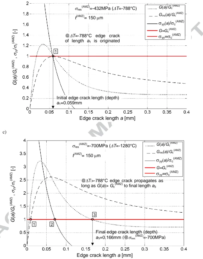
formation and propagation of an edge crack during cooling down from the reference temperature can be estimated. Figures 4a, 4b and 4c show the normalized incremental energy release rate
Ginc(a)/Gc (AMZ)
, the normalized energy release rate G(a)/Gc (AMZ)
and the normalized tensile stress
yy(a)/c(AMZ) for a given AMZ layer thickness, i.e. t(AMZ) = 150 µm, and compressive residual
stresses (in the AMZ layers) of ‒400 MPa, ‒432 MPa, and ‒700 MPa, respectively. These values correspond to T values of ‒730 °C, ‒788 °C and ‒1280 °C, respectively.
a) b) res (AMZ) =-400MPa (T=-730°C) t(AMZ)= 150 m
No edge crack is originated (nowhere yy≥c Ginc(a)≥Gc(AMZ))
Edge crack length a [mm]
G (a )/ Gc (A M Z ) , yy / c (A M Z ) [ -] G(a)/Gc(AMZ)
Ginc(a)/Gc(AMZ)
yy(a)/c(AMZ)
G=Gc (AMZ)
yy=c(AMZ)
c)
Figure 4. The normalized incremental energy release rate Ginc(a)/Gc(AMZ), energy release rate G(a)/Gc(AMZ) and tensile stress yy(a)/c(AMZ) for t(AMZ)=0.150mm and compressive residual stress
in AMZ layer: (a) res
(AMZ)=400MPa, (b) res (AMZ)=432MPa, (c) res (AMZ)=700MPa. res (AMZ) =-432MPa (T=-788°C)
Initial edge crack length (depth) a1=0.059mm
t(AMZ)= 150 m
@T=-788°C edge crack of length a1 is originated (by jump)
Edge crack length a [mm]
G (a )/ Gc (A M Z ) , yy / c (A M Z ) [ -] G(a)/Gc(AMZ)
Ginc(a)/Gc(AMZ)
yy(a)/c(AMZ)
G=Gc(AMZ)
yy=c(AMZ)
1
Final edge crack length (depth) a3=0.166mm (@res (AMZ) =-700MPa) res (AMZ) =-700MPa (T=-1280°C) t(AMZ)= 150 m
@T>-788°C edge crack propagates as long as G(a)> Gc(AMZ) to final length a3
Edge crack length a [mm]
G (a )/ Gc (A M Z ) , yy / c (A M Z ) [ -] G(a)/Gc (AMZ)
Ginc(a)/Gc(AMZ)
yy(a)/c(AMZ) G=Gc (AMZ) yy=c(AMZ) 1 2 3
If the difference between reference and investigated temperature is relatively low (e.g. T=‒730°C), the magnitude of compressive residual stresses remains moderate low (in this
particular case res(AMZ)=‒400MPa). As a result, no edge crack is initiated (see Figure 4a), because
either the energy or the stress criteria are not fulfilled at any point (i.e. Ginc(a)≤Gc (AMZ)
and yy<c).
In the particular situation that the specimen is cooled down with T=‒788°C, corresponding to a
value of residual stresses res(AMZ)=‒432MPa, both criteria are simultaneously fulfilled for the first
time (namely Ginc=Gc (AMZ)
and yy=c), and the edge crack is originated with a sudden jump from
zero length to length a1 = 59m, as is depicted in Figure 4b).
In the case that the specimen is reaching the room temperature, i.e. T=‒1280°C, the residual
compressive stress inside the AMZ layers reaches its maximum value of ‒700MPa. The corresponding stress and energy curves are illustrated in Figure 4c. According to the referred figure, once the crack is nucleated, it propagates through the AMZ layer provided that the ERR at the crack tip G(a) be larger than Gc
(AMZ)
. The final crack length after the cooling down process is thus determined by point 3 in Figure 4c, reaching a value of a3=166m in this case.
A consequence derived from these diagrams is that increments on T, associated with
increments of residual stress in the compressive layers, may yield the condition where the curve of
G(a) becomes higher than Gc (AMZ)
at all points along the possible edge crack path. In such a case, the edge crack would propagate through the entire AMZ layer, leading to the delamination of the laminate.
4.
Results and discussionThe influence of the AMZ layer thickness and magnitude of residual stress inside this layer on the formation and propagation of the edge crack is investigated using the FE model and applying the CC. Different laminate configurations are computed, where the thickness of the AMZ layer is varied in the interval 30 to 350m and the thicknesses of the ATZ layers correspondingly adjusted to reach a total thickness of 3mm. The magnitude of residual stress in the AMZ layers is considered between ‒200MPa and ‒800MPa for each laminate configuration. We caution the reader that, since the total height of the laminate is kept constant for this study, each configuration results in different volume ratios between ATZ and AMZ materials, and therefore different magnitude of residual stresses (upon the same T), see Appendix for more details. In order to enable a comparative study
of edge crack formation and propagation in laminates with different layer thicknesses at a given level of residual stress, a corresponding T (inducing that level of residual stress) has to be first
calculated for each laminate configuration.
After selecting a given residual stress level, a set of simulations is performed by introducing an edge crack with a length between 0m (no edge crack) and 400m (with a step of 1m), enabling
the estimation of G, Ginc and yy (along the prospective crack path) as a function of the edge crack
length a. These quantities are calculated through a FE analysis only for one specific temperature increment, i.e. T=100°C, and then (due to the linear elastic character of the solution) recalculated to arbitrary level of residual stress in the AMZ layer (for more information see the Appendix).
For illustrative purposes, we consider now the magnitude of residual stress in the AMZ layer to be res
(AMZ)
=‒200MPa. The normalized ERR and tangential stress yy ahead of the crack tip are
plotted together in Figure 5a. This plot clearly shows that no edge cracking is possible, because both the energy and stress conditions are not fulfilled for any potential edge crack length (i.e. the conditions yy≥c and Ginc(a)≥Gc
(AMZ)
are not simultaneously fulfilled for the range of edge crack length).
If the level of compressive stress is increased up to a value of res
(AMZ)=300MPa, as is shown in
Figure 5b, it can clearly be observed that, for AMZ layers equal or thicker than 222m, edge cracking is predicted, because both conditions yy≥c and Ginc(a)≥Gc(AMZ) are simultaneously
fulfilled (see Point 1 in Fig. 5b). The predicted initial length of the edge crack corresponds to ≈ 85µm. Once the edge crack is created, it propagates as long as the ERR at the crack tip remains higher than the fracture energy of the material, i.e. G(a) ≥Gc(AMZ). Again for layer thicknesses lower
than 222m, no edge cracking is predicted. On the other hand, when the AMZ layer is thicker or equal to ≈ 307µm, the edge crack propagates through the entire plane of the AMZ layer since
G(a)≥Gc (AMZ)
all along the crack path (G(a) is equal to Gc (AMZ)
only at the point 2 in Fig. 5b). Beyond that critical thickness, the edge crack would propagate through the entire AMZ layer, yielding total delamination of the laminate.
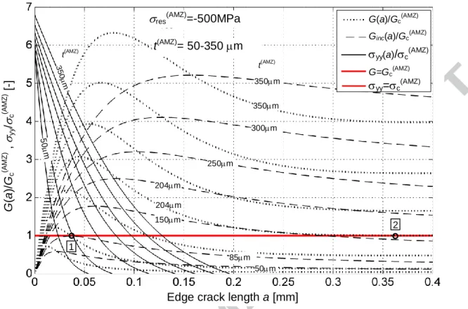
Further increasing the compressive stress level up to res(AMZ)=500MPa decreases the critical
thickness required for edge crack formation to 85m (see Fig. 5c). In addition, as a consequence of such high compressive stresses, another critical thickness results (i.e. 204 µm in Fig. 5c), where the
G(a) curve becomes higher than or equal to Gc(AMZ) at all points, along the possible edge crack path,
a)
b)
c)
Edge crack length a [mm]
G (a )/ Gc (A M Z ) , yy / c (A M Z ) [ -] G(a)/Gc(AMZ)
Ginc(a)/Gc(AMZ)
yy(a)/c(AMZ)
G=Gc(AMZ)
yy=c(AMZ)
t(AMZ)= 50-350 m
res(AMZ)=-200MPa
50 m 3 5 0 m t(AMZ) 50m 100m 150m 200m 250m 350m 300m t(AMZ) 350m t(AMZ) 350m 50m 222m t(AMZ)
Edge crack length a [mm]
G (a )/ Gc (A M Z ) , yy / c (A M Z ) [ -] G(a)/Gc(AMZ)
Ginc(a)/Gc(AMZ)
yy(a)/c(AMZ) G=Gc(AMZ) yy=c(AMZ) 100m 150m 200m 250m t(AMZ)= 50-350 m
res(AMZ)=-300MPa
50 m 1 350m 2 307m 307m 3 5 0 m 222m
Figure 5. Normalized incremental energy release rate Ginc(a)/Gc (AMZ)
, normalized energy release rate G(a)/Gc
(AMZ)
and normalized tensile stress yy(a)/c (AMZ)
, for different thicknesses of the compressive AMZ layer at the following residual compressive stress: (a) res(AMZ)=200MPa,
(b) res
(AMZ)=300MPa, and (c) res
(AMZ)=500MPa.
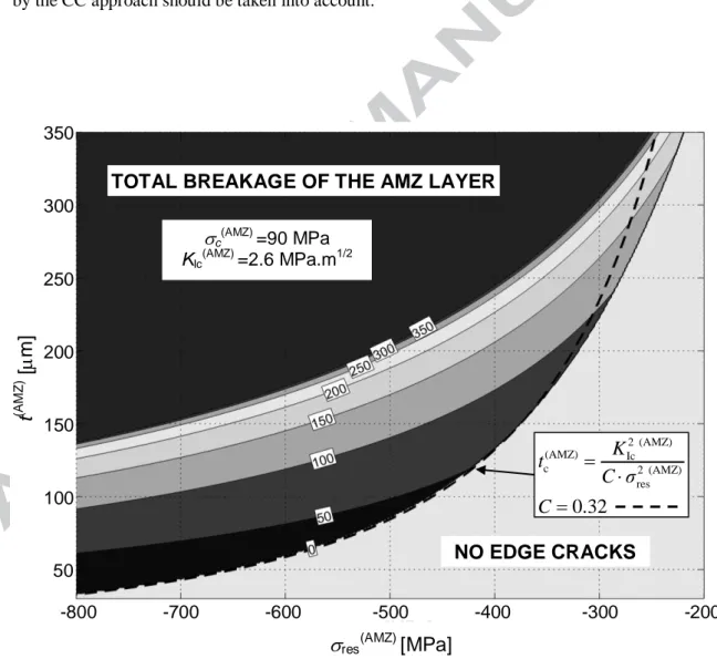
Figure 6 shows the combined effect of residual stress res (AMZ)
and AMZ layer thickness t(AMZ) on the final edge crack length, as is predicted by the parametric studies, where res(AMZ) is varied
between ‒200MPa and ‒800MPa and t(AMZ)
between 30µm and 350µm. The corresponding curves allow estimating the final edge crack depth (indicated in m in the curve) for corresponding values of res(AMZ) and t(AMZ). One can thus easily retrieve from this plot the critical combinations of both
parameters, which may lead to edge cracking. If their combination lays in the light grey area, i.e. at the bottom of the graph, no edge cracking is expected. If the pair (res(AMZ) and t(AMZ)) lays in the
central part of the graph, edge cracking is expected to occur and propagate into the AMZ layer a certain depth, as is prescribed by the number at the corresponding curve. Finally, the top dark grey area of the plot reveals the “undesired” combination of res
(AMZ)
and t(AMZ), which would lead to the total breakage of the AMZ layer (the energy release rate at the tip of the edge crack is higher than
Gc all along the prospective edge crack path – in the whole mid-plane of the AMZ layer).
The critical thickness of the AMZ layer leading to the edge cracking, i.e. tc (AMZ)
, can also be described using the equation derived (in a similar form) by Ho and Hillman in [35] and employed also in [38]:
Edge crack length a [mm]
G (a )/ Gc (A M Z ) , yy / c (A M Z ) [ -] G(a)/Gc(AMZ)
Ginc(a)/Gc(AMZ)
yy(a)/c(AMZ)
G=Gc(AMZ)
yy=c(AMZ) t(AMZ)= 50-350 m
res(AMZ)=-500MPa
50 m 3 5 0 m t(AMZ) 50m t(AMZ) 85m 204m 250m 300m 150m 350m 350m 1 2 204m
2 (AMZ) (AMZ) 2 (AMZ) res
,
Ic cK
t
C σ
(2)where KIc is the fracture toughness of the compressive layer, res is the in-plane compressive
residual stress, and C is a constant as estimated by the above authors to be equal to 0.34 (see [35] and [38] for more details). By implementing the CC approach to the solution of the edge cracking problem and fitting Eq. (2), we obtain a very similar result for C constant – namely C=0.32. For comparison purposes, the dependence of the critical layer thickness on the level of residual stress
res(AMZ), as is predicted by Eq. (2), is represented in Figure 6 by the black thick dotted line. One can
see a very good agreement of this relation with predictions made by the coupled stress-energy criterion, especially in the region of residual stresses 700MPa to 350MPa. Nevertheless, for residual stresses higher than 350MPa, Eq. (2) may no longer be valid, and thus predictions made by the CC approach should be taken into account.
Figure 6. Depths of the edge cracks in m against residual compressive stress in the AMZ layer and thickness of the compressive layer. The numbers in white boxes inside the plot denote the final edge crack depth in m for certain combination of res
(AMZ) and t(AMZ). 2 (AMZ) (AMZ) Ic c 2 (AMZ) res
0.32
K
t
C σ
C
c(AMZ) =90 MPa KIc(AMZ) =2.6 MPa.m1/2TOTAL BREAKAGE OF THE AMZ LAYER
NO EDGE CRACKS
-800 -700 -600 -500 -400 -300 -200 350 300 250 200 150 100 50
res(AMZ)[MPa]
t
(AM Z )[
m]
5.
ConclusionsThis work presents a novel approach to predict the onset and propagation of surface cracks (namely edge cracks) in ceramic laminates, associated with the residual stresses developed after cooling down from the sintering step. A full parametric 2D finite element model has been developed to simulate the initiation and propagation of the edge crack in the compressive layers. The conditions for crack initiation/propagation are assessed using a stress-energy coupled criterion. The analysis only requires the values of the elastic modulus and Poisson’s ratio of the layers, the coefficient of thermal expansion, and the toughness and tensile strength of the compressive layer. There is no adjustable parameter, and there is no need to assume the presence of surface defects to initiate fracture. It is further found that, for a given thickness of the compressive layer, no edge crack is to initiate for relatively low internal (in-plane) compressive residual stress in the layer. For higher stress values, edge crack may initiate and grow in a stable manner. Finally, for relatively higher stress values, the formation of edge cracks is followed by the fracture (delamination) of the entire layer in an unstable fashion. Additional work is needed to validate the obtained results on different real specimens with various thicknesses and levels of residual stresses, aiming to provide guidelines for the fabrication of layered ceramics with controlled surface cracks.
Acknowledgements
The work has been supported by the NETME Centre established thanks to a financial support of the European Regional Development Fund under the Operational Program Research and Development for Innovation. The presented results have been obtained within NETME CENTRE PLUS (LO1202) project co-funded by the Czech Ministry of Education, Youth and Sports within the support program National Sustainability Program I.
A financial support of the Czech Science foundation under the project no. 14-11234S is also gratefully acknowledged.
References
[1] Griffith AA. The Phenomena of Rupture and Flow in Solids Philosophical Transactions of the Royal Society A: Mathematical, Physical and Engineering Sciences 1921;221:163-98.
[2] Kingery WD, Bowen HK, Uhlmann DR. Introduction to ceramics. New York: John Wiley & Sons, 1976.
[3] Danzer R. A general strength distribution function for brittle materials. Journal of the European Ceramic Society 1992;10:461-72.
[4] Morrell R. Fractography of Brittle Materials. In: Anonymous , Teddigton: National Physical Laboratory; 1999, p. 86.
[5] Danzer R. Mechanical Failure of Advanced Ceramics: The Value of Fractography Key Eng Mat 2002;223:1-18.
[6] Lawn B. Fracture of brittle solids. 2nd ed. New York: Cambridge University Press, 1993. [7] Munz D, Fett T. Ceramics. Mechanical Properties, Failure Behaviour, Materials Selection.
Berlin: Springer, 1999.
[8] Danzer R, Lube T, Supancic P, Damani R. Fracture of advanced ceramics. Advanced Engineering Materials 2008;10:275-98.
[9] Lange FF. Powder processing science and technology for increasing reliability. J. Am. Ceram. Soc. 1989;72:3-15.
[10] Green DJ, Tandon R, Sglavo VM. Crack arrest and multiple cracking in glass through the use of designed residual stress profiles. Science 1999;283:1295-7.
[11] Qi YE, Zhang YS, Fang Y, Hu LT. Design and preparation of high-performance alumina functional graded self-lubricated ceramic composites. Composites Part B: Engineering 2013;47:145-9.
[12] Clegg WJ, Kendall K, Alford NM, Button TW, Birchall JD. A Simple Way to Make Tough Ceramics. Nature 1990;347:455-7.
[13] Marshall DB, Ratto JJ, Lange F. Enhanced fracture toughness in layered microcomposites of Ce-ZrO2 and Al2O3. J. Am. Ceram. Soc. 1991;74:2979-87.
[14] Chartier T, Merle D, Besson JL. Laminar ceramic composites. Journal of the European Ceramic Society 1995;15:101-7.
[15] Cutler WA, Zok FW, Lange FF. Mechanical Behavior of Several Hybrid Ceramic-Matrix-Composite Laminates. Journal of the American Ceramic Society 1996;79:1825-33.
[16] Clegg WJ. Design of Ceramic Laminates for Strucutral Applications. Materials Science and Technology 1998;14:486-95.
[17] Rao M, Sanchez-Herencia J, Beltz G, McMeeking RM, Lange F. Laminar ceramics that exhibit a threshold strength. Science 1999;286:102-5.
[18] McMeeking RM, Hbaieb K. Optimal Threshold strength of laminar ceramics. Zeitschrift metallkunde 1999;90:1031-6.
[19] Moon RJ, Hoffmann M, Hilden J, Bowman K, Trumble K, Rödel J. R-Curve Behavior in Alumina-Zirconia Composites with Repeating Graded Layers. Engineering Fracture Mechanics 2002;69:1647-65.
[20] Orlovskaya N, Lugovy M, Subbotin V, Radchenko O, Adams J, Chheda M et al. Robust design and manufacturing of ceramic laminates with controlled thermal residual stresses for enhanced toughness. 2005;40:5483-5490.
[21] Sglavo VM, Paternoster M, Bertoldi M. Tailored Residual Stresses in High Reliability Alumina-Mullite Ceramic Laminates. Journal of the American Ceramic Society 2005;88:2826-32.
[22] Bueno S, Baudín C. Layered materials with high strength and flaw tolerance based on alumina and aluminium titanate. J. Eur. Ceram. Soc. 2007;27:1455-62.
[23] Bermejo R, Torres Y, Baudin C, Sánchez-Herencia AJ, Pascual J, Anglada M et al. Threshold strength evaluation on an Al2O3–ZrO2 multilayered system. J Eur Ceram Soc 2007;27:1443-8.
[24] Tomaszewski H, Weglarz H, Wajler A, Boniecki M, Kalinski D. Multilayer ceramic composites with high failure resistance. Journal of the European Ceramic Society 2007;27:1373-7.
[25] Bermejo R, Pascual J, Lube T, Danzer R. Optimal strength and toughness of Al2O3–ZrO2 laminates designed with external or internal compressive layers. Journal of the European Ceramic Society 2008;28:1575-83.
[26] Bermejo R, Baudín C, Moreno R, Llanes L, Sánchez-Herencia AJ. Processing optimisation and fracture behaviour of layered ceramic composites with highly compressive layers. Composites Sci Technol 2007;67:1930-8.
[27] Bermejo R, Torres Y, Sánchez-Herencia AJ, Baudín C, Anglada M, Llanes L. Residual stresses, strength and toughness of laminates with different layer thickness ratios. Acta Materialia 2006;54:4745-57.
[28] Lugovy M, Slyunyayev V, Subbotin V, Orlovskaya N, Kübler J. Crack Arrest in Si3N4-Based
Layered Composites with Residual Stress. Composites Science and Technology 2004;64:1947-57.
[29] Lugovy M, Slyunyayev V, Orlovskaya N, Blugan G, Kübler J, Lewis MH. Apparent Fracture Toughness of Si3N4-Based Laminates with Residual Compressive or Tensile Stress in Surface
Layers. Acta Materialia 2005;53:289-96.
[30] Sglavo VM, Bertoldi M. Design and Production of Ceramic Laminates with High Mechanical Reliability. Composites Part B 2006;37:481-9.
[31] Bermejo R, Torres Y, Anglada M, Llanes L. Fatigue behavior of alumina-zirconia multilayered ceramics. Journal of the american ceramic society 2008;91:1618-25.
[32] Lube T. Mechanical Properties of Ceramic Laminates Key Eng Mat 2007;333:87-96.
[33] Ho S, Suo Z. Tunneling cracks in constrained layers. Journal of Applied Mechanics 1993;60:890-4.
[34] Hillman C, Suo Z, Lange F. Cracking of Laminates Subjected to Biaxial Tensile Stresses. Journal of the American Ceramic Society 1996;79:2127-33.
[35] Ho S, Hillman C, Lange FF, Suo Z. Surface Cracking in Layers Under Biaxial, Residual Compressive Stress J Am Ceram Soc 1995;78:2353-9.
[36] Bermejo R, Sanchez-Herencia AJ, Baudin C, Llanes L. Residual stresses in Al2O3-ZrO2 multilayered ceramics: nature, evaluation and influence on the structural integrity. Boletin De La Sociedad Espanola De Ceramica Y Vidrio 2006;45:352-7.
[37] Hbaieb K, McMeeking R, Lange F. Crack bifurcation in laminar ceramics having large compressive stress. International Journal of Solids and Structures 2007;44:3328-43.
[38] Chen CR, Bermejo R, Kolednik O. Numerical analysis on special cracking phenomena of residual compressive inter-layers in ceramic laminates. Engineering Fracture Mechanics 2010;77:2567-76.
[39] Leguillon D, Sevecek O, Martin É, Bermejo R. Edge cracking due to a compressive residual stress in ceramic laminates. Comp Rend Mec 2015;343:192-8.
[40] Leguillon D. Strength or toughness? A criterion for crack onset at a notch. European Journal of Mechanics, A/Solids 2002;21:61-72.
[41] Martin E, Leguillon D. Energetic conditions for interfacial failure in the vicinity of a matrix crack in brittle matrix composites. Int J Solids Structures 2004;41:6937-48.
[42] Chlup Z, Hadraba H, Drdlik D, Maca K, Dlouhy I, Bermejo R. On the determination of the stress-free temperature for alumina–zirconia multilayer structures. Ceram Int 2014;40:5787-93.
[43] Oël HJ, Fréchette VD. Stress Distribution in Multiphase Systems: I, Composites with Planar Interfaces J Am Ceram Soc 1967;50:542-9.
[44] Green DJ, Cai PZ, Messing GL. Residual stresses in alumina–zirconia laminates Journal of the European Ceramic Society 1999;19:2511-7.
[45] Cai PZ, Green DJ, Messing GL. Constrained Densification of Alumina/Zirconia Hybrid Laminates, I: Experimental Observations of Processing Defects J Am Ceram Soc 2005;80:1929-39.
[46] Cai PZ, Green DJ, Messing GL. Constrained Densification of Alumina/Zirconia Hybrid Laminates, II: Viscoelastic Stress Computation J Am Ceram Soc 2005;80:1940-8.
[47] Sestakova L, Bermejo R, Chlup Z, Danzer R. Strategies for fracture toughness, strength and reliability optimisation of ceramic-ceramic laminates. IJMR 2011;102:613-26.
Appendix
In every case where dissimilar materials are sealed together through a relative strong interface and subsequently undergo differential dimensional change, stresses arise between the materials [43]. Hence, a particular challenge in the processing of ceramic laminates is to understand the nature of these residual stresses, especially if they have to be used to enhance their mechanical properties. In ceramic laminates, residual stresses can be due to different factors: (i) different CTEs, (ii) phase transformations and/or (iii) chemical reactions. For ideal elastic materials, neglecting the influence of the external surfaces (where stresses may relax) and considering the laminate as an infinite plane plate (i.e. zero net bending moment), the stress field can be determined analytically [14,43,44]. In each layer, a homogeneous and biaxial residual stress state exists far from the free edges. The stress magnitude in each layer,
res,i, can be defined as follows:i i i i i i i
E
T
E
1
)
(
1
, res (A.1)where
E
i,
i and
i are material properties of the ith layer (i.e. Young’s modulus, Poisson’s ratio and coefficient of thermal expansion, respectively).
i (
i)T is the mismatch strain of the ith layer, where the coefficient
is given as a weighted averaged expansion coefficient of the laminate: 1 1 11 N N i i i i i i i i i E t
E t
(A.2)with
t
i being the thickness of the ith
layer and N the number of layers. Note that the reference temperature Tref is, in practice, not easy to determine. For typical alumina-based or silicon-based
ceramics, this stress-free empirical temperature is generally between 1200 °C and the sintering temperature (approx. 1500 °C), depending on the components, compositions, etc. [42,45,46].
A particular simple laminate case is that using only two types of layer materials (A and B). In such a case, Eq. (A.2) can be written in the form [30]:
A B A B A A B B A B A, B, A, B, 1 1 1 1 A B A B
1
1
1
1
n n n n i i i i i i i iE
E
E
E
t
t
t
t
(A.3)According to Eq. (11), the magnitude of the residual stresses depends on the ratio between the total thickness of the layers of type A (i.e. TA
tA,i) and B (i.e. TB
tB,i). The ratio of total thickness of the layer materials equals their volume ratio:T
B/
T
A
V
B/
V
A. Thus the magnitude ofresidual stresses depends only on this volume ratio and not on the thickness of the individual layers
i [47]:
A B res, A, B, B A B A 1 1 n n i i j j i i j jf
t
t
f T T
f V V
(A.4)In order to study the influence of the AMZ layer thickness and magnitude of residual stress inside this layer on the formation and propagation of the edge crack, different laminate configurations have been calculated, where the thickness of the AMZ layer has been varied in the interval (30-350m) and the thicknesses of the ATZ layers correspondingly tailored to reach a total thickness of 3mm. Since the total thickness of the laminate is kept constant, the change of the AMZ layer thickness modifies the volume ratio between materials, and thus the magnitude of residual stress in the AMZ layers, as is inferred from Eq. (A.3).
Note:
The solved problem is considered as linear elastic. Therefore, solution of just one arbitrary residual stress state (given by arbitrary T) in a laminate of specific volume ratio (AMZ layer thickness) is
sufficient. One can afterwards recalculate the results of yy, G(a), and Ginc(a) along the crack path,
to values corresponding to arbitrary residual stress state
'
res(AMZ) lying in the investigated interval 800 MPa to 200 MPa. The multiplication factor for this conversion: (i) in the case of stress recalculation, it is equal to the ratio of residual stress in the AMZ layer for given T (calculated forinstance by Eq. (A.1) or using FEM) to the desired level of residual stress in the above mentioned investigated interval; (ii) in the case of energy release rate recalculations, it is the factor from (i) considered in the second power as follows:
(AMZ) res (AMZ) res 2 (AMZ) res (AMZ) res 2 (AMZ) res inc inc (AMZ)
res
'
' ( )
( )
'
'( )
( )
'
' ( )
( )
.
yya
yya
G a
G a
G
a
G
a
(A.5) (AMZ) res'
is the desired level of residual stress in the AMZ layer and
res(AMZ) is the level of compressive residual stress reached in the laminate of given volume ratio subjected to a specific T(in our case T=100). The quantities yy, G(a), and Ginc(a) on the right-hand side of Eqs. (A.5)
the left-hand side of Eqs. (A.5) correspond to values which would be calculated in the same way in a laminate with the level of residual stress
![Figure 1. Schematic of surface cracks in ceramic laminates designed with tensile (t) and compressive (c) residual stresses [32]](https://thumb-eu.123doks.com/thumbv2/123doknet/13134566.388249/5.892.260.687.359.654/figure-schematic-surface-laminates-designed-compressive-residual-stresses.webp)
![Table 1. Material properties of the layers of the ceramic laminate [17]](https://thumb-eu.123doks.com/thumbv2/123doknet/13134566.388249/6.892.98.722.546.975/table-material-properties-layers-ceramic-laminate.webp)