Design and Characterization of a Liquid-Fueled Microcombustor
The MIT Faculty has made this article openly available.
Please share
how this access benefits you. Your story matters.
Citation
Peck, Jay et al. “Design and Characterization of a Liquid-Fueled
Microcombustor.” Journal of Engineering for Gas Turbines and
Power 133, 7 (2011): 072301 © 2011 American Society of Mechanical
Engineers
As Published
http://dx.doi.org/10.1115/1.4002621
Publisher
American Society of Mechanical Engineers (ASME)
Version
Final published version
Citable link
http://hdl.handle.net/1721.1/114785
Terms of Use
Article is made available in accordance with the publisher's
policy and may be subject to US copyright law. Please refer to the
publisher's site for terms of use.
Jay Peck
1 e-mail: [email protected]Stuart A. Jacobson
2Ian A. Waitz
Department of Aeronautics and Astronautics, Gas Turbine Laboratory, Massachusetts Institute of Technology, Cambridge, MA 02139Design and Characterization of a
Liquid-Fueled Microcombustor
As part of an effort to develop a microscale gas turbine engine, this paper presents the design and experimental characterization of a microcombustor that catalytically burns JP8 fuel. Due to the high energy densities of hydrocarbon fuels, microscale heat engines based on them may enable compact power sources with specific energies higher than those of current battery systems. In addition, utilizing a commonly available logistics fuel would provide advantages for military applications. Thus, a microscale engine burning JP8 fuel is attractive as a portable power source. A liquid-fueled microcombustor with a combustion chamber volume of 1.4 cm3 and an overall die size of 36.4⫻36.4
⫻6.5 mm3was designed, microfabricated, and experimentally characterized. Two
con-figurations were tested and compared, one with the combustion chamber entirely filled with a catalyst and the other with the combustion chamber partially filled with a catalyst. In the configuration filled with a catalyst, JP8 combustion was sustained at mass flow rates up to 0.1 g/s and an exit gas temperature of 780 K; an overall combustor efficiency of 19% and a power density of 43 MW/m3were achieved. The primary limitation on
increasing the mass flow rates and temperature further was the structural failure of the device due to thermal stresses. With the partially filled configuration, a mass flow rate of 0.2 g/s and a corresponding power density of 54 MW/m3were obtained. The exit gas
temperature for the partially filled configuration was as high as 720 K, and the maximum overall efficiency was over 22%. Although the reduced amount of catalyst led to incom-plete combustion, smaller thermal losses resulted in an increase in the overall combustor efficiency and power density. A nondimensional operating map was constructed based on the experiment, and it suggests that improving the thermal efficiency would be necessary to achieve higher efficiencies in the device. 关DOI: 10.1115/1.4002621兴
1 Introduction
There have been extensive efforts to develop a portable electric power source that can improve upon the performance of current battery technology. Because hydrocarbons have a specific energy of approximately 40 MJ/kg, whereas the best lithium-ion batteries have about 0.5 MJ/kg, a hydrocarbon-based device with a chemical-to-electric efficiency of only a few percent could have benefits over batteries关1兴. Fuel-burning devices can also be re-filled quickly, and one can easily and accurately check their cur-rent level of fill. Both solid-state heat-to-electricity converters 关2,3兴 and internal combustion engines 关4–6兴 are being studied for the micropower generation using combustion. Epstein et al.关7,8兴 led an initiative to design and build a shirtbutton-sized gas turbine engine using silicon semiconductor microfabrication technology. This engine is about one-hundredth the length scale of its conven-tional counterparts, thus one-millionth the volume, and is referred to as a microengine关9兴. Bench-top microengines are designed to produce about 10 W of electrical power or 0.1 N of thrust within a package about 1 cm3in volume. The resulting power density would be on the order of 10 MW/m3. Like their larger counter-parts, the microengine requires a high temperature combustion system to convert chemical energy stored in fuel into fluid thermal and kinetic energy.
Previous research at MIT made progress on the development of microcombustor technology for this application. Waitz et al.关10兴 were the first to study combustion systems for microengines. In a
flame tube experiment, they showed that a lean-burning hydrogen-air combustor was a feasible initial developmental strategy for microcombustors. Mehra et al.关11,12兴 and Spadaccini et al. 关13兴 built hydrogen microcombustors mimicking the microengine’s flow geometries and thermal boundary conditions. They did not include the rotating spool, which is complex to fabricate and not considered critical to the microcombustor functionality. In the hy-drogen devices, exit gas temperatures in excess of 1600 K, effi-ciencies over 85%, and a power density of 1400 MW/m3were achieved.
Hydrocarbon fuels such as ethene and propane were also tested in these devices, but the mass flow rate capabilities were signifi-cantly limited since the reaction time-scales of hydrocarbon fuels are approximately an order of magnitude longer than those of hydrogen. To broaden the operating range of the microcombustor, Spadaccini et al.关14,15兴 developed a catalytic microcombustor. A platinum-coated, high porosity metal foam was placed inside the combustion chamber. The enhanced reaction kinetics of catalytic combustion increased the mass flow rate capabilities of the de-vice; stable propane-air combustion was achieved at mass flow rates in excess of 0.35 g/s. However, exit gas temperatures were somewhat low and limited to 1100 K, owing to lower thermal efficiencies. Nevertheless, the increased mass flow rate resulted in a combustor power density of 1200 MW/m3 burning propane fuel, which is an 8.5-fold increase over the noncatalytic propane-air combustion. Despite the progress on hydrogen and propane microcombustors, the microengine would be more practical if it utilized a fuel that is easier to store and transport, such as JP8. Development of a reliable liquid-fueled combustion system suit-able for integration with the microengine is the subject of this paper.
2 Liquid-Fueled Microcombustor Challenges
Key design requirements for the microengine combustor in-clude significant temperature rise, high efficiency, low pressure
1
Present address: Aerodyne Research Inc., 45 Manning Road, Billerica, MA 01821.
2
Present address: Joule Biotechnologies, Inc., 83 Rogers Street, Cambridge, MA 02142.
Contributed by the International Gas Turbine Institute共IGTI兲 of ASME for pub-lication in the JOURNAL OFENGINEERING FORGASTURBINES ANDPOWER. Manuscript received April 20, 2010; final manuscript received April 26, 2010; published online March 16, 2011. Editor: Dilip R. Ballal.
Journal of Engineering for Gas Turbines and Power JULY 2011, Vol. 133 / 072301-1
drop, structural integrity, reliable ignition, and flame stability. Be-cause the high power density of a gas turbine engine is realized by passing large mass flow rates through small cross-sectional areas, flow residence times in the combustor are inevitably short and may become similar or even less than the chemical reaction times that are invariant with size. This can lead to incomplete combus-tion, low efficiencies, and sometimes blowout of the flame. More-over, due to enhanced heat transfer at microscale共smaller length scales result in higher surface area-to-volume ratios兲, the micro-combustor tends to lose a relatively large fraction of the flow enthalpy across the combustor walls. Thin walls and high thermal conductivity of silicon make the structure nearly isothermal, lead-ing to poor thermal isolation of the combustor and exacerbatlead-ing the heat loss problem. Nonadiabatic operation lowers combustor temperatures and the low temperatures reduce chemical reaction rates, making the residence time issue more severe. Thus, fluid dynamics, chemical kinetics, and heat transfer are strongly coupled in a microscale combustor.
Using a liquid fuel poses additional challenges. It is known that the gas-phase reaction time is not significantly different for light and heavy hydrocarbons. Levebvre et al.关16兴 published an experi-mental report on ignition delays of various fuels, indicating that the spontaneous ignition delays of premixed propane and prevaporized/premixed JetA共a kerosene-based jet fuel similar to JP8兲 are similar. Although the detailed chemistry of catalytic JP8 combustion is more complex than that for propane, we may as-sume that there will not be a significant difference in the catalytic reaction time-scales between propane and JP8. However, the dif-fusion time-scale, which is approximately ten times longer than the reaction time-scale in the microcombustor environment, is longer for JP8 fuel than for propane due to heavier molecules. The mixing time, which is usually longer than the diffusion time and the reaction time,3is also longer for heavy hydrocarbon fuels.
Considering these aspects, a logical strategy for making the liquid-fueled microcombustor as small as possible is to prevapor-ize and premix the fuel and air before entering the combustion chamber. To further reduce the combustion time-scale, catalytic combustion is also considered necessary.
3 Design and Fabrication
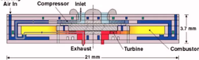
In order for the microcombustor to be compatible for integra-tion with the microengine, it must have a geometry and a flow path that are similar to the microengine. Hence, the combustion chamber is in the shape of an annulus, allowing the flow to enter from the outer diameter, travel radially toward the inner diameter, and finally exit through the inner diameter. A schematic of the microengine flow path is shown in Fig. 1. Operating parameters were also picked to be consistent with those of the microengine. Table 1 specifies the design operating conditions for the liquid-fueled microcombustor.
A reduced-order design model was developed to estimate the time-scale of catalytic JP8 combustion. The model is valid for a slow-diffusing fuel, with its diffusion time-scale much longer than
the reaction time-scale. Under this condition, the overall combus-tion time can be approximated as the diffusion time of fuel mol-ecules. This approximation also eliminates the need for a surface kinetics model, which is not available for JP8 combustion. In this model, the combustor is assumed to be a simple circular tube, containing an internal flow that is steady, adiabatic, compressible 共variable density兲, and viscous. The inner wall of the tube is treated as catalytic, with chemical reactions occurring only on the walls, and no gas-phase combustion. The combustion process is considered to be constant pressure. The fuel is prevaporized and premixed with air before entering the combustion chamber. With these assumptions, the reacting flow problem becomes a mass transfer problem. The fuel concentration profile is zero at the wall and peaks at the center of the tube. This concentration gradient causes the fuel molecules to diffuse to the catalytic walls. Because the reaction rates are much faster than the diffusion rates, the fuel molecules are immediately consumed by chemical reactions. Us-ing a mass transfer equation, the model computes the amount of fuel that diffuses to the wall and is subsequently oxidized. This fuel consumption can be traced along the tube, and a lengthwise profile of the fuel concentration can be obtained. Then, the axial location where the fuel concentration becomes 10% of the initial concentration can be found, and the time for the flow to reach this location can be considered as the overall time-scale of JP8 com-bustion. To calculate diffusion rates, JP8 fuel was approximated as C13H23.4with average molar weight of about 179关18兴. In the bulk stream, the fluid density and the specific heat were represented by those of air since the stoichiometric mixture has only 7% fuel by weight. Then, the mass transfer equation can be written as
d共TCb兲
dt = −
ShDDab
R2 共TCb兲 共1兲
where T is the fluid temperature, Cbis the cross-section-averaged concentration of fuel molecules, and R is the radius of the reaction tube. The Sherwood number ShDis analogous to the Nusselt num-ber in heat transfer, and the molecular diffusion coefficient Dab can be given by the Fuller correlation关19兴 for the corresponding temperature and pressure:
Dab= 1.013⫻ 10−2T1.75 P
冑1
/Ma+ 1/Mb 共va1/3+vb1/3兲2 共2兲 where T is the temperature in K, P is the pressure in Pa, MaandMbare the molar weights of the species a and b, andvaandvbare the diffusion volumes of the species a and b.
Conservation of energy provides a relationship between tem-perature and concentration:
dT dt = − hf/ CpT + dCp dT T 2 d共TCb兲 dt 共3兲
where hfis the heating value of JP8, is the fluid density, and Cp is the constant pressure specific heat.4
3
According to Dodds and Bahr关17兴, of the typical 5–8 ms combustor residence time in a conventional gas turbine combustor, approximately 60%共3–5 ms兲 is de-voted to fuel vaporization and mixing and about 40%共2–3 ms兲 to mixing of dilution air. The chemical reaction time is fairly negligible.
4Values of C
pwere evaluated as if the working fluid is pure air, which is in fact
not the case. This assumption generally underpredicts Cpby about 15% compared
with the more rigorously estimated Cpof the combustion reactants and products.
Fig. 1 Cross-sectional view of the MIT microengine
Table 1 Operational specifications of the liquid-fueled
microcombustor
Parameter Value
Total mass flow rate 0.3 g/s
Fuel flow rate 0.04 g/s
Combustor exit temperature 1300 K
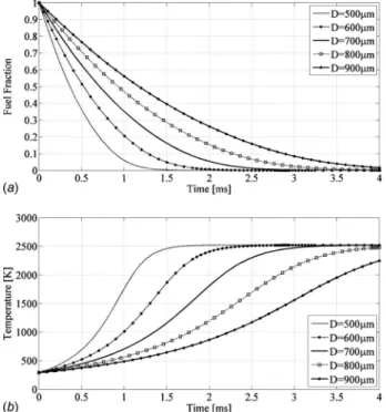
Solving this set of coupled nonlinear differential equations nu-merically with appropriate initial conditions and fluid properties, it was found that the fuel concentration falls below 10% of the initial concentration in approximately 2.5 ms. Figure 2 shows a typical model result. The characteristic diameter of our catalyst is less than 700 m, so the figure indicates that 2.5 ms residence time should be sufficient. Based on this result, the combustion chamber was sized to be 1.4 cm3to ensure that the flow residence time is longer than 2.5 ms at a design flow rate of 0.3 g/s and a pressure of 2 atm.
In conventional gas turbine engines, fuel is usually injected directly into the combustion chamber in the form of droplets. For microcombustor applications, however, the fuel needs to be vapor-ized and mixed with air before entering the combustion chamber due to the short flow residence times available. Considering that the microengine has readily available hot surfaces, typically at a temperature higher than the final boiling point of JP8, a fuel va-porizer with 49 microchannels共hydraulic diameter ⬇0.5 mm and length⬇10 mm兲 was designed. More details of the design
pro-cess can be found in Ref. 关20兴. This design benefits the overall engine cycle by recuperating heat lost to the structure while va-porizing the fuel.
Figure 3 shows exploded views of the liquid-fueled microcom-bustor. The test rig consists of six layers that are either bonded or mechanically clamped. As described in the figure, air and fuel are supplied through the holes near the edge in layer 2, go down along the channels in layer 1, and enter the device through the holes on the opposite end of layer 2. The air goes directly into the mixing chamber, and the fuel enters the vaporizer at the outer diameter. The fuel is vaporized in the microchannels and injected into the mixing chamber through a set of 100 m injection holes. The fuel and air mix while flowing radially outward and enter the combustion chamber through the inlet slots. The fuel-air mixture is catalytically combusted in the combustion chamber while flow-ing radially inward. Finally, the combustion product exits the de-vice through the exit nozzle. All the layers are held together by spring-loaded clamps made of machinable glass ceramics. Table 2 lists key dimensions of the test rig.
The liquid-fueled microcombustor rig is a hybrid structure con-sisting of three different materials: silicon, sapphire, and SD-2 glass. The sapphire combustion chamber共layer 5兲, exit tube, and SD-2 packaging glass 共layer 2兲 were fabricated with ultrasonic machining by Bullen, Inc.共Easton, OH兲. The three silicon layers were microfabricated in the Micro Technology Laboratory共MTL兲 at MIT. The catalytic insert was fabricated from nickel foam共with approximately 90% porosity兲 that was cut into the shape of the combustion chamber in the MIT machine shop and coated with platinum in MIT’s Technology Laboratory for Advanced Materials and Structures共TELAMS兲 by dipping it in platinic acid. Silicon
Fig. 2 Typical result of the catalytic combustion model for
various tube diameters„= 1.0 and P = 2.0 atm…
Fig. 3 Final design of the liquid-fueled microcombustor test rig
Table 2 Key dimensions of the test rig
Group Parameter Value
Overall Overall die size 36.4⫻36.4⫻6.5 mm3
Packaging block共layer 2兲 36.4⫻70.0 mm2
Combustion chamber Outer radius 16.7 mm
Inner radius 6.5 mm
Height 2 mm
Vaporizer Number of channels 49
Length of each channel 10 mm Inlet hydraulic diameter 595 m Outlet hydraulic diameter 320 m Fuel injection holes Number of holes 50
Diameter of each hole 100 m
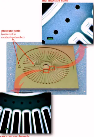
microfabrication mainly involved photolithography with seven photomasks and deep reactive ion etching共DRIE兲 using an induc-tively coupled plasma共ICP兲 etcher 共Surface Technology Systems, Inc., Redwood City, CA兲. Silicon fusion bonding and silicon-to-glass anodic bonding were also used. Figure 4 shows images of the microfabricated vaporizer channels and the fuel injection holes.
4 Experimental Characterization: Filled Catalyst
Configuration
Catalytic combustion of JP8 was successfully stabilized in the device, and experimental data were collected under various equivalence ratios and mass flow rates. First, a configuration with the combustion chamber entirely filled with a catalyst was tested, and results are presented in this section.
To ignite catalytic combustion, the catalyst must first be acti-vated关19兴. It is known that platinum becomes activated for hy-drocarbon combustion when it is heated to temperatures above 600 K. To achieve this level of preheating, hydrogen was burned in the device prior to switching to JP8. Using this procedure, catalytic JP8 combustion was sustained successfully in the micro-combustor test rig, as is evidenced by the glowing catalytic insert shown in Fig. 5.
4.1 Temperature Response. The temperature response of
catalytic JP8 combustion is plotted versus the total 共air+fuel兲 mass flow rate in Figs. 6 and 7. Temperature measurements are obtained by using 250 m unsheathed type K thermocouples. The exit gas temperature is measured at the exit nozzle, and the structural temperatures are measured around both the outer rim and the exit of the combustion chamber. The two structural tem-perature measurements differed by less than 10 K, which is within
the 95% confidence uncertainty range. As included in each figure, 95% confidence uncertainties for the exit gas temperature mea-surements are⫾32 K and ⫾12 K for the structural temperature.
Figure 6 shows the exit gas temperature as a function of the equivalence ratio for each mass flow rate setting. Although mea-sured data lie within the uncertainty bands of one another, a higher mass flow rate generally resulted in a higher temperature at the same equivalence ratio. Catalytic JP8 combustion was stabilized at equivalence ratios as low as 0.7 and as high as 1.4. Whereas there is normally a peak around the equivalence ratio of 1.0 for gas-phase combustion, no peak was observed in this experiment. This is because fuel conversion efficiency is low, and the combus-tion is limited by the diffusion of the fuel. The higher the concen-tration of fuel molecules, the higher the diffusion rate becomes, and more fuel can be burned, producing higher temperature.
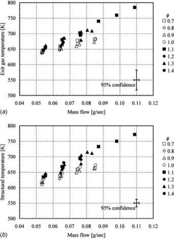
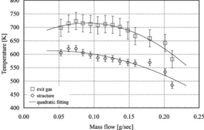
Figure 7 shows the exit gas temperature and the structural perature as functions of the mass flow rate. The structural tem-perature plotted is an average between the two structural tempera-ture measurements. Stable combustion was shown at a mass flow rate as high as 0.1 g/s 共Fig. 7兲, and the corresponding exit gas temperature was 780 K共=1.1兲. In general, the temperatures in-crease with the mass flow rate, which indicates that the perfor-mance of the combustor is not limited by chemical efficiencies in this range, showing a potential to allow a higher mass flow rate. However, the design mass flow rate of 0.3 g/s was not achieved because of a structure failure, due to excessive thermal stresses in the sapphire. There is little difference between the exit gas tem-peratures and the structural temtem-peratures, as is typical for catalytic combustion关19兴. This is because the chemical reactions occur on the catalytic surfaces, and the heat is transferred to the bulk gas
Fig. 4 Front side of the completed silicon piece„showing the
front side of layer 3…
Fig. 5 Photograph of the JP8 combustor in operation
Fig. 6 JP8 combustion result: exit gas temperature versus
via convection 共heat transfer by radiation becomes significant when the catalyst temperature exceeds 800 K兲. Due to the exis-tence of short conduction paths with relatively small thermal re-sistance between the catalytic insert and the sapphire structure, the heat tends to readily flow from the catalyst to the structure, result-ing in high structural temperatures.
Based on the temperature data, the power density can be calcu-lated as
power density = fluid power combustor volume=
共m˙a+ m˙f兲hexit− m˙ahinlet
V
共4兲 In this device, the maximum power density achieved was some-what low at 43 MW/m3.
4.2 Efficiency Breakdown. From the experimental
measure-ments, the overall combustor efficiency can be calculated by di-viding the enthalpy gain of the fluid by the maximum possible fuel power that may be released关21兴.
overall=
共m˙a+ m˙f兲hexit− m˙ahinlet
m˙fhf
共5兲 where m˙aand m˙fare the mass flow rates of air and fuel, respec-tively, hinletand hexitare the specific enthalpies at the inlet and the exit, and hfis the lower heating value of JP8. Using the structural temperature data and a 1D heat transfer model, it can be estimated how much heat is lost through the device. Adding the heat loss to the enthalpy gain of the fluid gives the total amount of heat that has been released from the fuel. Dividing the total heat release by the maximum fuel power that could have been released yields chemical efficiency:
chemical=
关共m˙a+ m˙f兲hexit− m˙ahinlet兴 + qloss
m˙fhf
共6兲 Dividing the overall combustor efficiency by the chemical effi-ciency provides an estimate of how much heat is retained in the fluid as opposed to how much heat has been released from the fuel. This is defined as thermal efficiency:
thermal=
共m˙a+ m˙f兲hexit− m˙ahinlet 关共m˙a+ m˙f兲hexit− m˙ahinlet兴 + qloss
共7兲 These efficiency components are plotted in Fig. 8 for the equiva-lence ratio of 1.1. As seen in Fig. 7共a兲, the exit gas temperature keeps rising with the mass flow rate until the structural failure; more fluid power is generated as the mass flow rate goes up. Therefore, the overall combustor efficiency increases with the mass flow rate. In Fig. 7共b兲, likewise, higher mass flow rates lead to higher structural temperatures and thus, more heat losses. Since the chemical efficiency is associated with the sum of fluid thermal power and heat loss, the chemical efficiency increases with the mass flow rate as well. This implies that the device is not chemi-cally limited in this mass flow rate range, showing that it could potentially be operated at higher mass flow rates if the structure bore the thermal load.
4.3 Nondimensional Operating Map. It is critical in
cata-lytic combustion to ensure that the fuel-air mixture stays in the combustion chamber longer than it takes for the fuel molecules to diffuse through the concentration boundary layer and onto the catalytic surfaces, on which they react with oxygen. The Peclet number is a nondimensional parameter defined as the ratio be-tween the characteristic flow residence time and the characteristic diffusion time of fuel molecules:
Pe =residence diffusion
共8兲 A large Peclet number indicates that the residence time-scale is sufficiently long compared with the fuel diffusion time. At low mass flow rates, large Peclet numbers are typical. As the flow rate is increased, however, the flow residence time becomes smaller; the Peclet number is reduced unless the fluid temperature in-creases appreciably to augment diffusion and reduce the diffusion time-scale.
To evaluate the Peclet number, the flow residence time-scale is first calculated with a density based on average temperature:5
5T¯ =共T
inlet+ Texit兲/2. The validity of using the average was demonstrated by Mehra
关11兴.
Fig. 7 JP8 combustion result:„a… exit gas temperature and „b…
structural temperature versus mass flow rate for different equivalence ratios
Fig. 8 JP8 combustion result: efficiency breakdown for
= 1.1
residence= V
m˙ = PV
m˙ RT¯ 共9兲
where P is the combustor pressure, V is the combustor volume, m˙
is the total mass flow rate, R is the gas constant for air, and T¯ is the average temperature in the combustion chamber. Upon using the average temperature and molecular diffusion coefficient, which is evaluated based on the average temperature, Eq.共1兲 in-tegrates to Cb共t兲 Cb共0兲 = exp
冉
−ShDD ¯ ab R2 t冊
共10兲Since the diffusion time-scale is defined as the time that fuel con-centration becomes 10% of the initial concon-centration:
exp
冉
−ShDD ¯ ab R2 diffusion冊
= 0.1 共11兲 Thus, diffusion= − R2ln共0.1兲 ShD D¯ab 共12兲 Substituting D¯abwith the Fuller correlation共Eq. 共2兲兲,diffusion=
冉
2.30R2共v a 1/3+v b 1/3兲2 1.013⫻ 10−2 Sh D冑1
/Ma+ 1/Mb冊
P T ¯1.75 共13兲 Using the temperature and the mass flow rate measurements for each experimental data point, corresponding Peclet numbers can be computed by dividing Eq.共9兲 by Eq. 共13兲:Pe =
冉
1.013⫻ 10 −2VSh D冑1
/Ma+ 1/Mb 2.30RR2共va1/3+vb1/3兲2冊
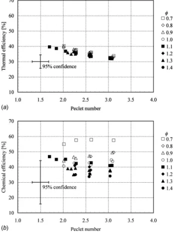
T ¯0.75 m˙ 共14兲Using Eq.共14兲, Peclet numbers are evaluated based on the mea-sured T¯ and m˙, and plotted versus the total mass flow rate in Fig. 9. As stated earlier, the Peclet number decreases with the mass flow rate mainly due to the reduction in the flow residence time. Its dependency on temperature is weak relative to mass flow rate; consequently, the Peclet number is only a weak function of equivalence ratio in the liquid-fueled microcombustor.
The chemical efficiency and the thermal efficiency can also be plotted as functions of the Peclet number as in Fig. 10. Although there are broad uncertainty bands, Fig. 10 displays a few general trends. First, increasing Peclet numbers generally result in de-creasing thermal efficiencies. This is because high Peclet numbers represent low mass flow rates共Fig. 9兲, and the thermal efficiencies have a tendency to increase with the mass flow rate as shown in Fig. 8. The impact of the Peclet number on chemical efficiencies
is unclear in this plot. However, it can be said that low Peclet numbers do not significantly reduce the chemical efficiency, which suggests that the device is not chemically limited in this mass flow rate range, i.e., the device has enough catalyst in the combustion chamber.
Second, chemical efficiencies decrease as the equivalence ratio is increased, whereas thermal efficiencies are not influenced by the equivalence ratio. This is likely because the thermal efficiency is most strongly associated with the heat transfer characteristics of the device. Other parameters that may impact the efficiencies, such as catalyst geometry, fuel diffusion characteristics, pressure, temperature, and mass flow rate, are lumped in the Peclet number. Figure 11 diagrammically explains how the relevant parameters can be grouped into nondimensional parameters. In brief, the
Fig. 10 JP8 combustion result:„a… thermal efficiency and „b…
chemical efficiency versus Peclet number
Fig. 11 Relevant parameters divided into nondimensional
parameters
Fig. 9 JP8 combustion result: Peclet number versus mass
chemical efficiency is a function of the Peclet number and the equivalence ratio, and the thermal efficiency is a function of the Peclet number and the thermal boundary conditions 共fluid-structure interaction characteristics兲 of the specific device.
The experiment-based Peclet numbers are mapped out on a nondimensional space in Fig. 12. The vertical axis represents the chemical efficiency and the horizontal axis represents the thermal efficiency. The product of the two is the overall efficiency, which is also shown in the figure. All the experimental data are plotted in the chemical efficiency-thermal efficiency plane, and each data point has a corresponding Peclet number although the exact value is not marked in the plot for the sake of legibility. Instead, shown in Fig. 12 are the lines of constant Peclet numbers, which were generated by fitting the experiment-based Peclet numbers with the least-squares method.6The average error7of the least-squares fit-ting was 12.4%. Because the thermal efficiency depends on the thermal boundary conditions, the nondimensional operating map 共Fig. 12兲 is device-specific. However, unless the thermal boundary conditions are drastically different, this map can also be used as a design tool to predict the performance of catalytic microcombus-tors over a range of combustor volumes. For example, once design parameters such as mass flow rate, equivalence ratio, and exit gas temperature are specified, the required overall efficiency can be computed using Eq. 共5兲. For a catalytic combustor, it is known that the structural temperature is similar to or slightly lower than the exit gas temperature, so the structural temperature can be es-timated with reasonable accuracy. Then, assuming a proper value for the surface area, the total heat loss can be estimated using a simplified heat transfer model such as the one described in Ref. 关20兴. Then, the overall efficiency can be broken down into the thermal and chemical components, and the operating point can be located on the nondimensional operating map, allowing the de-signer to read the corresponding Peclet number. Using this Peclet number, as well as the desired mass flow rate and exit gas tem-perature, the combustor volume can then be determined from Eq. 共14兲.
5 Partially Filled Catalyst Configuration
Although the use of a catalytic insert extends mass flow rate capability, exit gas temperatures tend to be lower than for gas-phase combustion. Moreover, the exit gas temperature require-ment of 1300 K is so close to platinum’s melting point that the structural integrity of the catalytic insert becomes an issue for the
catalytic microcombustor. Therefore, catalytically anchored gas-phase combustion, or hybrid combustion, was explored关15兴. This concept has been adopted in some conventional gas turbine com-bustors, especially in ground-based power generators, due to ad-vantages in ignition, stability, and emissions关22–26兴. Because the flammability limit of hydrocarbon fuels is rather narrow around the stoichiometric equivalence ratio, conventional gas-phase com-bustors have a fuel-rich primary zone followed by a diluted sec-ondary zone, which cools the combustion products with dilution air to a safe operating temperature for the turbine. Due to elevated combustion temperatures, the primary zone produces NOx emis-sions. Catalytic combustors, on the other hand, can reduce NOx emissions by burning uniform lean fuel-air mixtures at lower tem-peratures. Unlike conventional applications, however, the concept of catalytically anchored gas-phase combustion was proposed for the liquid-fueled microcombustor to achieve both high reaction rates and high exit gas temperature without jeopardizing the cata-lyst. To test this configuration, only the front two-thirds of the combustor volume, instead of the entire combustor, were filled with a catalytic insert.
5.1 Temperature Response. With the combustion chamber
only partially filled with catalyst, JP8 combustion was stabilized in the device at a mass flow rate as high as 0.2 g/s at which point the combustion blew out. Figure 13 shows the temperature re-sponse from the experiment. Unlike the filled catalytic combustor results, there is a fairly large discrepancy between the exit gas temperature and the structural temperature, suggesting that this configuration can provide better thermal isolation of the combus-tion chamber and thus, higher thermal efficiencies. The efficiency breakdown will be discussed in Sec. 5.2. The maximum exit gas temperature obtained was 723 K 共m˙=0.07 g/s兲, and due to the extended mass flow rate, the maximum power density was 54 MW/m3共m˙=0.2 g/s兲, the best achieved in the device. How-ever, the operational requirement of 1300 K was still not met. It appears that the combustion process did not transition to gas-phase combustion even though the fuel-air mixture was at a tem-perature higher than the gas-phase autoignition temtem-perature 共typi-cally 520 K at 1 atm兲. This inhibition of gas-phase ignition has been reported by other researchers, including Dupont et al.关27兴 and Griffiths et al.关28兴. Using methane, Dupont et al. 关27兴 found that heterogeneous catalytic combustion prevailed up to 1400 K. The inhibition of gas-phase ignition was attributed to the deple-tion of fuel species in the gas. Griffiths et al.关28兴 explained the inhibition to be also associated with water vapor desorbed from the catalytic surfaces. The large amount of water vapor prevents favorable conditions for gas-phase ignition by catalyzing reaction paths that consume the free radicals H and CH3, and form more stable species such as HO2and C2H6.
6
After inspecting the trend of the Peclet number distribution, a form of Pe =共a/thermal兲+共b/chemical兲 was used, then coefficients a and b were determined by
the least square method. The map shows regions of both interpolation and extrapolation.
7
Err=
冑
1/n兺k=1 n 关1−共a/thermal,k+ b/chemical,k兲/Pek兴2
Fig. 12 JP8 combustion result: lines of constant Peclet num-bers on a chemical efficiency and thermal efficiency plane
Fig. 13 Partially filled catalytic microcombustor result: tem-peratures versus mass flow rate for= 0.9
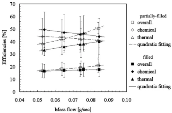
5.2 Efficiency Breakdown. Figure 14 shows the overall,
chemical, and thermal efficiencies as functions of the mass flow rate for an equivalence ratio of 0.9. The large difference between the exit gas temperature and the structural temperature, as noted in Sec. 5.1, results in enhanced thermal efficiency. Since conductive heat transfer from the catalytic insert to the structure is reduced due to smaller contact area, heat can be retained in the fluid better. However, due to the inhibition of gas-phase ignition, the noncata-lytic portion of the combustion chamber cannot be actively used, which results in the reduction of the effective volume of the com-bustor. Therefore, the performance of the combustor is chemically limited at high mass flow rates, i.e., the chemical efficiency de-clines with the mass flow rate, and eventually the reactions are blown out. This will be discussed in more detail using nondimen-sional parameters in Sec. 6.
6 Device Comparison
As discussed in Sec. 5, the partially filled catalytic combustor has relatively higher exit gas temperatures and lower structural temperatures. Figure 15 depicts these trends. This result is attrib-uted to different components of the efficiencies that are presented in Fig. 16. As seen in Fig. 16, the filled catalytic device has lower overall efficiencies even though it has higher chemical efficien-cies. This is due to much lower thermal efficienefficien-cies. In other words, the filled catalytic device has more catalyst in it, so it can combust more fuel. However, due to the presence of a large con-tact area between the catalyst and the sapphire structure, it loses more heat, and the overall efficiency is reduced.
Figure 17 presents these results from an alternate perspective. It shows the chemical efficiencies of the filled catalytic device and the partially filled device for the equivalence ratio of 0.9. Besides the two solid curves for each device, a new curve was generated and is shown in a broken line. This additional curve plots the chemical efficiency of the partially filled device versus the Peclet number, but the Peclet number was recalculated based on a vol-ume that is occupied by the catalyst共1 cm3兲, not the entire com-bustion chamber 共1.4 cm3兲. Then, the new curve fits quite well with the filled device. This indicates that the reduction of the catalyst caused the effective combustor volume to decrease.
The two devices can also be analyzed on the nondimensional operating map. In Fig. 18, two data points are presented, one representing the filled catalytic combustor and the other represent-ing the partially filled one. They are both for a mass flow rate of 0.08 g/s and an equivalence ratio of 0.9. With these same operat-ing conditions, the Peclet number 共based on the actual catalyst volume兲 for the partially filled device is smaller due to a shorter residence time-scale. And because there is less catalyst, the chemical efficiency is also reduced for the partially filled device.
However, the increased thermal efficiency overcomes the reduc-tion in the chemical efficiency, and the overall efficiency becomes higher compared with the filled device.
7 Conclusion
A liquid-fueled microcombustor was designed, fabricated, and experimentally characterized as a part of the MIT microengine research program. It was demonstrated that a liquid-fueled com-bustion system may be feasible for microscale engines, although further development is required. With the combustion chamber entirely filled with a catalyst, JP8 combustion was sustained stably at mass flow rates up to 0.1 g/s, at which point the structure failed
Fig. 14 Partially filled catalytic microcombustor result: effi-ciencies versus mass flow rate for= 0.9
Fig. 15 Device comparison:„a… exit gas temperatures and „b… structural temperatures versus mass flow rate for= 0.9
Fig. 16 Efficiency breakdown comparison between the filled
due to thermal stresses. An exit gas temperature of 780 K and an overall combustor efficiency of 19% were achieved.
The combustor was also tested with just two-thirds of the vol-ume filled with a catalyst, expecting that this configuration could provide extended mass flow rate capabilities like a catalytic com-bustor, as well as high exit gas temperatures like a gas-phase combustor. However, gas-phase ignition could not be achieved in the partially filled combustion chamber. We believe that the cata-lytic combustion inhibited gas-phase ignition. Instead, the perfor-mance resembled a catalytic combustor with two-thirds of the original volume. Therefore, the performance was limited mainly by insufficient flow residence time at high mass flow rates. This configuration resulted in a maximum mass flow rate of 0.2 g/s and a corresponding exit gas temperature of 640 K, leading to the best power density realized in the device, 54 MW/m3.
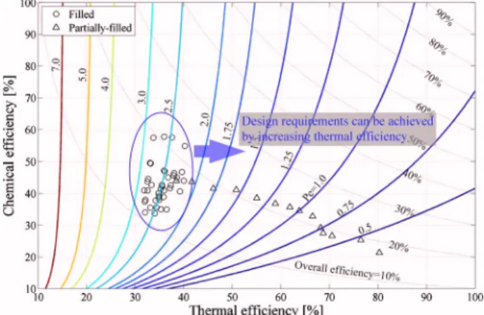
Figure 19 shows the nondimensional operating map for the data obtained from both the filled and partially filled devices. It shows that the filled device has relatively higher chemical efficiencies due to larger catalytic surfaces, whereas the partially filled device provides better thermal efficiencies. This implies that it is possible to achieve the operational requirements without increasing the combustor volume if the filled device has a better thermal isola-tion. One of the ways to do this would be to include a recircula-tion jacket like the propane microcombustor of Spadaccini关15兴. The recirculation jacket is a wrap-around flow path thermally iso-lating the combustion chamber. Minimizing the contact area be-tween the catalyst and the combustor structure by suspending the
catalytic insert on a seat is a possible option as well. Finally, the ability to micromachine materials with higher temperature capa-bilities would be a significant benefit.
The current work focused on maximizing power density rather than achieving high efficiency. Catalytic combustion was a good option for this objective. To make the microengine more practical, however, a high-efficiency liquid-fueled microcombustor must ul-timately be pursued. Since the required exit gas temperature is rather low compared with the adiabatic flame temperature of stoi-chiometric JP8 combustion, the high-efficiency combustor should be operated at low overall equivalence ratios. To efficiently burn JP8 fuel at low equivalence ratios, the combustor must be either a dual-zone combustor or a multistage catalytic-homogeneous hy-brid combustor. Both of these options would require a larger com-bustor volume. Comparing these two comcom-bustor designs and op-timizing between high power density and efficiency will require further research efforts.
Acknowledgment
This research was conducted as part of the MIT microengine project, and the authors thank Alan Epstein for his leadership on this program. They are also grateful to the entire microengine team, especially Chris Spadaccini for his framework on the cata-lytic microcombustor. This work was sponsored by DARPA and the U.S. Army Research Laboratory under the Collaborative Tech-nology Alliance Program Contract No. DAAD19-01-2-0010.
Nomenclature
Roman
Bi ⫽ Biot number
Cb ⫽ bulk concentration 共mol/m3兲
Cp ⫽ constant pressure specific heat of air 共J/kg K兲 Dab ⫽ molecular diffusion coefficient 共m2/s兲
h ⫽ specific enthalpy 共J/kg兲
hf ⫽ heating value of fuel 共J/kg or J/mol兲
M ⫽ molar weight 共g/mol兲 m˙ ⫽ mass flow rate 共kg/s兲
Nu ⫽ Nusselt number
P ⫽ pressure 共Pa or atm兲
Pe ⫽ Peclet number
q ⫽ heat flow 共W兲
R ⫽ gas constant of air 共J/kg K兲
R ⫽ radius 共m兲
ShD ⫽ Sherwood number based on diameter
T ⫽ temperature 共K兲 t ⫽ time 共s兲 V ⫽ volume 共m3兲
Fig. 17 Comparison of chemical efficiencies versus Peclet
number between the filled and the partially filled „with
cor-rected Peclet number… catalytic combustors
Fig. 18 Device comparison on a nondimensional operating
space
Fig. 19 Nondimensional operating map of liquid-fueled
microcombustor
v ⫽ diffusion volume Greek ⫽ efficiency ⫽ density 共kg/m3兲 ⫽ characteristic time 共s兲 ⫽ equivalence ratio Subscripts a ⫽ air D ⫽ diameter f ⫽ fuel References
关1兴 Fernandez-Pello, A., 2002, “Micropower Generation Using Combustion: Is-sues and Approaches,” Proc. Combust. Inst., 29, pp. 883–899.
关2兴 Federici, J., Norton, D., Brueggemann, T., Voit, K., Wetzel, E., and Vlachos, D., 2006, “Catalytic Microcombustors With Integrated Thermoelectric Ele-ments for Portable Power Production,” J. Power Sources, 161, pp. 1469–1478. 关3兴 Nielsen, O., Arana, L., Baertsch, C., Jensen, K., and Schmidt, M., 2003, “A Thermophotovoltaic Micro-Generator for Portable Power Applications,” 12th International Conference on Solid State Sensors, Actuators and Microsystems. 关4兴 Sprague, S., Park, S.-W., Walther, D., Pisano, A., and Fernandez-Pello, A., 2007, “Development and Characterisation of Small-Scale Rotary Engines,” International Journal of Alternative Propulsion, 1共2/3兲, pp. 275–293. 关5兴 Aichlmayr, H., Kittleson, D., and Zachariah, M., 2002, “Miniature Free-Piston
Homogeneous Charge Compression Ignition Engine-Compressor Concept— Part I: Performance Estimation and Design Considerations Unique to Small Dimensions,” Chem. Eng. Sci., 57共19兲, pp. 4161–4171.
关6兴 Dahm, W., Ni, J., Mijit, K., Mayor, R., Qiao, G., Benjamin, A., Gu, Y., Lei, Y., and Papke, M., 2002, “Micro Internal Combustion Swing Engine共MICSE兲 for Portable Power Generation Systems,” 40th AIAA Aerospace Science Meeting. 关7兴 Epstein, A., Senturia, S., Al-Midani, O., Anathasuresh, G., Ayon, A., Breuer, K., Chen, K.-S., Enrich, F., Esteve, E., Frechette, L., Gauba, G., Ghodssi, R., Groshenry, C., Jacobson, S., Kerrebrock, J., Lang, J., Lin, C.-C., London, A., Lopata, J., Mehra, A., Mur Miranda, J., Nagle, S., Orr, D., Piekos, E., Schmidt, M., Shirley, G., Spearing, S., Tan, C., Tzeng, Y.-S., and Waitz, I., 1997, “Micro-Heat Engines, Gas Turbines, and Rocket Engines,” 28th AIAA Fluid Dynamics Conference, Paper No. 97-1773.
关8兴 Epstein, A., Jacobson, S., Protz, J., and Frechette, L., 2000, “Shirtbutton-Sized Gas Turbines: The Engineering Challenges of Micro High Speed Rotating Machinery,” Proceedings of the Eighth International Symposium on
Transpor-tation Phenomena and Dynamics of Rotating Machinery.
关9兴 Jacobson, S., 1998, “Aerothermal Challenges in the Design of a Microfabri-cated Gas Turbine Engine,” 29th AIAA Fluid Dynamics Conference, Paper No. 98-2545.
关10兴 Waitz, I., Gauba, G., and Tzeng, Y.-S., 1998, “Combustor for Micro Gas
Tur-bine Engines,” ASME J. Fluids Eng., 120共1兲, pp. 109–117.
关11兴 Mehra, A., Zhang, X., Ayon, A., Waitz, I., Schmidt, M., and Spadaccini, C., 2000, “A Six-Wafer Combustion System for a Silicon Micro Gas Turbine Engine,” J. Microelectromech. Syst., 9共4兲, pp. 517–527.
关12兴 Mehra, A., and Waitz, I., 1998, “Development of a Hydrogen Combustor for a Micro-fabricated Gas Turbine Engine,” The Solid-State Sensor and Actuator Workshop, Hilton Head Island, SC.
关13兴 Spadaccini, C., Mehra, A., Lee, J., Zhang, X., Lukachko, S., and Waitz, I., 2003, “High Power Density Silicon Combustion Systems for Micro Gas Tur-bine Engines,” ASME J. Eng. Gas TurTur-bines Power, 125, pp. 709–719. 关14兴 Spadaccini, C., Zhang, X., Cadou, C., Miki, N., and Waitz, I., 2003,
“Prelimi-nary Development of a Hydrocarbon-Fueled Catalytic Micro-Combustor,” Sens. Actuators, A, 103, pp. 219–224.
关15兴 Spadaccini, C., Peck, J., and Waitz, I., 2007, “Catalytic Combustion Systems for Microscale Gas Turbine Engines,” ASME J. Eng. Gas Turbines Power,
129, pp. 49–60.
关16兴 Lefebvre, A., Freeman, W., and Cowell, L., 1986, “Spontaneous Ignition De-lay Characteristics of Hydrocarbon Fuel/Air Mixtures,” NASA Technical Re-port No. 175064.
关17兴 Dodds, W., and Bahr, D., 1990, Combustion System Design, Design of Modern
Gas Turbine Combustors, Academic, New York.
关18兴 Heywood, J., 1998, Internal Combustion Engine Fundamentals, McGraw-Hill, New York.
关19兴 Hayes, R., and Kolaczkowski, S., 1997, Introduction to Catalytic Combustion, Gordon and Breach, New York.
关20兴 Peck, J., 2008, “Development of a Liquid-Fueled Micro-Combustor,” Ph.D. thesis, Massachusetts Institute of Technology, Cambridge, MA.
关21兴 Kerrebrock, J., 1992, Aircraft Engines and Gas Turbines, MIT, Cambridge, MA.
关22兴 Dalla Betta, R., Schlatter, J., Yee, D., Loffler, D., and Shoji, T., 1995, “Cata-lytic Combustion Technology to Achieve Ultra Low NOx, Emissions: Catalyst Design and Performance Characteristics,” Catal. Today, 26共3–4兲, pp. 329– 335.
关23兴 Dalla Betta, R., 1997, “Catalytic Combustion Gas Turbine Systems: The Pre-ferred Technology for Low Emissions Electric Power Production and Co-Generation,” Catal. Today, 35共1–2兲, pp. 129–135.
关24兴 Dalla Betta, R., and Rostrup-Nielson, T., 1999, “Application of Catalytic Com-bustion to a 1.5 MW Industrial Gas Turbine,” Catal. Today, 47共1–4兲, pp. 369–375.
关25兴 Beebe, K., Cairns, K., Pareek, V., Nickolas, S., Schlatter, J., and Tsuchiya, T., 2000, “Development of Catalytic Combustion Technology for Single-Digit Emissions From Industrial Gas Turbine,” Catal. Today, 59共1–2兲, pp. 95–115. 关26兴 Carroni, R., Schmidt, V., and Griffin, T., 2002, “Catalytic Combustion for
Power Generation,” Catal. Today, 75共1–4兲, pp. 287–295.
关27兴 Dupont, V., Zhang, S.-H., and Williams, A., 2002, “High-Temperature Cata-lytic Combustion and Its Inhibition of Gas-Phase Ignition,” Energy Fuels,
16共6兲, pp. 1576–1584.
关28兴 Griffiths, J., Hughes, K., and Porter, R., 2005, “The Role and Rate of Hydro-gen Peroxide Decomposition During Hydrocarbon Two-Stage Autoignition,” Proc. Combust. Inst., 30, pp. 1083–1091.