Publisher’s version / Version de l'éditeur:
Vous avez des questions? Nous pouvons vous aider. Pour communiquer directement avec un auteur, consultez la
première page de la revue dans laquelle son article a été publié afin de trouver ses coordonnées. Si vous n’arrivez pas à les repérer, communiquez avec nous à PublicationsArchive-ArchivesPublications@nrc-cnrc.gc.ca.
Questions? Contact the NRC Publications Archive team at
PublicationsArchive-ArchivesPublications@nrc-cnrc.gc.ca. If you wish to email the authors directly, please see the first page of the publication for their contact information.
https://publications-cnrc.canada.ca/fra/droits
L’accès à ce site Web et l’utilisation de son contenu sont assujettis aux conditions présentées dans le site LISEZ CES CONDITIONS ATTENTIVEMENT AVANT D’UTILISER CE SITE WEB.
Technical Translation (National Research Council of Canada), 1967
READ THESE TERMS AND CONDITIONS CAREFULLY BEFORE USING THIS WEBSITE. https://nrc-publications.canada.ca/eng/copyright
NRC Publications Archive Record / Notice des Archives des publications du CNRC :
https://nrc-publications.canada.ca/eng/view/object/?id=cc12207a-4fe7-4927-8f24-7d9a04d327fb https://publications-cnrc.canada.ca/fra/voir/objet/?id=cc12207a-4fe7-4927-8f24-7d9a04d327fb
Archives des publications du CNRC
For the publisher’s version, please access the DOI link below./ Pour consulter la version de l’éditeur, utilisez le lien DOI ci-dessous.
https://doi.org/10.4224/20386547
Access and use of this website and the material on it are subject to the Terms and Conditions set forth at
Instructions for designing bearing media and foundations in the
southern zone of the permafrost region
This translation of the Soviet Building Code dealing with the design of foundations for the southern zone of the permafrost region is of particular interest to the Division of Building Research in its investigations of permafrost and building problems in northern Canada. A similar document dealing with the design of foundations for the entire perma-frost region was translated in 1962 - "Technical Considerations in Designing Foundations in Permafrost" (NRC Technical
Trans-lation 1033). The Russians have been involved in construction
on permafrost for many years in Siberia and their experiences are of great interest to those who are tnvolved in this activity in northern Canada. A building code for northern Canada is currently being prepared.
Comments upon the contents of this translation from any who have had experience with building in permafrost areas will
be welcomed by the Division. Such mutual exchange of
informa-tion will be of great assistance to the Division in its task of providing essential information, especially upon unusual building problems, for use by the entire building industry of Canada.
The Division is grateful to Mr. V. Poppe of the Trans-lations Section, National Research Council, for translating this document and to Dr. R.J.E. Brown of this Division who checked the translation.
Ottawa
September 1967
R.F. Legget Director
Title:
Publisher:
Translator:
Technical Translation 1298
Instructions for designing bearing media and foundations in
the southern zone of the permafrost region. Academy of
Con-struction and Architecture U.S.S.R. Research Institute of
Foundations and Underground Structures
(Ukazaniya po proektirovaniyu osnovanii i fundamentov dlya
yuzhnoi zony rasprostraneniya vechnomerzlykh gruntov. Akademiya
Stro tel'stva i Arkhitektury SSSR. Nauchno-Issledovatel'skii Institut Osnovanii i Podzemnykh Sooruzhenii)
Gosizdat. Lit. po Stroitel'stvu, Arkhitekture i Stroitel'nym
Materialam. Moskva, 1962
(State Publishing House of Literature on Building, Architecture
and Building Materials. Moscow, 1962. 77p.)
There are a number of terms in this Russian building code which are difficult to translate precisely into English. These notes are designed to clarify these terms and other features of the original Russian text. It must be remembered that Russian literary style is somewhat different from English so that various passages in the translation may appear somewhat stilted from our standards. Nevertheless, this translation is as close to the intended meaning as the translator thinks possible.
1. The metric system is used throughout the document.
2. All temperatures are in degrees Centigrade. The terms "positive temperatures" and "negative temperatures" refer therefore to tem-peratures above and below OOC (32°F), respectively.
3. To avoid any possible confusion, the symbols used in the mathemat-ical formulae are reproduced exactly as they appear in the original Russian text.
4.
The terms "merging permafrost" and "non-merging permafrost" are not used in English. "Merging permafrost" refers to the situation where the seasonally frozen ground extends down to the permafrost. "Non-merging permafrost" refers to the situation where the seasonally frozen ground does not extend down to the permafrost leaving a layer of thawed ground between the two layers of frozen ground.5. The terms "sandy loam" and "clay loam", which appear in several places in the translation, are not used in English language engineer-ing documents. These terms are, however, the most convenient trans-lations for the two Russian terms which are used commonly in their soil mechanics and soil science literature. The Russian terms and their dictionary meanings are:
(i)
(ii)
supesok sandy loam, soil containing 60 - 80% sand.
suglinok clay loam, argillaceous soil, clayey soil, loam, soil containing sand and 25 - 50% clay. The Swedish definition" for this term is - fine and medium, poorly sorted silt.
It is left to the user's discretion to decide which translation is most suitable for his requirements.
6.
The term "bearing medium" is used in the Canadian National Building Code to refer to the soil which lies immediately beneath the build-ing foundation. The Russian term "osnovanie" has various meanings such as "base", "foundation", "foundation sail", etc. but the term "bearing medium" is used in this translation to avoid confusion with other "foundation" terms.7.
There is some difficulty in differentiating among the various Russian soil mechanics terms for "compaction", "consolidation", "compression", "compressibility", "contraction", etc. There are six Russian wordsRussian Word (i) szhatie (ii) szhimaemost' (iii) obzhatie (iv) obzhimaemyi (v) plotnost I (vi) uplotnenie Designated Symbol Cl C2 01 02 pl p2 Dictionary Meanings condensation, compression, constriction, contraction, reduction, shrinkage compressibility, condensibility, contractibility squeezing, pressing, compression squeezed, pressed, compressed density, thickness, consistency, massiveness, solidity, toughness, compactness condensation, thickening, compression, squeezing, contraction, shrinkage, packing, settling, flattening, consolidation, compaction
The meaning that is underlined is the one used most commonly in the
translation. This does not preclude the fact that another English word might
give a closer approximation of the intended meaning. For convenience, the designated symbols Cl, C2, etc. are included in the translation in brackets after the term in question to indicate which Russian word was used in the
original document. Therefore, the user is at liberty to employ another
foundations in the southern zone of the permafrost region" are based on "Technical considerations in designing founda-tions in permafrost" (SN 91-60) and represent a further development of the latter; they have been produced in con-junction with the Gosstroi, uNsNsNrセ
The Instructions have been developed by Doctor of Technical Sciences V.P. Ushkalov at the Research Institute of Foundations and Underground Structures, Academy of Con-struction and Architecture, U.S.S.R.
A detailed description of calculation methods and def-initions of design characteristics of bearing media and foun-dations may be found in "Investigation of performance of
thawing bearing media and their design on the basis of ultimate deformation of structures" by V.P. Ushkalov, Izd. Akad. Nauk SSSR, Moscow, 1962.
The present instructions have been compiled by consid-ering comments received from 22 design, research and con-struction establishments: Institute of Permafrost Studies, Academy of Construction and Architecture, U.S.S.R.; Central Construction Research Institute, Ministry of Transportation Construction; State Institute for Highway Research, Ministry of Transportation Construction; Leningrad Marine Research and Planning Institute, Ministry of the Merchant Fleet; Krasnoyarsk Construction Research Institute, R.S.F.S.R.; Far Eastern Con-struction Research Institute, R.S.F.S.R.; Gosstroi, R.S.F.S.R.; Petrovsk-Zabaikal'skii Metallurgical Works; Railroad Research Institute, Ministry of Railroads; V.V. KUibyshev Moscow Institute of Civil Engineering; Novosibirsk Institute of Civil Engineering; Leningrad Institute of Civil Engineering; Vorkuta Planning and Research Administration; northern branch of the Institute of Permafrost Studies; Khabarovsk Institute of Railroad Engineering; Chita Branch of the Planning Institute of Non-ferrous Metals; Pechora Institute of Coal Research, etc.
The instructions have been examined and approved by the Board of the Institute of Foundations and Underground Structures, Academy of Construction and Architecture, U.S.S.R. and are rec-ommended as a practical aid in engineering and geological work, as well as in the design, construction and operation of buildings and other structures on permafrost.
Introduction " " Symbols used . . . • . . . .
7
8 I. General r u l e s . . . 12 II. Main definitions... . . . .. 13
III. Physical characteristics of foundation soils 16
IV. Thermophysical characteristics of soils 19
V. Use of soils as bearing media and methods of maintaining their
rated perennially frozen state 23
VI. Design of bearing media in relation to deformation '" 26
VII. Additional requirements concerning structural design of
structures and their foundations
4
2VIII. Additional requirements for bearing media and foundations of
large section and large panel buildings and structures 46
IX. Additional requirements for the maintenance of buildings and
structures and their bearing media
48
X. Sample c a l c u l a t i o n s . . . 49 Appendices: I. General characteristics of the southern zone of the
permafrost r e g i o n . . . 57 II. Mechanical properties of thawing soils and their
determination... 64
III. Map of the southern zone of the permafrost region
These instructions are based on the results of comprehensive investiga-tions of construction properties and performance of bearing media and founda-tions in the southern zone of the permafrost region. The purpose of these investigations was as follows:
1) to determine the dependence of thermal properties and compressibility
(C2)
of soils on their physical properties and develop more rapid methods of determining the design factors;2) to determine changes in thermal processes in thawing perennially
fro-zen foundation soils with time and develop engineering methods of determining depth and rate of thawing of frozen soils beneath a structure under conditions of controlled heat exchange;
3)
to determine the distribution of pressure from foundations inthaw-ing permafrost and construction of design diagrams;
4) to study the settlement of foundations in thawing permafrost and the heaving of foundations during soil freezing in the active layer in its natural state, and develop methods of calculating their values and rates;
5)
to study actual deformation due to settlement and frost heaving of foundations and determine their ultimate values from the condition of build-ings and structures of different rigidity.Up-to-date methods of designing bearing media on the basis of the ultimate conditions of structures, not only with reference to the settlement of founda-tions but also to deformation due to heaving, applied in the U.S.S.R. for the first time, were developed further and incorporated into the instructions.
The instructions also contain additional requirements concerning the design of structures and their foundations, additional instruction for design-ing natural and artificial ventilation of external elements of a structure, instructions for utilizing thawing permafrost as a bearing medium in construc-tion of large secconstruc-tion and large panel buildings, as well as regional charac-teristics of the southern zone of the permafrost region, and other information of use in construction in the southern zone which was not included in "Techni-cal Considerations In Designing Foundations In Permafrost" (SN 91-60).
W - natural moisture content 0f soil in
%
or as fractions of unit dry W 11.0 W 11 W 11.0 W06
W P weight of soil;W -
content by weight of unfrozen water in unit volume of frozen soil;H
- content by volume of unfrozen groundwater as a fraction; - ice content by weight in unit volume of frozen soil; - ice content by volume as a fraction;
- moisture content of soil by volume in
%
or as a fraction;- moisture content at the plastic limit as a fraction determined accord-ing to GOST
5183-49;
W -
moisture content at the liquid limit determined according to TGOST
)184-49;
W -
plasticity index as a fraction;n
k coefficient denoting unfrozen water content in clay soils (see
B
of soil skeleton in g/cm3 or tim3 ;
of • 1
skeleton in natural frozen state in g/cm3 tim
3 ;
SOl.l. or
of soil skeleton thawed under given pressure in g/cm3 or
Y
T - unit weight tim3 ; Table IV); y unit weight CK y. - unit we ight ェ|セQmentally according to GOST
5181-49;
of water in g/cm3 or t/m3;
of mineral soil particles in g/cm3
determined
experi-Y . -
unit weight of undisturbed soil skeleton determined experimentally inuD
g/cm3 or t/m3; Y - specific weight D y - specific weighty
B - consistency of clay soils;
g - saturation of soil pores with ice and unfrozen water (extent of sat-uration with moisture);
n - porosity of frozen ground as a fraction;
E - coefficient of porosity of frozen soil;
ゥカセ
E - minimum coefficient of porosity of sandy soil determined
experimen-i.; LUI
tally;
- coefficient of porosity of clay soil with moisture content at the plastic limit;
R - compactness of frozen coarse detritus and frozen sandy soils; A - coefficient of thermal conductivity of frozen soil in kcal/m/hr/oC
M
determined from data in Table V; in the case of clay soils in the phase trarlsition zone, allowances should be made also for the unfrozen water content W
t
o
A - coefficient of thermal conductivity of thawed soil in kcal/m/hr/oC
T
determined from data in Table V;
C - heat capacity by volume of soil in kcal/m3 / o C ;
06
C - heat capacity of frozen soil in kcal/m3/oC determined from data in
セNセ
Table V; in the case of clay soils in the phase transition zone, it is necessary to take into account the unfrozen water content;
C - heat capacity of thawed soil in kcal/m3 / o C ;
'1'
C - specific heat capacity of soil in kcal/kg/oC;
IT
C J _ same of frozen soil in kcal/kg/oC;
y.M
C - same of thawed soil in kcal/kg/oC;
y.
'rC - same of soil skeleton in kcal/kg/oC determined experimentally;
y.c
C - same of water in kcal/kg/oC;
y.B
C - same of unfrozen water in kcal/kg/oC;
y.l!
°
セ - same of ice in kcal/kg/ C;
y.J1
a - coefficient of thermal diffusivity of frozen soil in m2 / h , determined M
from data in Table V; in the case of clay soils in the phase transi-tion zone it is essential to consider also the unfrozen water content; a - coefficient of thermal diffusivity of thawed soil in m2 / h , determined
T
from data in Table V;
a - coefficient of heat transfer at the internal surface of enclosure in
n
kcal/m2 / h r / d e g determined according to specifications SNiP, Chapter 11-B.3, Tables IV and V;
a - same for external surface of enclosure in kcal/m2 / h r / d e g ; II
t - estimated temperature of air at the floor surface level of the
build-n
ing in degrees;
- estimated temperature of frozen soil over many years at the depth of zero amplitude, determined from observations, in degrees;
t - mean annual temperature of the permafrost layer from its upper surface
M
to the depth of zero amplitude, in degrees;
h - depth of thaw of frozen soil beneath the centre of the building or
C
structure over a given period of time, taking into account its outline form and dimensions in metres;
h - same beneath the edge of the building or structure in metres;
H
h - maximum depth of thaw of frozen soil beneath the centre of the building
C.lIC
or structure in metres;
V
c - rate of thawing of soil in m/year;
v - maximum rate of thawing of frozen soil beneath the centre of the
build-c.np
ing or structure in m/year;
T - thawing time of foundation soil from the beginning of occupancy of the building or structure in hours;
T
S estimated period of thaw stabilization in hours; see section 66;
q - latent heat of thawing of frozen soil equal to W
JI O • P • YB in kcal/m3 ;
P - latent heat of melting of ice, taken to be 80 kcal/kg;
k - correction factor which takes into account the effect of the thermal
T
regime of the building or structure in relation to their dimensions; determined from data in Table
VII;
K
-
proportionality factor in formula (27), section 67, taken to be 0.65 cin the middle permafrost zone and 0.8 in the southern zone;
0i - thickness of individual protective layers (first storey or basement floor and thermal insulation of soil surface beneath the floor) in
R
np
s
no
np
metres;- corrected thickness of thermal insulation of the floor in metres; - corrected thickness of insulation layers in m, required for reducing
the depth and rate of thawing to given maximum value;
thermal resistance of the i-th layer of thermal insulation in m2/hr/ de g/ kcal;
- thermal resistance of thermal insulation of protecting structure re-quired for reducing the depth and rate of thawing to permissible value in m2/hr/deg/kcal;
e - relative compression (Cl) of soil thawing under pressure;
e - degree of settlement of thawing soil (relative compression (Cl) of
n
soil thawing under pressure of 1 kg/cm 2);
A -
coefficient of thawing;a - coefficient of compaction (p2) in cm 2/kg;
セ - settlement of foundation in a given period of time in em;
length of structure in metres; B - width of structure in metres;
セ - average maximum settlement in em;
cp
l - twisting as a fraction of span;
f - relative bending as a fraction of span;
a
z - thickness of compressed layer in metres;
セ - pressure beneath the foundation base in kg/cm 2;
D pressure from the foundation in the i-th layer of soil in kg/cm2;
\f,i
-Pi - pressure due to its own weight in the i-th layer of thawing soil in kg/cm 2;
v - rate of settlement in em/year;
s
v - maximum rate of settlement in em/year;
H - height of structure in metres; ィセ - depth of foundation in metres; a,b - sides of foundation in metres;
E - modulus of general deformation of thawing layer of soil in t/m2;
r
E - corrected modulus of deformation of material of bearing structures in K
t/m2;
R - coefficient of three-dimensional strength of structure;
n
K - rigidity factor of structure;
m
I. GENERAL RULES
1. These instructions are intended for guidance in the design of
bear-ing media and foundations of buildbear-ings and industrial structures in the southern zone of the permafrost region shown on the enclosed map (Appendix III); regional characteristics are given in Appendix I.
2. The instructions represent further development of and supplement to
existing All-Union Technical Considerations SN 91-60. They account more fully
for the peculiarities of the interaction between bearing media and foundations on perennially frozen soils in the southern zone, characterized by relatively high temperature, presence of thawed layers, settlement on thawing and heaving of soil of the active layer on freezing.
3.
All methods incorporated in Technical Considerations SN 91-60 andgiven in section 51 may be applied when using permafrost in the southern zone
as a bearing medium. When applying Method III (allowances for thawing of the
soil during the life span of a structure) it is essential to maintain the depth and rate of thawing within acceptable limits.
4. Design of bearing media and foundations 'on permafrost in the southern zone, as a rule, must be based on ultimate deformation of structures due to settlement as well as frost heaving of foundations; this requirement forms the basis of the present Instructions.
5.
Natural bearing media should consist, if possible, of thawed ground, rock, soils not sUbject to settlement or subject to very little settlement, coarse-grained soils, or sandy and clayey, perennially frozen soils which on thawing are subject to settlement not detrimental to a given structure, or non-heaving soils of the active layer.6.
Interaction between heaving soil of the active layer and the founda-tion, as well as between a heat-emitting structure and frozen foundation soil, lead to frost heaving of the foundation, thawing and settlement of frozen foundation soil accompanied by a more or less considerable deformation of the structure, which depends on the extent and rate of its development. Therefore, when designing the bearing media of structures on permafrost, i t is essential to consider not only the effects of load and temperature but also of time.7.
Thawing of frozen soil beneath a structure and freezing of soil ofthe active layer during the life span of the structure can be reduced to a certain depth and rate, as defined by the ultimate conditions of the structure, by thermal insulation and ventilation of the foundation base and insulation of the ground surface.
8.
To avoid errors in design which may lead to structural failure. the design of bearing media must contain allowances for their interaction with the structure. This is achieved by confining the deformation of thawing founda-tion soils and of heaving soils of the active layer within certain limits not exceeding the ultimate conditions of stability and operational suitability of structures, and by selecting the optimal values of their rigidity.9.
It is recommended to design bearing media and foundations inperma-frost in the southern zone according to instructions given in paragraph 61. II. MAIN DEFINITIONS
10. The term "perennially frozen soil" can be applied to all types of soil with temperature below or equal to OoC, containing ice inclusions, and which do not thaw in the course of several years,
Permafrost may be continuous with depth or stratified; horizontally it may be continuous or patchy.
11. The active layer is the surface layer of soil which freezes in
win-ter and thaws in summer.
12. Under natural conditions perennially frozen sandy and clay soils may
be divided into three categories: solidly frozen, plastic frozen and loosely
frozen. There are three types of texture: massive, layered and vesicular.
13. Perennially frozen soils are described according to the nomenclature
used for thawed soils (SNiP II-A.IO-62).
14. Construction properties of perennially frozen soils and soils of the
active layer are evaluated according to physico-mechanical characteristics accepted for thawed soils, as well as on the basis of the following additional characteristics related to the texture of frozen soils:
(a) relative contraction (Cl) e (when frozen soil thaws at a given
pres-sure);
(b) degree of settlement of thawing soil en;
(c) conditional settlement of thawing soil mass (section
8);
(d) density (pI) of coarsely fragmented and sandy, solidly frozen and loosely frozen soils R;
(e) consistency of clay soils B.
15. Relative contraction (Cl) of soil thawed at a given pressure is
de-termined according to SN 91-60 by the formula:
e=
(1)
16. Degree of settlement of permafrost e is conditionally determined by
its relative contraction (el) e on thawing under pressure p = 1 kg/cm£:
• _ セtiMtB
セョM • (la)
セti
Soils are said to be: unsusceptible to settlement when en セ 0.03;
susceptible to settlement when 0.03 < e セ 0.1; highly susceptible to settle-n
ment when en > 0.1.
17. Degree of density (pI) is determined by means of formula (2) in SN 91-60 and sections 36 and 38 of these instructions:
( 2 )
Soils are said to be: dense when R セ 0.33; moderately dense when
0.33 < R セ 0.67; loose when 0.67 < R セ 1; very loose when R > 1.
18. The consistency of frozen soils is determined as follows:
The nomenclature of clay soils according to consistency is given in Table I.
Table I
The nomenclature of clay soils according to consistency
Condition of clay soils
Hard .
Semi-hard and hard-plastic .
Soft-plastic . Flowing-plastic . Flowing . Consistency B < 0
o
セB
セ 0.5 0.5 <B
セ 0.75 0.75 <B
セ 1 B > 119. On the basis of settlement of the thawing soil ュ。ウウセ soils may be subdivided into three categories (Table II).
20. Frozen soil and hydrogeological conditions are characterized by: (a) structure, composition and state of perennially frozen soils; (b) temperature and thickness of permafrost and thickness of active layer;
(c) settlement of permafrost on thawing;
(d) frost heaving of soils in the active layer during freezing;
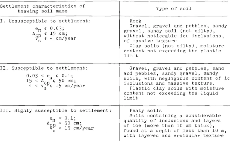
Table II
Settlement characteristics of thawing permafrost Settlement characteristics of
thawing soil mass
I. Unsusceptible to settlement: en セ 0.03;
セ」ー
,
15 em;V
s セ
4
em/yearII. Susceptible to settlement: 0.03 < en セ 0.1;
15 < セセ セ 50 em; 4 < カvpセ 15 em/year
s
III. Highly susceptible to settlement: en > 0.1; セ」ー > 50 em; v > 15 em/year s Type of soil Rock
Gravel, gravel and pebbles, sandy gravel, sandy soil (not silty), without noticeable ice inclusions, of massive texture
Clay soils (not silty), moisture content not exceeding the plastic limit
Gravel, gravel and pebbles, sand and pebbles, sandy セイ。カ・ャL sandy soils, with negligible content of ice inclusions and massive texture.
Plastic clay soils with moisture content not exceeding the liquid limit
Peaty soils
Soils containing a considerable quantity of inclusions and layers of ice (more than 10 em thick), found at a depth of less than 10 m, with layered and vesicular texture
21. In the case of permafrost merging with the freezing active layer, the thickness of the active layer is defined as the maximum possible depth of seasonal thawing, and in the case of non-merging permafrost as the maximum possible depth of seasonal freezing.
The standard thickness of the active layer hH is determined according to
M
section 15, SN 91-60.
In the absence of data on the thickness of seasonal freezing and thawing, the thickness of the active layer is determined by thermo-technical calcula-tions (see section
64).
The standard thickness of the active layer under natural conditions may be tentatively estimated from Table III.
22. The estimated permafrost table is the location of the upper boundary
of permafrost established under the influence of the thermal effect of a building or structure during their operation.
The outline of the calculated surface of thawing foundation soils may be found by determining the extent of thawing beneath the central part and the
edge of a building or structure in a given period of time, as described in sections 62 - 67.
Table III
Standard thickness of active layer
Thickness of active layer in m Moisture content (determined visually)
Low moisture content .
Moist . Saturated . Sandy soil 3 - 4.5 2.5 - 3 1.7 - 2.5 Clay soil 2.5 - 3 2 - 2.5 1.2 - 2
23. Thawing of perennially frozen ice-saturated soils is taken to mean
the transition of such soils from the frozen to the thawed state during which
all ice is converted to water. The depth of thaw of perennially frozen
foun-dation soils is the depth of the lower surface of the layer thawed in a given period of time.
24. Distinction should be made between settlement of/frozen soils on
thawing under pressure and soil subsidence.
Settlement of soils thawing under pressure is deformation on compaction due to their own weight and an external load.
Subsidence is rapid, extensive settlement of soils thawing under pres-sure, accompanied by sharp changes in their structure.
25. Heaving soils include fine sand and silty sand, sandy loam. clay loam and clay, as well as coarsely fragmented soil containing in the matrix more than 30% by weight of particles less than 0.1 mm which freeze under moist conditions (definitions according to SN 91-60).
III. PHYSICAL CHARACTERISTICS OF FOUNDATION SOILS
26. Calculations involving ultimate deformation of buildings or
struc-tures require the introduction of a number of factors defining the properties of thawing permafrost, such as thermo-physical coefficients, coefficients of thawing, compaction (p2), pressure distribution, etc.
This makes it necessary to determine the following physical properties of soils:
(1) specific gravity of mineral soil particles y ; y
(2) natural moisture content of soil W; (3) unfrozen water content in soil W
H ;
(4) unit weight of undisturbed frozen soil セV
;
(5) moisture content at the plastic limit W
(6)
minimum coefficient of porosity for sandy soils £ ; coefficient MVlHof porosity when moisture content 。ーーイッ。」ィセ the plastic limit for clay soils
£W
P 27. Samples for determining physical properties should be taken from
boreholes and test pits in columnar form weighing up to 2 - 3 kg, typical of each individual soil layer and satisfying the accepted requirements.
When the soil is homogeneous in composition, structure and moisture content, the specimens should be taken from the proposed foundation base down to the depth of expected thawing at 0.5 m intervals.
28. The specific gravity of mineral soil particles y , moisture content
y
at the plastic limit Wand at the liquid limit W , and the coefficient of
p T
porosity at the plastic limit £W are determined in the same way as for thawed
soils. p
29. The natural moisture content of frozen soil W is the amount of water in the soil, both in the liquid and solid phases, expressed in percentage dry weight of soil or as a fraction.
In the case of homogeneous, fine-grained frozen soils, the moisture con-tent by weight may be determined by the drying method as suggested for thawed soils in GOST 5179-49.
In the case of heterogeneous frozen soils, it is essential to select at least three specimens from each horizon. Laboratory determination of ュッゥウセオイ・
content should be done at least three times. Ice layers more than 1 mm thick
are counted separately.
In the majority of cases the natural moisture content of soil W deter-mined in the laboratory differs for various reasons from the actual moisture content. Therefore, to avoid errors, it is essential to determine W in the field at the time of determination of the unit weight of soil
Yo6'
30.
The unfrozen water content by weight WH is determined from (Appendix III, SN 91-60):( 4 ) The unfrozen water content by volume is determined as a fraction as follows:
W - WH ' 7..
8.0 - ,
78
Coefficient k
B is determined from Table IV (after A.N. Davydochkin).
31. Ice content by volume in unit volume of frozen soil W
n is determined from the formula:
Table IV
Values of coefficient k B
Plastic limit Values of k with
correspond-Plasticity index of soil ing エ・ュー・イセエオイ・ in degrees
Type of soil Wn W p -0·3 -0.5 -1 -3 -4 Sandy loam 2
-
7 10-
18 0.9 0.8 0.7 0.6 0.5 Clay loam 8-
13 19-
23 1 0.9 0.8 0.7 0.6 Heavy clay loam 14-
17 24-
27-
1.2 1 0.9 0.8 Clay > 17 > 27-
1.4 1.1 1 0.9Ice content by volume is determined from:
Moisture content by volume W
o6 is found from:
U7 - W 1
00 - T.. - ·
T.
32. The degree of soil saturation with ice and unfrozen water is determined from the formula:
( 6 )
(7)
g= I .09 WA.O
+
IWH.On (8 )
33. The coefficient of porosity with moisture content at the plastic
limit is determined from the formula:
34. The unit weight of undisturbed frozen soil Y
o
6
represents the weight of a unit volume of undisturbed frozen soil at a given moisture con-tent.The two recommended methods of determining Y
o
6
are: (a) cutting ring method, and (b) hydrostatic weighing method.35. The moisture content at the plastic limit of clay soil is
deter-mined according to GOST 5183-49.
36. The unit weight of a sandy soil skeleton in the thawed state with maximum density (pl) Y'r.n is determined as the quotient of dry soil weight over its volume in g /cm3
• In determining Y it is essential to
T.n
place slightly moistened sand (of less than capillary moisture content) into a cylinder with a volume of at least 100 cm3
wooden pestle. After drying, the soil is weighed on laboratory scales and the result obtained is divided by the volume of the cylinder.
37.
The minimum coefficient of porosity of sandy soil is determined from the formula:(10 )
38.
The unit weight of a sandy soil skeleton with minimum density (pI) YT•p is found by dividing the weight of air-dried sand loosely packed in the cylinder by the volume of the latter.
IV. THERMOPHYSICAL CHARACTERISTICS OF SOILS
39.
In the absence of filtration the heat transfer in thawing foun-dation soils takes place mainly by contact heat conductivity.The main thermophysical characteristics of soils are the specific and volumetric heat capacities C and C セL coefficient of thermal conductivity
y 00
A,
and coefficient of thermal diffusivity a.The relation between these factors is as follows:
A
Co6= - .
a
(11)
(12)
40. The specific heat capacity of soil may be determined as follows: a) frozen soil:
b) thawed soil
CY•T
=
ICy •c+
W C,.•. (14 )41. According to experimental data, the average specific heat ca-pacities of the components of frozen soil included in formulae (13) and (14) may be taken as follows:
a) mineral skeleton(Cy . .
c):
quartz sand - 0.17, clay loam - 0.19, clay - 0.2 kcal/kg/deg;b) unfrozen water in frozen soil (C ) - 1 kcal/kg/deg;
y.H.
c) ice (C n ) - 0.5 kcal/kg/deg.
y . •
42. Coefficient of thermal conductivity
A
denotes the amount of heat in calories (kcal) passing through 1 cm2 (m2) of a soil layer 1 cm (m) thickin 1 sec (hr) with temperature gradient on ground surface of 1 deg/cm (m). A may be expressed in physical units (cal/cm/sec/deg) or technical units (kcal/m/hr/deg). The conversion factor for converting physical units to technical units is
360.
43.
The coefficient of thermal conductivity of water in the temper-ature range of 0° to 30°C is taken as 0.5 kcal/m/hr/deg.The coefficient of thermal conductivity of ice An in the interval of temperature change (t) from 0° to -80°C is found from:
>"..= 1,908(1 +O,OOI5t)kcal/m/hr/deg.
The coefficient of thermal conductivity of air in the positive tem-perature range is taken as 0.02 kcal/m/hr/deg.
44.
The coefficient of thermal diffusivity a expresses the ability of soil to change its temperature at a given point owing to a changed tem-perature gradient at that point; the larger this coefficient, the faster the cooling or heating of the soil; it is determined from the expression:1.
a = - .
Coa (16)
a may be expressed in physical units (cm£/sec), or technical units (m£/hr). The conversion factor for converting physical units to technical is 0.36.
45.
The rate of thawing of frozen foundation soils depends on their type. phase composition of water contained in them. saturation with ice. initial temperature. and thermophysical properties as well as temperature, form and dimensions of the heat source. It is determined as outlined in section 68.46.
It is recommended to determine the thermophysical coefficients of frozen and thawed soils by methods based on a non-steady state thermal regime:(a) determination of coefficient on the basis of physical properties of soil;
(b) analysis of processes of thawing and freezing of soil; (c) thermal impulse method;
(d) analysis of temperature wave in the soil.
47.
Values of thermophysical coefficients of sandy and clay soils in relation to their physical characteristics (unit weight by セV'
moisture content W, and degree of saturation with moisture g) are found from Table V.Table V
Value of thermophyslcal coefficierlts of salls j.n イ・セオANゥッョ to エセャ・NャャG ptlysical characteristics
Physical characteristics of soils tィ・イュッーィケウセ」。ャ coefficients of soils
soils for +16°e.
Mois t. cont. Thermal conduct. Vo Lumetri c heat Thermal diffusivity Unit wt tim' (ice cont.), of s oiL in capacity of soil of soil in
% Moisture kcal/m/hr/deg in kcal/m'/deg m'/hr
cont. g,
Soil Skeleton By wt. By voI . % Thawed Frozen Thawec:!, Froze!2' Thawed Frozen
YoG Yell W W
"1'
AM CT· I 0 C... 10 c .10' (l .10' 06 Lセi T M Sandy soils 1.1 1.05 4 4 7 0.38 0.42 0.22 0.2 1.73 2.1 1.1 1 8 8 15 0.5 0.62 0.26 0.22 1. 92 2.82 1.2 1.15 4 5 10 0.45 0.53 0.25 0.22 1.8 2.ln 1.2 1.1 8 9 16 0.61 0.76 0.29 0.24 2.1 3.17 1.3 1. 25 4 5 10 0.54 0.64 0.27 0.24 2 2.67 1.3 1.2 8 10 20 0.71 0.9 0.32 0.26 2.22 3.46 1.3 1.1 15 17 30 0.71 1. 05 0.4 0.29 1. 93 3.65 1.4 1. 35 4 5 10 0.65 0.76 0.3 0.26 2.17 2.93 1.4 1.3 8 10 25 0.84 1. 07 0.35 0.28 2.4 3.82 1.4 1.2 15 18 35 0.89 1. 23 0.42 0.3 2.13 4.09 1.4 1.2 20 24 45 0.94 1. 33 0.47 0.32 2.01 4.16 1.5 1. 45 4 6 15 0.71 0.9 0.33 0.28 2.33 3.22 1.5 1.4 8 11 25 0.96 1. 23 0.39 0.31 2.46 3.97 1.5 1.3 15 20 40 1. 08 1. 45 0.45 0.33 2.26 4.39 1.5 1. 25 20 26 50 1. 08 1. 55 0.5 0.35 2.16 4.43 1.6 1. 55 4 6 15 0.89 1. 07 0.35 0.3 2.54 3.57 1.6 1.5 8 12 30 1. 09 1. 41 0.43 0.32 2.54 4.43 1.6 1.4 15 22 45 1.17 1. 66 0.5 0.35 2.35 4.76 1.6 1. 35 20 27 55 1. 23 1.77 0.53 0.37 2.33 4.82 1.6 1.3 25 33 65 1. 28 1.9 0.58 0.39 2.2 4.88 1.7 1.6 8 13 35 1. 24 1. 62 0.43 0.36 2.86 4.5 1.7 1.5 15 23 50 1. 34 1. 92 0.51 0.38 2.63 5.03 1.7 1.4 20 28 60 1.4 2.05 0.55 0.4 2.55 5.13 1.7 1. 35 25 34 70 1. 46 2.2 0.6 0.42 2.45 5.26 1.8 1.6 15 24 60 1. 53 2.21 0.54 0.4 2.85 5.52 1.8 1.5 20 30 70 1.6 2.37 0.59 0.42 2.73 5.64 1.8 1. 45 25 36 80 1. 66 2.52 0.64 0.43 2.6 5.87 1.9 1. 65 15 25 65 1.73 2.54 0.56 0.42 3.07 6.06 1.9 1.6 20 32 80 1.8 2.72 0.62 0.43 2.89 6.33 1.9 1.5 25 38 85 1. 86 2.85 0.67 0.45 2.18 6.36 2 1. 75 15 26 75 1. 92 2.89 0.58 0.43 3.29 6.72 2 1.7 20 34 95 2 3.07 0.65 0.46 3.08 6.69 2 1. 65 25 40 100 2.05 3.15 0.72 0.48 2.85 6.62 2.1 1. 8 5 15 28 90 2.15 3.25 0.63 0.45 3.43 7.23 2.1 1. 75 20 36 100 2.2 3.39 0.69 0.48 3.2 7.07 2.1 1.7 25 42 100 2.23 3.44 0.75 0.5 2.98 6.89 Clay soils 1.1 1 8 8 15 0.34 0.4 0.28 0.24 1. 21 1. 67 1.2 1.1 8 9 15 0.42 0.5 0.32 0.26 1. 31 1. 92 1.3 1.2 8 10 20 0.5 0.6 0.35 0.29 1. 43 2.07 1.3 1.1 18 20 35 0.59 0.75 0.46 0.33 1. 28 2.27" 1.4 1.3 8 10 20 0.62 0.73 0.38 0.31 1. 63 2.35 1.4 1.2 18 22 40 0.73 0.93 0.48 0.36 1. 51 2.59 1.4 1.1 27 30 50 0.81 1. 09 0.54 0.38 1. 49 2.88 1.5 1.4 8 11 25 0.73 0.88 0.42 0.34 1. 74 2.59 1.5 1.3 18 23 45 0.85 1. 08 0.52 0.38 1. 63 2.85 1.5 1.2 27 32 55 0.93 1. 28 0.58 0.4 1. 59 3.2 1.5 1.1 40 44 75 1. 01 1. 43 0.68 0.44 1. 48 3.26 1.6 1.5 8 12 25 0.86 1. 03 0.46 0.36 1. 87 2.86 1.6 1. 35 18 25 50 0.98 1. 28 0.55 0.4 1. 78 3.2 1.6 1. 25 27 34 65 1. 06 1. 48 0.62 0.42 1.7 3.5 1.6 1.15 40 46 80 1.14 1. 62 0.72 0.46 1. 57 3.55 1.7 1.6 8 13 30 0.97 1.19 0.5 0.39 1. 94 3.05 1.7 1. 45 18 26 55 1.12 1. 45 0.58 0.42 1. 93 3.45 1.7 1. 35 27 36 70 1.2 1. 68 0.66 0.45 1. 82 3.73 1.7 1.2 40 48 85 1. 29 1. 83 0.75 0.48 1. 72 3.79 1.8 1.5 18 27 60 1. 25 1. 65 0.61 0.44 2.06 3.77 1.8 1.4 27 38 80 1. 34 1. 89 0.69 0.47 1. 95 3.99 1.8 1.3 40 52 100 1. 43 2.03 0.82 0.52 1. 75 3.93 1.9 1.6 18 29 70 1. 42 1. 88 0.64 0.48 2.23 3.92 1.9 1.5 27 41 90 1.5 2.13 0.75 0.52 2.01 4.09 1.9 1. 35 40 54 100 1. 58 2.25 0.85 0.55 1. 86 4.09 2 1.7 18 31 85 1. 59 2.14 0.68 0.5 2.34 4.28 2 1.6 27 43 100 1. 66 2.36 0.78 0.55 2.13 4.3 2 1. 45 40 58 100 1. 72 2.44 0.9 0.59 1.92 4.15 2.1 1.8 18 32 90 1.78 2.4I
0.67 0.5 2.66 4.8 2.1 1. 65 27 45 100 1. 83 2.6 0.82 0.55 2.23 4.73 2.1 1.5 40 60 110 1. 85 2.63 0.93 0.6 1.99 4.38Explanatory notes: 1. In the case of intermediate values of physical Characteristics, the coefficients are obtained by interpolation.
2. Thermophysical coefficients of frozen soils are given for _loDe, those of thawed 3. Thermophysical coefficients for clay soils with negacive temperature from _0.50 to _loDe are taken as the mean of their values in the frozen and thawed state, depending on the unfrozen water content WHoa' determined from formulae (4) and (5) (see Example 6).
48.
The coefficient of thermal conductivity of soil may be determined through analysis of thawing and freezing from the following formulae:(a) under conditions of a linear problem - from observations of sea-sonal thawing and freezing of soil:
for thawed soil
+
05C,trl kcal/m/hr/deg; for frozen soil(18 ) where h c1 h" )'" =
2J-=-
(h/l - RセQiI [q -c;
(1.910+
0.5Ill)+
r -/I+
0.5C,/rlkcal/m/hr/deg-> and hf 1 - calculated depths of seasonal thawing and freezing of soil in m;
On - the corrected thickness of the layer which indicates the thermal insulation of the ground surface:
(20) an - heat emission which depends on the intensity of air
movement, conditions on the surface and other factors; it is taken as equal to 20 kcal/mz/deg (according to specifications SNiP, Chapter II, B.3, Sec. 3, Table
5);
(b) from observations on the thawing of foundation soils i,= he
(.'!::.-
+
28n )[q _
C" (1.9/0+
0.51,,)+
2k, I."'c k. .
+
0.5CrIn]
kcal/m/hr /deg.1where k is the coefficient which accounts for the effect of dimensions
T
and outline of structure (Table VII).
49.
The coefficient of thermal diffusivity is determined by the ther-mal impulse method as follows:xl
Q =
-2,.,.,.. ,
(21)
where xZ - the distance from a given point in the soil to the heat source, which is taken to be 3 - 4 cm;
T
ma x the time required to establish the maximum temperature at the given point, usually equal to
5 - 7
min.50. The coefficient of thermal diffusivity a is determined through analysis of the thermal wave by selecting extreme soil temperatures on the basis of observations at different distances from the surface ZI and zz'
a is determined from the formula:
(
11 -
1')1 ,
セ I n
where T - the annual soil temperature fluctuation; o
セ and セ , t 1 and t z - minimum and maximum temperatures, respectively, at depths Zl and zz.
V. USE OF SOILS AS BEARING MEDIA AND METHODS OF MAINTAINING THEIR RATED PERENNIALLY FROZEN STATE
51. The distinction is made in Technical Considerations SN 91-60 among four methods of utilizing perennially frozen soils as bearing media:
(a) without special consideration of the perennially frozen state of the bearing medium - method I;
(b) maintaining the perennially frozen state of the bearing medium dur-ing construction and operation of the builddur-ings or structures - method II;
(c) allowing for gradual thawing of the perennially frozen bearing medium during construction and operation of the buildings or structures -method III;
(d) thawing of the perennially frozen bearing medium prior to construc-tion - method IV.
52. The most favourable location of a construction site is in an area where permafrost is absent altogether or at a depth where thermal effects of the structure are no longer noticeable, or where unfrozen soil rests on permafrost which is not subject to settlement.
53. Method I is used where the bearing medium throughout the estimated
depth of thaw consists of rock or partially rocky strata without significant fissures filled with ice or frozen soil, or of any type of soil with low compressibility (C2) which rests on solid rock below the compression (01) zone.
In this case the design of the foundations of buildings and structures is carried out according to existing "specifications for the design of nat-ural bearing media of buildings and industrial structures".
54. Method II is used for unheated buildings and structures (when method III is economically not suitable), and structures which are heated or emit heat and located on soils very susceptible to settling; steps should be taken to retain the perennially frozen state of the bearing medium.
55. Construction of bUildings which are heated or emit heat by method II in southern regions with high temperature of the permafrost is often not expedient, since it is difficult to retain the foundation soils in a frozen
state. Operation of buildings and structures built by method II involves
considerable difficulties. Sanitary requirements demand that residential
and rather complicated thermal insulation of the basement structures.
56.
Method III is recommended for heated buildings and structureswhich transfer heat into the ground. This method requires use of structures
which are little susceptible to differential settlement, and measures for reducing differential thawing of the bearing medium and adapting the struc-tural elements to deformation.
On soils which do not settle on thawing, method III may be used with-out limiting the extent of thawing beneath the structure.
It is still possible to use method IlIon soils which settle on ing, but in this case it is essential to control the depth and rate of thaw-ing in order not to exceed the maximum allowable deformation of the structures. The reduction of depth and rate of thawing of frozen foundation soils is
achieved by changing the thermal interaction between the soil and the build-ing or structure. This is done by selecting an appropriate thickness of thermal insulation for the enclosing structures and installing cooling
venti-lation devices in the form of covered conduits or pipes. Apart from
struc-tural modifications, it is also essential to keep the rate and extent of settlement within acceptable limits.
57.
Method IV is used when a building or structure is erected on soil which is highly susceptible to settlement (type III in Table II) or when it is economically not feasible to apply methods II or III.58.
Table VI contains data on the properties of perennially frozensoils and methods of utilizing them as bearing media.
59.
The following measures are recommended to ensure more even thawingof perennially frozen foundation soils and uniform settlement of foundations: (a) the plan form of bUildings or structures should be as simple as possible (any re-entrant angles should be avoided);
(b) heating installations, hot pipes, etc. should be evenly distributed over the outline of the building;
(c) different temperature regimes in adjacent rooms should be avoided; rooms with a vastly different temperature regime should be located in sections provided with settlement joints or erected away from the rest of the building;
(d) the effects of local heat sources, entrance points of heating in-stallations, condensation points, soil filtration, etc. should be reduced by insulation or cooling devices; settlement of floors during the thawing of soil beneath them should be avoided;
(e) in the case of non-heaving soils, foundations should be placed as close to the surface as possible (but at a depth of not less than 0.5 m) and in the active layer;
Table VI
Methods of utilizing perennially frozen soils as bearing media, depending on their properties
Properties of soils and methods of utilizing them as bearing media
Indicators and methods of utilizing soils as bearing media 1. Settlement of soils on thawing 2. Degree of settle-ment
en
3. Unit wt of soil skeleton YeI{ in T1m3: (a) gravel (b) sandy soil (c) clay soil 4. Moisture content of soil Win%:
(a) gravel (b) sandy soil (c) clay soil5.
Methods of utiliz-ing soils as bear-ing mediaUnsusceptible to settlement
Settlement is neg ligible and does not require any structural modi-fications <0.03 >1. 8 >1.7 >1.6 <12 <15 Unlimited thawing of bearing media is acceptable, without any modi-fications of buildings and structures (meth-od I) Susceptible to settlement Rate of settle-ment v and amountSof set-tlement f.l may be acceptable as long as structures are sufficiently rigid and strong (see Table IX) 0.03 - 0.1 1.6 - 1.8 1.3 - 1.7 1.2 - 1.6 12 - 20 15 - 25 If v and f.l are lessSthan those in Table IX, thawing of bear-ing medium is acceptable (method III); if they exceed their values in Table IX, steps should be taken to reduce them (control of thawing process - method III, thawing prior to construction - method IV, addition of soil fill) Highly suscep-tible to settle-ment Rate and amount of settlement are not accept-able for build-ings and struc-tures >0.1 <1. 6 <1. 3 <1. 2 >20 >25 Thawing prior to construction (method IV) or addition of soil fill with sub-sequent compac-tion (p2), con-struction of artificial bear-ing media, etc., or method II if method IV is ec-onomically not feasible
the rigidity tern to being ( b) any be avoided;
(f) in the case of heaving soils, foundations should be placed below the active layer, and those of light buildings on a cushion of dry, well-drained local materials (rock fragments, gravel, sand slag, burnt soil) in the active layer;
(g) the layer below the foundation base should be thawed to a depth of 1 or 2 m.
60. The following measures are recommended to adapt buildings and structures to differential settlement:
(a) increasing the three-dimensional rigidity of a structure by separat-ing it into individual sections with the help of settlement joints and by bringing them into one rigid system by belts of reinforced brick or rein-forced concrete and a continuous floor of reinrein-forced concrete, or decreasing
of a structure by installing hinge joints and bringing the sys-statically determinable;
sharp changes in the load along the length of foundation should
(c) settlement joints should be installed in: buildings or structures of great length or complicated plan view; buildings in which there are sharp differences in height of and load on individual sections, and in places where there are sharp changes in lithological composition, frost conditions,
physicomechanical conditions, and properties of soil; between sections of buildings with different temperature regimes;
(d) buildings should be erected on rigid foundations, box-like or
con-tinuous plates of reinforced concr , o r intersecting strips of reinforced
concrete; pile foundations are also recommended.
Note. The depth of placing foundations and estimates of their heaving, and the design of pile foundations are determined according to Technical Con-siderations SN 91-60.
VI. DESIGN OF BEARING MEDIA IN RELATION TO DEFORMATION
61. The design of bearing media in relation to deformation is carried out according to the formula
(23)
where 6 - the estimated deformation of the bearing medium; f - the ultimate deformation of the bearing medium.
The design of bearing media in relation to deformation consists of two parts: thermotechnical and static.
The thermotechnical part includes determination of the following fac-tors: (1) estimated thermo-physical coefficients of the soil; (2) depth and rate of thawing of frozen soil beneath a building or structure;
(3)
dimensionsof thermal iDsulation and ventilation installations; (4) extent and rate of freezing of soil in the active layer.
The static part includes determination of: (1) compressibility (C2) of thawing soils; (2) coefficient of pressure distribution (see Appendix II in these Instructions);
(3)
extent and rate of settlement of foundations and their comparison with ultimate values; (4) extent of deformation due to frost heaving and its comparison with ultimate values.The design of thawing bearing media in relation to deformation is car-ried out as follows:
1. Determination of physical soil characteristics.
2. Determination of thermophysical coefficients of the soil (according to section
47).
3.
Calculation of soil temperatures tM and to and air temperature on the ground floor tn'4. Determination of mechanical and deformation characteristics of foun-dation soils and structures mentioned in sections
86
and87
and in Appendix II.5.
Thermotechnical calculations:(a) determination of possible depth h
c artd rate of thawing of frozen soil beneath the structure v ;
c
(b) comparison of calculated values of h and v with their ultimate
c c
values;
(c) determination of corrected thickness of thermal insulation セ
re-quired for reducing the depth and rate of thawing of soil beneath the struc-ture to the given permissible value;
(d) design of cooling ventilation installations required for reducing the air temperature in the building tn to a value at which the allowable
values of h and v are reached.
c c
6.
Static calculations:(a) determination of possible value of セ and rate of settlement of
foundations v on thawing of the frozen soil beneath them;
s
(b) comparison of calculated values of セ and v with their ultimate
s values;
(c) specification of measures for reducing the extent and rate of set-tlement of foundations to their maximum permissible values;
(d) selection of criterion of optimal rigidity of a building or struc-ture by considering the compressibility (C2) of the foundation soil
K
m
.
7.
Determination of forces of and deformation due to frost heaving of foundations:(a) testing of measures designed to neutralize the forces of frost heav-ing of foundations;
(c) comparison of possible deformation with maximum permissible de-formation and development of measures designed to reduce the forces of and deformation due to heaving of foundation to maximum permissible values;
(d) testing of selected rigidity and strength of building or structure to determine whether they are adequate for soils of given heaving character-istics.
For each structure it is essential to work out instructions for the maintenance and operation of the "bearing medium - structure" system and develop measures for retaining the regime of the foundation soils and the active layer outlined in the project.
Determination of Depth and Rate of Thawing of Frozen Foundation Soils
62. It is recommended to calculate the depth and rate of thawing of frozen soils beneath the foundations of buildings and str'lctures from for-mulae(25) to (28). These formulae are based on the following assumptions: (1) thawiIlg of foundation soil is accompanied by formation of a tran-sition zone over the entire volume of the frozen mass affected by heat;
(2) latent heat of melting of ice and thermophysical properties of soil vary in relation to variations in the phase composition of groundwater;
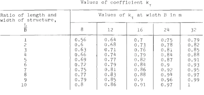
(3) effect of dimensions and plan form of building or structure is ac-counted for by coefficient k (Table VII) which represents the ratio of actual
T
thawing depths in unidimensional (h ) and multidimensional (h 1) problems:
c c
(24)
(4)
progress of thawing with time is accounted for;(5)
regulation of depth and rate of thawing is done by varying the ther-mal resistance of the enclosure calculated in the form of equivalent layer0np
(formula (29);(6) when necessary, the above is also achieved by creating additional heat loss at the ground surface beneath the floor of the structure by cold air ventilation.
63. The depth of thaw of frozen soil beneath the centre of a building or structure is determined from the equation (by measuring from the level of the floor):
Table VII
Values of coefficient k
T
Ratio of length and Values of k at width B in m
width of structure, T L
-8
16
24
B12
32
10.56
0.64
0.7
0:75
0.79
2
0.6
0.68
0.73
0.78
0.82
3
0.63
0.71
0.76
0.81
0.85
4
0.66
0.74
0·79
0.84
0.88
5
0.69
0.77
0.82
0.87
0.91
6
0.72
0·79
0.84
0.9
0.93
7
0.75
0.81
0.86
0.92
0.95
8
0.77
0.83
0.88
0.9
110.97
9
0.79
0.85
0.9
0.96
0.99
10
0.8
0.86
o.
en
0.97
1
64.
The depth of seasonal thawing of soil which is not beneath a build-ing or structure may be also determined from equation(25)
by eliminating the coefficient k which accounts for the effect of the thermal regime of aT
building or structure in relation to their dimensions.
65.
The time required for thawing soil to the given depth h beneathc the centre of a building is determined from the equation:
(:: +201l)rq-C..
HQNYヲッK。NUヲセIK
+
a.SCT·tn ] ·( 26)
The same beneath the edge of the building and to depth セサZ
'C
h = _ _h_"_ _
HセK
2 On) [q - C..(1.9/0+
0.5/.,)+
" 2k,AT!n K c ktKc
+0.5CTtnJ·
(26a)
66.
In practice the final estimated depth of thaw is defined by timeT
S' when its increment per year at e =
0.1
will be: for buildings andstruc-tures of category I (with respect to rigidity) -
0.2
m, category II -0.4
m,and category III -
0.5
m; at e =0.03, 0.6, 1.2
and1.5
m. respectively. The1:
maximum estimated period of thawing must not exceed the estimated period of amortization of structure.
67.
The depth of thaw beneath the edge of a structure may be determined tentatively from the equation:where K is the coefficient of proportionality. c
68.
The rate of thawing of frozen soils beneath a structure is takento be equal to the depth of thaw in one year of operation and is determined from the formula:
h - h
(lc
=
•
n+I •nm/year.tn+l - til
(28)
To determine the maximum rate of thawing beneath a foundation base, it is essential to know time Tn' when the thawing curve will reach the founda-tion base, i.e. when hKn = hm .4,n It is then necessary to calculate the depth of thaw in the following year of operation h
Kn
+
l ' i.e. in time Tn+
l ' The difference of these values, with reference to one year, will be equal to the maximum rate of thawing beneath the foundation. It is determined fromh¢.n+,-hcl>n
1Ic.'''I<C = t _ t'
n+1 II
(28a)
69.
When the difference in settlement of the foundations of buildings and structures exceeds permissible limits, it is essential to reduce the depth and rate of thawing of the frozen soils by changing the thermal effect of the foundation soils on the structure by selecting a suitable thickness of thermal insulation on enclosures or by applying ventilation with cold air.70.
The corrected thickness of thermal insulation 0np.c and 0np.K re-sistance of insulationR
n p required for reducing the depth of thaw of soilbeneath the centre and the edge of a structure to a given maximum value h c. n p with allowances for dimensions and plan form of buildings are determined from the formulae:
beneath the edge
Cnp.c" I I 2/h /d /k 1 Rnp= _ _ - - - - m r eg ca.
Ar a o all
Design of Natural Ventilation of Enclosing Elements in the Foundation of BUildings and Structures
(29a)
(30 )
71. The cooling installations used in heat-emitting buildings and struc-tures represent a system of air passages with shafts for inflow and outflow
parts of bottom and side enclosures of the structure. As a rule, the air passages operate on the principle of natural ventilation due to thermal and wind pressure.
72.
Cross-sections and heights of inflow and outflow air shafts, number and type of baffles, and mode of operation are determined by the thermal equilibrium of a building or structure and the foundation soil, as shown by the following equation:EQ
=
Q.+
Q2+
Q3= 0kcal/hr, ( 31)where Q} heat flow through structural enclosure in kcal/hr;
Q2 - heat flow through walls of ventilation conduits and into the
ground in kcal/hr;
Q3 - heat flow through the cooling system in kcal/hr.
Heat flow Q} is found from the formula:
where EK - general coefficient of heat transfer of enclosure in kcal/m2 / h r / d e g ;
F
n
area of external bottom and side enclosure of structure in m2 ;t
n -
air temperature within the enclosure;t H - temperature of external surface of enclosure. Heat flow Q2 is determined from the formula:
AT....
Q2=
±
Fa - -tK kcal/hr,. (33)hc,f
where
A
T,M-
coefficient of thermal conductivity of thawed and frozen soilin
m;
in kcal/m/hr/deg;
depth of thaw or freezing of soil beneath the enclosure h
c,f
t H - air temperature in ventilation セッョ、オゥエウ in the walls of enclo-sure beneath the structure; it is found from formulae used in heat engineering and is expressed in degrees.
Explanatory notes. 1. Signs ± indicate thawing and freezing of soil, respectively.
2. When estimating the depth of winter freezing h
f, T is taken to be equal to the number of hours within the period of freezing; Q2 should be posi-tive.
The heat flow through the ventilation system Q3' which is due to a dif-ference in the temperatures of the outside air (t
E o B ) and the air in the con-duits (t K) is found from the equation:
"here V
H
r»
U vp
volume of air passing through the ventilation system in m3 / h r ; vOlumetric heat capacity of air at given constant pressure in
kc a Lzrn ".
VH - determined from the formula:
v
= F It11
2g he(f" - 15) 3600J( "r-.' 1. '
( 35 )
where F
H - area of cross-section of ventilation openings in m
2 ;
hE - distance between inflow and outflow shafts and the neutral zone i.n m;
YII B - specific gravity of outside and inside air in kg/m3 ;
,
g - acceleration due to gravity in m/sec2 ;
3600 - conversion factor (for converting seconds into hours);
WB - coefficient of consumption which depends on the form and aero-dynamic properties of air passages and ventilation openings, and is determined from the formula:
C3 6)
where iセ - sum of local resistances in the outflow air shaft which is
de-termined according to rules of heat engineering;
n
£ - loss through friction in the outflow shaft;d
n -
coefficient of friction taken to be 0.2; 1 - length of outflow shaft in m;d - diameter of the above in m.
73.
The heat flow through the cooling ventilation systems with bafflesresulting from thermal and wind pressure HqSセI is found from the formula:
( 37)
where vセ - efficiency of baffle in m3 / h r , determined from the formula:
wher-e n - number of baffles;
F g - area of the outlet of the baffle in m2;
uセ velocity of air in the outlet of the baffle in m/sec;
I
2 2ghR(1" -1.)kセuNKMMMMM
U.I
-1
- • 10Ie..
+
1:;/+
セd
where kセ - coefficient of streamlining of baffle (taken from Table VIII); DB - wind velocity in m/sec determined from handbooks of the
Hydro-Meteorological Service;
セ - resistance of baffle to wind pressure (from Table VIII);
,I\
]セN sum of local resistances in the outflow air shaft where the air
1-travels before entering the outlet of the baffle; it is determined from formulae used in heat engineering; the coefficient of resist-ance of the baffle itself セ is given in Table VIII.
c Table VIII
Aerodynamic characteristics of baffles
Type of baffle kセ セセ セ」
TsAGI, cylindrical oNセ 1.2 0.61
TsAGI, rectangular 0.28 1.6 0.67
"Zvezdochka" oNセャ 1. 88 1
Grigorovich system 0.33 1.セ セ 1.oセ
WセN It is recommended to design the cooling ventilation conduits
be-neath a building or structure according to the following equations: Ventilation Due to Thermal Pressure
For the period of positive temperature of the outside air:
AT
QI - Q2 = EKFn(tn - tH) - Fn
h .
tH•• """ O.e
For the period of negative temperatures of the outside air:
(セ 1)
Ventilation Due to Thermal and Wind Pressure
For the period of positive temperatures of the outside air use equa-tion HセoIN
For the period of negative temperatures of the outside air use the follow-ing equation:
Q.
+
Q2 - Q3A=
EKFn(tn - tH )+
fョGセ
t,,-hI - V"C"p(tHo. - i.) 3600= O.
qSセ is found from equation (37).
in the fッオョ、。エゥッセ of Structures
75.
Artificial ventilation should be applied when it is not possibleto depend on natural draft, i.e. when the bUilding or structure exceeds 20 m in width or when there is a basement, while thermal pressure is not adequate. In this case it is recommended to install ventilation conduits for the incom-ing air blown in by a fan and conduits for the outgoincom-ing air. The fan should be installed near the outflow conduit, since warmer out flowing air has a
lower moisture content which may corrode the ventilator. The fan accumulates
cold air in the cold season and retards the thawing process in the warm sea-son.
76.
Ventilation conduits should consist of assembled concrete sections, since this speeds up and mechanizes the work.77.
In the design of fans for service in the condUits, the difference in temperatures of incoming and out flowing air should be estimated by consid-ering the average temperature of the outside air and the air within thestruc-tures, as well as the effect of the thermal insulation of enclosures. This
difference should not be less than lODe.
78.
The required power of a fan is determined by estimating heat losses through the floor, and, if there is a basement, through the walls of the build-ing or structure as well.There are three types of centrifugal fans:
(a) low pressure fans - up to 100 mm water column; (b) medium pressure fans - up to 300 mm water column; (c) high pressure fans - up to 1500 mm water column.
79.
It is recommended to use low pressure centrifugal fans inventila-tion systems of public and industrial buildings. Medium pressure fans are used, as a rule, for ventilation of industrial bUildings with ventilation ca-nals of considerable length and resistance of more than 100 mm water column.
High pressure fans should be used for ventilation of industrial build-ings of considerable size with underground basement and ventilation conduits of considerable length and resistance of network exceeding 300 mm water col-umn.
The efficiency of fans may vary between 1000 and 30,000 m3 / h r and more,
depending on their type, number and rotations per minute.
80. The power of the electric motor is determined from the formula:
QrH KH
N = - - - - K B T