HAL Id: cea-02338562
https://hal-cea.archives-ouvertes.fr/cea-02338562
Submitted on 24 Feb 2020
HAL is a multi-disciplinary open access
archive for the deposit and dissemination of sci-entific research documents, whether they are pub-lished or not. The documents may come from teaching and research institutions in France or abroad, or from public or private research centers.
L’archive ouverte pluridisciplinaire HAL, est destinée au dépôt et à la diffusion de documents scientifiques de niveau recherche, publiés ou non, émanant des établissements d’enseignement et de recherche français ou étrangers, des laboratoires publics ou privés.
Facility Preventing Initial Interfacial Crusts
V. Bouyer, A. Denoix, C. Journeau, D. Molina, P. Piluso, J.-F. Haquet, J.
Foit, B. Fluhrer, A. Miassoedov
To cite this version:
V. Bouyer, A. Denoix, C. Journeau, D. Molina, P. Piluso, et al.. Molten Core Concrete Interaction Test in VULCANO Facility Preventing Initial Interfacial Crusts. NUTHOS12 - 12th International Topical Meeting on Nuclear Reactor Thermal-Hydraulics, Operation and Safety, Oct 2018, Qingdao, China. �cea-02338562�
Abstract No: 344 Oral presentation or Poster □ Paper No.:
Molten Core Concrete Interaction Test in VULCANO Facility Preventing
Initial Interfacial Crusts
Bouyer V, Denoix A, Journeau C, Molina D, Piluso P
CEA
DEN, Cadarache, DTN, SMTA, LEAG, 13108 St Paul lez Durance, France
[email protected]; [email protected]; [email protected]; [email protected];
Haquet JF
CEA
DEN, Cadarache, DTN, SMTA, LMAG, 13108 St Paul lez Durance, France
Foit J, Fluhrer B, Miassoedov A
Karlsruhe Institute of Technology
IKET, Hermann-von-Helmholtz-Platz 1, 76344 Eggenstein-Leopoldshafen,Germany
[email protected]; [email protected]; [email protected]
ABSTRACT
In the frame of the Severe Accident Facilities for European Safety Targets (SAFEST) project, Karlsruhe Institute of Technology (KIT) and the Society for installation and Reactor Safety (GRS) have proposed to realize a Molten Corium Concrete Interaction (MCCI) test in the VULCANO facility located at the PLINIUS experimental platform, CEA Cadarache. The MCCI test, named VBES-U5, was carried out on July 20th, 2017. 50kg of thermite has reacted to melt a prototypic corium in a siliceous concrete test section, which was then heated by induction. The test section was 2D cylindrical with an inner diameter of 250 mm, an outer diameter of 500 mm, an inner height of 300 mm and outer height of 475 mm. MCCI was carried out for 40 min which conducted to an axial ablation of 10 mm and a radial ablation of 60 mm. Great care has been taken to prevent initial crust formation (corium composition such that initial contact temperature is above solidus, high power during the first minutes). Nevertheless, a pronounced radial ablation has been observed for this siliceous concrete, similarly to previous VULCANO tests in which initial crust formation was likely to occur.
KEYWORDS
SEVERE ACCIDENTS – MCCI – CORIUM – CONCRETE – INITIAL CONDITIONS
1. INTRODUCTION
Molten Core Concrete Interaction (MCCI) occurs in nuclear reactor severe accident scenarios in which the reactor vessel fails and corium – the liquid mixture generated by the melting of fuel assembly and its mixing with nearby structural materials – is poured in the reactor pit and interacts with the concrete floor and walls [1]. MCCI is one of the high priority topics in severe accident experimental research [2]. One of the issues is to understand the different ablation behaviors that have been observed depending on the nature of the concrete [1].
Several phenomena have been considered as possible cause of the differences between siliceous and limestone-rich concretes with respect to MCCI ablation [3]. Recent analysis of the MOCKA
Abstract No: 344 Oral presentation or Poster □ Paper No.:
experiments [4] has put emphasis of the potential role of the initial crust formed at the corium concrete interface. Also, in the CCI experiments [5] at ANL, the contact temperature at the melt/concrete interface was below the solidus temperature of the corium mixture. The initial crusts, which must have formed at the oxide/concrete interface for all these tests are moreover not appreciably heated by the electrical heating system of these tests. A local crust failure in all tests with siliceous concrete can then cause the observed non-isotropic ablation shapes. On the contrary, the high gas release rates from the decomposing Limestone-Common Sand (LCS) concrete can help to destabilize these initial crusts as observed in the quite isotropic ablation of CCI-2 test [6].
The VULCANO VB-ES-U5 experiment has been proposed to prevent initial crust formation at the start of MCCI with siliceous concrete and to observe the ablation shape. This proposal has been selected by SAFEST international selection panel and has been carried out at CEA Cadarache on July 20th, 2017.
2. DESCRIPTION OF FACILITY
2.1. General description
VULCANO is a facility where several kinds of corium tests have been already performed using prototypic corium i.e. with depleted uranium dioxide [10], among them, spreading [7], MCCI [8] and coolability [9] tests. Several melting techniques have been developed and used to synthetize corium at high temperature (above liquidus temperatures) such as plasma arc rotating furnace [11], thermite reaction [12] and induction heating [13] in order to have controlled initial conditions for the understanding and modelling of the studied phenomena. Decay heat in corium can be simulated using induction heating, to represent real conditions of reactor severe accident.
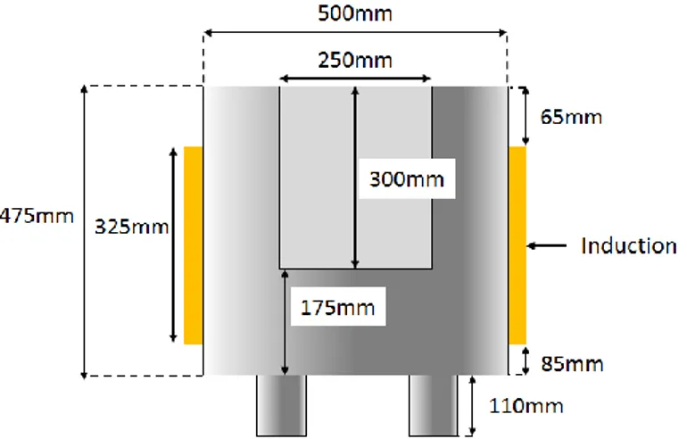
For VBES-U5 MCCI test, a dedicated concrete test section has been designed. This test section has a 2D axisymmetric configuration (see Fig. 1) so the inner crucible is cylindrical with a diameter of 250 mm and a height of 300 mm. The maximum concrete thickness that can be ablated radially and axially is about 100 mm. The crucible is filled with 50 kg of corium so that the thickness of the formed corium pool is about 120-130 mm.
Thermite reaction [12, 14] is used to obtain corium. Taking into account the initial thermite mixture density compared to that of the final liquid state corium, a zirconia tube is disposed on top of the test section in order to contain initial thermite powders. At the top of the thermite powder, in order to ignite the reaction, a Pyrofuze® wire is placed below the powders mixture surface.
An induction generator is used to provide sustained heating of the corium.
2.2. Induction heating
The whole upper part of the concrete test section is surrounded by the inductor, made of two cylindrical coils (Fig. 2). The induction system is composed with:
- a CELES HF generator of maximum power 400 kW, frequency between 70 and 300 kHz;
- a CELES impedance matching box,
- an induction line connecting the matching box to the inductor,
- cooling systems (with flowmeters and thermocouples for thermal balance), - a Faraday cage around the experimental device (see Fig. 3).
The high frequency generator and the matching box are located at the ground floor of PLINIUS platform, underneath VULCANO room. The induction current in the inductor is measured with a Rogowski probe.
Abstract No: 344 Oral presentation or Poster □ Paper No.:
Fig. 1 Sketch of tVBES-U5 concrete test section with induction coils around.
Fig. 2 VBES-U5 inductor coils.
Fig. 3 VBES-U5 experimental set up in VULCANO. Faraday cage
Arc plasma furnace used by the past
Test section and induction coil
Abstract No: 344 Oral presentation or Poster □ Paper No.:
3. TEST DEFINITION
3.1. Concrete
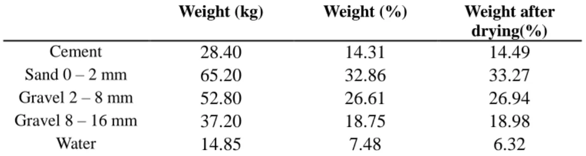
Concrete type is siliceous. Sands, cement and gravel have been provided by KIT. Mass proportions for manufacturing 200 kg of concrete are given in Table 1. We measured the loss of water on concrete samples until the day before the test and determined a loss of about 1.24 weight % of the total mass of the sample. At the start of the experiment, only 6.3 wt% of water are considered to be present in the dried concrete.
Table 1 : Mass proportion of prepared concrete components. Weight (kg) Weight (%) Weight after
drying(%) Cement
28.40
14.31
14.49
Sand 0 – 2 mm65.20
32.86
33.27
Gravel 2 – 8 mm52.80
26.61
26.94
Gravel 8 – 16 mm37.20
18.75
18.98
Water14.85
7.48
6.32
3.2. Corium thermiteThe corium contains both oxide and metal (UO2/ZrO2/metal/concrete: 61.3% / 25.2% / 9.9% / 3.6%). It is obtained by thermite reaction. The thermite composition is shown in Table 2. We prepared 50 kg of thermite in 25 batches of 2 kg. Each batch has the same composition and is prepared in a glove box under a controlled atmosphere with concentrations of O2 and H2O below 100 ppm. The whole thermite is prepared one week before the day of the test and is stored in the glove box until then. For 50kg of thermite of the given composition the reaction temperature is 2366 °C (calculated with the Gibbs Energy Minimizer Gemini-2 [15] and the NUCLEA-14 thermodynamic database [16]).
Table 2 : Composition of the thermite raw powders of VBES-U5 test Reactants U3O8 Zr CrO3 Fe2O3 Si Mg Al CaO
% (wt) 63.76 18.65 3.80 11.30 0.72 0.30 0.10 1.39
Mass (kg) 31.88 9.32 1.90 5.65 0.36 0.15 0.05 0.69
Corium composition after the thermite reaction is shown in Table 3.
Table 3 : Composition of the corium of VBES-U5 test
Components UO2 ZrO2 Cr Fe SiO2 MgO Al2O3 CaO
% (wt) 61.33 25.19 1.98 7.90 1.53 0.50 0.18 1.39
Mass (kg) 30.67 12.59 0.99 3.95 0.77 0.25 0.09 0.69
3.3. Instrumentation
VULCANO experimental devices are instrumented [17] in order to monitor the corium synthesis at high temperature and the induced power in the pool as well as to follow the MCCI phenomena (temperature increase, ablation, …).
Test section is equipped with 129 type K (chromel-alumel) thermocouples and 6 type C (tungsten-rhenium) thermocouples that are tied or bonded to a Nylon wire in order to be positioned before
Abstract No: 344 Oral presentation or Poster □ Paper No.:
concrete casting. The sensors are located on 6 azimuths located every 60° at several heights and radiuses: 3 azimuths are dedicated to measurement (temperature increase, ablation…) and 3 azimuths are dedicated to safety in order to avoid melt spreading outside of the test section. Their main role is to track the concrete ablation front, identified as being the thermocouples failure. The signals also give information on the heating of the concrete. 6 type C thermocouples have been used to measure temperature in the corium pool with either ceramic protection sheath (material A: external diameter 14.5 mm and material B – ZrO2 based: external diameter 9 mm) or not (in this case, captor is only sheathed with molybdenum).
To monitor the surface temperatures, 4 bichromatic optical pyrometers were used. In this test conditions, temperature measurement uncertainties are of the order of 50 K, with emissivity at the pyrometer two wavelengths as the major source of uncertainty. The melting of corium and the progress of corium–concrete interaction are monitored by 4 cameras.
3.4. Initial conditions
3.4.1. Melt initial temperature
In order to avoid the formation of initial crust at the beginning of MCCI with the siliceous concrete, we verified that the initial contact temperature between corium and concrete would be above the solidification temperature of corium.
An initial contact temperature can be estimated for the corium/concrete interface assuming convection effect can be neglected at the initial instants before bubbling or natural convection have started (the start of convection should increase the heat flux on the corium side and shift the contact temperature towards the corium temperature). Using conservation of heat flux between to semi-infinite walls (corium and concrete with initial temperatures and such as
), equation (1) gives such as:
(1)
With thermal conductivity in W/m/K, density (kg/m3) and specific heat (J/kg/K).
The corium composition and initial temperature have been selected so that . We can determine the corium temperature such as and compare the obtained value to the initial temperature of the corium melt corresponding to thermite reaction temperature at thermodynamic equilibrium. Data are given in Table 4. Temperature of corium corresponding to thermite reaction temperature at thermodynamic equilibrium (2366°C) is 800°C above . Thus, using corium thermite composition defined in section 3.2, there are sufficient margin for non-adiabatic heat losses to prevent the formation of a solid crust at the beginning of the experiment.
Table 4 : VBES-U5 initial characteristics of the corium melt
Data °C
Solidus temperature of corium 1197
Minimum corium temperature ensuring contact temperature above solidus .
1564 Adiabatic reaction temperature of corium 2366
3.4.2. Induction power input
Abstract No: 344 Oral presentation or Poster □ Paper No.:
200 kW/m2 corresponding to an injected power of 40 kW in the corium pool. As an additional caution in order to prevent the possibility for crust early formation, it has been chosen to inject first 200 kW to remelt crust (presumably in semi-solid state) that would have formed at the initial contact. This short period of high heat flux could also be considered as a simulation of the important heat generation that exothermal oxidation of zirconium by concrete volatiles (steam, carbon dioxide) generates. As soon as 2 cm of concrete ablation is obtained, power is decreased from 200 kW to 40 kW and MCCI proceeds with lower heat fluxes until the ablation limit is reached.
4. TEST DESCRIPTION
4.1. Test sequence
The test begins with the ignition of the thermite reaction by the melting of the Pyrofuze® wire leading to the melting of 50 kg of corium. About 1 min and a half after ignition, the melt is heated with induction at the average power of 200 kW to prevent any initial crust formation. Axial and radial ablation is observed. Once about 2 cm of radial ablation is reached, after about 2 minutes of heating, inductive power is stopped during 30 s in order to verify that measurements are not disturbed by induction heating. Inductive heating is then switched on again with an input power of 40 kW. Heating has been maintained during nearly 40 min until a safety thermocouple at the rims of the test section triggers alarm.
4.2. Injected power
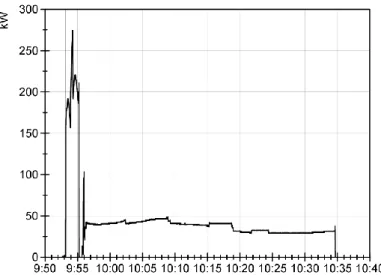
Fig. 4 shows the injected power curve obtained during the test. At the beginning of the test, during 2 minutes corresponding to the ablation of the first 2 centimeters, the average injected power is 189 kW. The large variation with maximum and minimum values at respectively 273 kW and 160 kW is explained by the monitoring of induction generator on tension mode. Then, tension is lowered and about a 37 kW average power is injected in the corium pool during nearly 40 min: during the first 20 min, the power is about 41.6 kW and then slightly decreased to 30.4 kW. This power input curve is in accordance with test objectives.
Fig. 4 VBES-U5 injected power curve during MCCI process.
4.3. Pool temperature
Temperature measurements in the pool allow to identify the melting of the corium: TC 150 and 149 characterize the combustion front progression in the thermite mixture. Response of thermocouples protected with ceramic is delayed due to thermal inertia. TC 137 with a ceramic sheath enables to
Abstract No: 344 Oral presentation or Poster □ Paper No.:
follow the temperature of the pool up to a maximum measurement at 2095°C which is well above . From the time injected power in the pool is constant at about 37 kW, temperature is almost constant at 1666±8°C during at least 20 min until the destruction of the sensor.
Fig. 5 VBES-U5 temperature in the corium pool measured with type C thermocouples. TC 137 material A at 50 mm; TC 141 material B and TC 139 at 20 mm; TC 149 and TC 150 with no sheath at
80 and 100 mm (distances are given from the bottom of the crucible).
4.3. Concrete ablation
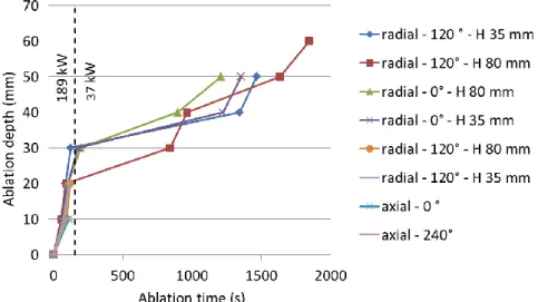
The analysis of thermocouples signals in the concrete gives information on ablation times and radial and axial depths. Fig. 6 shows the progression of ablation front at each azimuth and ablation velocities are given in Table 5. Apart from azimuth 240°, radial ablation depths as a function of time are the same for azimuth 0° and 120° with ablation velocities for the high power and low power steps at respectively 69 cm/h and 6 cm/h. On azimuth 120°, ablation is the same during the high power phase but stopped at 2 cm. This stop could be linked to the presence in the concrete of 4 type C thermocouples sheathed with molybdenum inducing a greater thermal conductivity of the captors compared to type K thermocouples. On the axial direction, ablation progress is only visible during the high power step and is almost twice slower than radially at about 35 cm/h.
Fig. 6 VBES-U5 concrete ablation. H in caption corresponds to the height of radial thermocouples from the bottom of the crucible.
Abstract No: 344 Oral presentation or Poster □ Paper No.:
Table 5 : VBES-U5 ablation velocities
Injected Power (kW) 189 37
Radial ablation velocity (cm/h) 68.7±11 5.9±0.3 Axial ablation velocity (cm/h) 35.2±5.8 -
4.3. Posttest dismounting and ablation profile
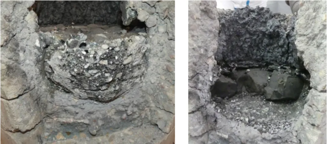
Removal of concrete in contact with corium revealed the corium pool (Fig. 7) and enables to make the following observations on the pool structure:
- there is a continuous crust at the upper level of the corium pool, with a thickness of about 15 mm. This crust is composed of corium and pieces of concrete aggregates with large voids (around 20 mm diameter) between the crust and the corium below;
- corium pool is about 100 mm height. There is almost no porosity inside the corium pool (just a few bubbles) and it seems homogenous;
- a continuous crust exists at the lower level and side in contact with concrete. This crust has less corium and more concrete aggregates than the upper one and also less bubbles;
- no metallic pool has been found during the dismantling. It is assumed that metallic phase has been (almost) totally oxidized during this test. Moreover, with the presence of oxygen during the thermite reaction, it is considered that post-combustion [14] may have occurred, conducting to oxidation of Cr and Fe forming Cr2O3 and Fe2O3.
- radial and axial ablations are respectively about 60 mm and 10 mm, which is consistent with the thermocouples measurements.
Fig. 7 VBES-U5 corium pool.
5. SYNTHESIS AND CONCLUSIONS
During VBES-U5 test, 50kg of thermite has reacted to melt a prototypic corium in a test section made of siliceous concrete. The corium was then heated by induction. The test section was 2D cylindrical with an inner diameter of 250 mm. MCCI was performed for 40 min which conducted to an axial ablation of 10 mm and a radial ablation of 60 mm.
Great care has been taken to prevent initial crust formation (corium composition such that initial contact temperature is above solidus, high power during the first minutes). Nevertheless, a pronounced radial ablation has been observed for this siliceous concrete, similarly to previous VULCANO tests [8] in which initial crust formation was likely to occur. Investigation must continue to find the consistent explanation of the observed differences of ablation patterns between siliceous and limestone concretes.
Abstract No: 344 Oral presentation or Poster □ Paper No.:
ACKNOWLEDGMENTS
The SAFEST project is funded by the EURATOM 7th Framework Programme under grant agreement n° 604771.
The work and efforts of the whole PLINIUS experimental team are gratefully acknowledged.
REFERENCES
1. J.M. Bonnet, F. Robledo, M.T. Farmer, M. Cranga, C. Spengler, D. Vola, S. Basu, K. Atkhen, A.
Fargette, M. Fischer, J. Foit, A. Hotta, C. Journeau, C. Marchetto, A. Morita, E. Moiseenko, F. Polidoro and Q. Zhou, State-of-the-Art Report on Molten Corium Concrete Interaction and
Ex-Vessel Molten Core Coolability, OECD Nuclear Energy Agency Report NEA/CSNI/R(2016)15
(2017).
2. C. Journeau, V. Bouyer, N. Cassiaut-Louis, P. Fouquart, P. Piluso, G. Ducros, S. Gossé, C. Guéneau, A. Quaini, B. Fluhrer, A. Miassoedov, J. Stuckert, M. Steinbrueck, S. Bechta, P. Kudinov, W. Ma, B.R. Sehgal, Z. Hozer, A. Guba, D. Manara, D. Bottomley, M. Fischer, G. Langrock, H. Schmidt, M. Kiselova, J. Zdarek, SAFEST Roadmap for Corium Experimental research in Europe,
ASCE-ASME Journal of Risk and Uncertainty in Engineering Systems Part B: Mechanical Engineering,4(3) 030901 (2017).
3. C. Journeau, J.F. Haquet, P. Piluso, J.M. Bonnet, “Differences between silica and limestone concretes that may affect their interaction with corium”, Proc. Int Conf. Advances nucl. Power
Plants ICAPP08, Anaheim, Ca. (2008).
4. J.J. Foit, M. Fischer, C. Journeau, G. Langrock, “Experiments on MCCI with oxide and steel”,
Ann. Nucl. Energ. 74, pp. 100-109 (2014).
5. M.T. Farmer, C. Gerardi, N. Bremer, S. Basu, “Key findings and remaining questions in the area of Molten Core Concrete Interaction and Debris Coolability”, Nucl. Technol. 196 (3), pp. 461-474 (2016).
6. M.T. Farmer, S. Lomperski, S. Basu, “The results of the CCI-2 reactor materialexperiment investigating 2D core concrete interaction and core debris coolability”, Proc. 11th International
topical meeting on nuclear reactor thermal hydraulics (NURETH 11), Avignon, France (2005).
7. C. Journeau, E. Boccaccio, C. Brayer, G. Cognet, J.F. Haquet, C. Jégou, P. Piluso and J. Monerris, “Ex-vessel corium spreading: results from the VULCANO spreading tests”, Nucl.Eng. Des.,
223(1), pp. 75-102 (2003).
8. C. Journeau, P. Piluso, P. Correggio, L. Ferry, G. Fritz, J.F. Haquet, J. Monerris, J.M. Ruggieri, M. Sanchez-Brusset and C. Parga, “Contribution of the VULCANO experimental program to the understanding of MCCI phenomena”, Nucl. Eng. Technol., 44(3), pp. 261-272 (2012).
9. C. Journeau and H. Alsmeyer, Validation of the COMET Bottom-Flooding Core-Catcher with Prototypic corium, Proc. Int. Congr. Advances nuclear Power plants (ICAPP06), Reno, NV, June 4-6 (2006).
10. V. Bouyer, N. Cassiaut-Louis, P. Fouquart, P. Piluso, “Plinius Prototypic Corium Experimental Platform: Major Results and Future Works”, Proc. 16th International topical meeting on nuclear
reactor thermal hydraulics (NURETH 16), Chicago, USA, August 30 – Sept 4 (2015).
11. C. Jégou et al., “Plasma transferred arc rotary furnace for corium melting”, J. High Temp. Mater.
Proc., 1, pp. 409-420 (1998).
12. P. Piluso, K. Mwamba and C. Journeau, “Uranothermic Reaction as an Efficient SHS Process to Synthesize Severe Accident Nuclear Materials”, Intern. J. Self-Propagating High-Temperature
Synthesis, 18, 4, pp. 241–251 (2009).
13. C. Journeau, J. Monerris, B. Tormos, L. Brissonneau, E. Excoffier, V. Testud, C. Chagnot, D. Roulet, “Fabricating Fukushima Daiichi in-vessel and ex-vessel fuel debris simulants for the development and qualification of laser cutting technique”, Proc. 8th European Review Meeting on Severe Accident Research (ERMSAR), Warsaw, Poland, May 16-18 (2017).
14. W. Weiser, “Experimental and theoritical comparison of a systematic variety of thermite compositions”, Proceedings of 46th International Annual Conference of the Fraunhofer ICT, Karlsruhe, Germany, June 23 - 26, 2015, 46, pp.24.1-24.14 (2015).
Abstract No: 344 Oral presentation or Poster □ Paper No.:
15. B. Cheynet, P.Y. Chevalier and E. Fischer, “Thermosuite”, Calphad, 26(2), pp. 167-174 (2002). 16. S. Bakardjieva, M. Barrachin, S. Bechta, D. Bottomley, L. Brissonneau, B. Cheynet, E. Fischer, C.
Journeau, M. Kiselova, L. Mezentseva, P. Piluso and T. Wiss, “Improvement of the European thermodynamic database NUCLEA”, Progress in Nuclear Energy, 52, pp. 84–96(2010).
17. V. Bouyer, P. Piluso, C. Journeau, C. Parga, N. Cassiaut-Louis, P ; Fouquart, “High temperature measurements in severe accident experiments on the PLINIUS platform”, Proc. 3rd Int. Conf. Advancements in Nuclear Instrumentation Meas. Methods & Applications (ANIMMA), Marseille,