HAL Id: cea-02489491
https://hal-cea.archives-ouvertes.fr/cea-02489491
Submitted on 24 Feb 2020HAL is a multi-disciplinary open access archive for the deposit and dissemination of sci-entific research documents, whether they are pub-lished or not. The documents may come from teaching and research institutions in France or abroad, or from public or private research centers.
L’archive ouverte pluridisciplinaire HAL, est destinée au dépôt et à la diffusion de documents scientifiques de niveau recherche, publiés ou non, émanant des établissements d’enseignement et de recherche français ou étrangers, des laboratoires publics ou privés.
Reproducing the cooling towers cracks on laboratory
specimens for corrosion induced by carbonation studies
R.M. Ghantous, V. l’Hostis, S. Poyet, Raoul François, N.C. Tran
To cite this version:
R.M. Ghantous, V. l’Hostis, S. Poyet, Raoul François, N.C. Tran. Reproducing the cooling towers cracks on laboratory specimens for corrosion induced by carbonation studies. CIGOS-PARIS 2015 - Conférence internationale de géotechnique, des ouvrages et structures, May 2015, Paris, France. �cea-02489491�
1
Reproducing the cooling towers cracks on laboratory specimens for
corrosion induced by carbonation studies
R.M. Ghantous1
CEA, DEN, DPC, SECR, Laboratoire d’Etude du comportement des Bétons et des Argiles, F-91191 Gif sur Yvette cedex, France ([email protected])
V. L’Hostis1
CEA, DEN, DPC, SECR, Laboratoire d’Etude du comportement des Bétons et des Argiles, F-91191 Gif sur Yvette cedex, France ([email protected])
S. Poyet1
CEA, DEN, DPC, SECR, Laboratoire d’Etude du comportement des Bétons et des Argiles, F-91191 Gif sur Yvette cedex, France ([email protected])
R. François2
Laboratoire Matériaux et Durabilité des Constructions, 135 avenue de Rangueil, F-31077 Toulouse cedex 4, France (raoul.franç[email protected])
N.C. Tran3
EDF, R&D, MMC, avenue des Renardières, Ecuelles F-77818 Moret-sur-Loing cedex, France ([email protected])
Abstract:
This paper presents an experimental program allowing determining the effect of cracks and their orientations on initiation and propagation of reinforcement steel corrosion due to carbonation. The influence of different environmental conditions will be tested in order to propose an operational model allowing the evaluation of the kinetic of corrosion of the reinforcement steel in cooling towers of nuclear power plants (NPP). The cracking mode that generates cracks which are representative of those appearing on the cooling towers is a three-point bending test performed on prismatic specimens of 70×70×280 mm3 size with 6 mm steel bars. The length of damaged steel / mortar interface, which appears following a three-point bending test, is then quantified. This length could be determining in the initiation and the propagation of corrosion. Results show that this length is dependent on the residual crack opening and that the length of damaged interface in its lower part is larger than that on the upper part due to the casting direction. After cracking, the specimens will be exposed to carbon dioxide to ensure carbonation of the steel bar localized at the bottom of the crack and the mortar/steel interface, damaged by the load applied during the three-point bending test. After carbonation of the interface, specimens will be submitted to corrosion in different environmental conditions whose effect on the kinetics of corrosion will be determined.
2
Main subthemes (Tick one item):
◾ Advances in Modeling of Structures (AMS) ◾ Materials for Construction (MFC)
◾ Innovative Design and Methods in Construction (IDM) ◾ Geotechnics for Environment and Energy (GEE)
1. Introduction
The corrosion of steel is the main pathology affecting reinforced concrete structures and therefore it is a determining factor for their durability. To properly determine the durability of a construction, it is necessary to fully understand the phenomena that threaten it.
In this study, we are interested in the durability of cooling towers of EDF NPP; some of them have a state of more or less advanced damage characterized by the presence of cracks [1]. The latter may be due to physical aspects (restrained shrinkage, wetting/drying cycles and gradients of relative humidity and temperature through shell’s thickness) and mechanical aspects (wind loading and differential settlements).
It is well known that cracks facilitate the diffusion of atmospheric carbon dioxide in concrete and thus enhance carbonation in the cracked zone. This carbonation induces steel corrosion which could cause the development of new cracks in the structure thus threatening its durability.
[2] and [3] have discussed the development of corrosion due to carbonation depending on the cracks spatial density and their openings. Nevertheless, the propagation of corrosion in pre-cracked concrete is still a subject in debate. There have also been studies on the possibility of self-healing of these cracks (in saturated conditions) induced by ongoing hydration and carbonation ([4]–[6]). However, the effect of crack opening on the carbonation that induces corrosion on the steel-concrete interface has not been widely studied. Nevertheless, following the study of [7] on the carbonation of hardened-steel ring pre-cracked through an expansive core test; it was found that the crack opening does not affect the carbonation of the steel/concrete interface that intercepts the crack, but it affects the diffusion of CO2 perpendicularly to the crack surfaces. This result is
consistent with the study of [8] which furthermore shows the existence of the “top bar” effect on the development of corrosion.
For a better control of cooling towers concrete damage evolution, it is interesting to apprehend the development of corrosion due to carbonation in cracked concrete. The main objectives of this project is to study the kinetics of corrosion in different environments (rain, wind, temperature ...) with different crack opening, in order to simulate the development of corrosion at steel/concrete interface intercepting the cracks over the entire NPP cooling tower’s circumference. Moreover, it is important to understand the effect of cracking, both in terms of corrosion initiation and propagation to propose a model illustrating the corrosion kinetic under these conditions.
This project’s developments will be implemented into numerical tools developed by EDF R&D aiming to evaluate the degradation of cooling towers in order to optimize the maintenance program to ensure their operating lifetime of 60 years.
This paper is organized as follows. First, the experimental method is introduced, the specimens dimensions and compositions are presented, then the cracking protocol is described and the different environmental conditions are chosen and interpreted. Suitable conclusions are deduced.
3 2. Experimental method
The main concern of this section is to present the different experimental conditions, from the specimen compositions and preparations till the corrosion analysis that enable to reproduce, as accurately as possible, the natural conditions that stand behind the corrosion in the cooling towers. 2.1. Materials
2.1.1. Cementitious materials
The materials prepared in the laboratory should be representative of those constituting the cooling towers. As informed by EDF, the concrete of the cooling towers was mostly made with water to cement ratio between 0.45 and 0.55 and a sand to cement ratio varying between the 2 and 2.2. The cement type mostly used is the CEM II/A-S. The latter cement is a blend of CEM I (70%) and slag (30%). Mixing slag with a CEM I cement doesn’t lead to the same properties of a CEM II. For this reason, most of the laboratory tests will be performed using a mortar mix based on the CEM I cement. And some experiments will be performed on a mortar mix based on the CEM II cement and on concrete based on the CEM I cement. The comparison of the kinetics of corrosion between these formulations allows deducing the effect of the slag on the kinetics of corrosion.
This study is performed on two scales: metric and centimetric.
In the metric scale, specimens are made of concrete with 1110 kg/m3 of aggregate (6/20), 750 kg/m3 of fine aggregate (natural sand 0/4), 350 kg/m3 of cement (CEM I 52.5), and 175 kg/m3 of water. The specimens in centimetric scale are made with a standardized mortar mix which uses three parts sand, two parts cement and one part water. A CEM I 52.5 cement and standardized sand CEN EN 196-1 will be used to design the mortar mixture.
The CEM II will be made manually by replacing 50% of CEM I by slag1. Moreover, to obtain comparative mixtures, all specimens will be performed using a 0.5 water to cement ratio and they will also have a common slump of 10 cm. For the CEM II mortar mixtures, a superplasticizer will be added to the mixture in order to reach the 10 cm slump.
2.1.2. Metallic materials and surface preparation The steel reinforcement bar used is the standardized Fe500.
The time needed for the corrosion to initiate is determining in this study. It is well known that the steel surface state in concrete affects the initiation of corrosion. That is why, the ideal is to have a uniform surface state throughout the steel bar.
Different steel surfaces are tested in the literature. It was determined that steel preparation by wire brushing leaves in place a cracked layer of calamine with a thickness less than 1 mm [9]. Defects are, therefore, points of weakness facilitating the initiation of micropile corrosion in the calamine layer. This can skew the experimental results. Indeed, if the defect in the calamine layer is localized at the crack tip of one specimen but not in the other, the comparison between them is not accurate. Thus, the preparation of steel bars using wire brushing is eliminated.
The preparation of steel surface by sandblasting is also tested in [9]. This method allows obtaining a uniform surface. However, the disadvantage of this method is the absence of the calamine layer leading to a lack in the representativity of the experimental test. On the other hand, according to the results of [9] and [10] cleaning steel surface by sandblasting slows the initiation of corrosion. These results are also supported by [11], [12]. Moreover, [13] indicates that sandblasting could inhibit the spread of corrosion. [12] indicates that the sandblasting changes the atomic composition of the steel bar. For all this reason, the sandblasting method is rejected in this study.
1
In fact, and in order to ensure that the slag ratio affects the kinetics of corrosion, this ratio is increased to 50%. If this latter is kept on 30%, the effect may not be visible.
4
Since all the preparation methods of steel surface are rejected, we choose in this study to use the steel as received without any action at its surface. Only the part of the steel bar reinforcement exposed directly to the atmosphere will be protected against corrosion.
2.2. Specimens characteristics and purposes
In the following, the preparation of the metric and centimetric specimens is presented. Their respective purposes and utilities are discussed.
2.2.1. Metric scale specimens
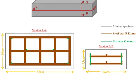
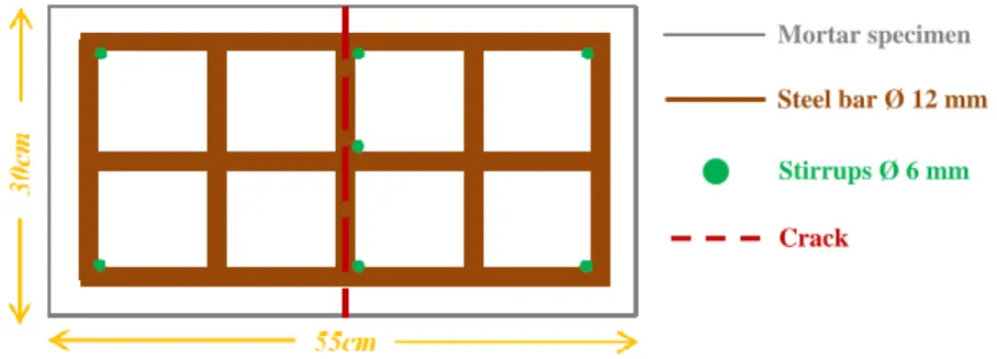
These specimens enable to perform experimental tests on slabs which are representative of the cooling tower shell. The experimented structure elements are concrete slabs of dimension 500×300×150 mm3 reinforced by two steel bars layers of Ø12mm. On some samples, the reinforcement layers are connected with Ø6mm stirrups. Concrete cover is equal to 30 mm (Figure 1). The first advantage of using two layers of reinforcement is to represent a real structure. The second objective is to test the effect of stirrups on the cracking behavior and on the interaction between stirrups corrosion and tensile steel bar corrosion, i.e., stirrups intercept the crack (Figure 2). On other specimens, the two reinforcement layers are connected only using an electrical wire which will be connected to an ampere meter to measure the galvanic current between the two layers when the crack path is carbonated from surface till the first steel layer. These slabs are cracked using the three-point bending test. Then, they are preconditioned and carbonated. Afterwards, they are subject to the same aspersion cycles applied on the centimeter scale specimens in order to make the comparison between these two scales. Corrosion products are analyzed by Raman spectroscopy to infer, according to one environmental condition, the type of corrosion developed in order to simulate the durability of the cooling towers.
In parallel, in order to compare the results of accelerated corrosion with the natural one, tests are performed on thirty years naturally corroded beams in the laboratory “Laboratoire des Matériaux et Durabilité des Constructions” LMDC de Toulouse. The results will be used as in-situ reference for validating the above developments.
Figure 1: Dimensions of the metric specimens
Section A-A
Section B-B
Mortar specimen Steel bar Ø 12 mm Stirrups Ø 6 mm
5
Figure 2: Stirrups intercepting the crack 2.2.2. Centimetric scale specimens
These specimens, easy to produce and manipulate, are adapted to perform the multiple experimental tests required for this study. The first laboratory tests are conducted at this scale. The drawn results will be validated by comparison with metric scale specimens results. Moreover, they serve in the development of an empirical model describing the kinetics of corrosion of reinforcement steel bar covered by the cracked mortar, for different environmental conditions. At this scale, prismatic specimens of size 70×70×280 mm3 with 6 mm steel bar are prepared (Figure 3). Once the specimens cracked by a three-point bending test, they are preconditioned in a climatic chamber at 55% relative humidity and 25°C temperature for 20 days. Then, the specimens are carbonated in another climatic chamber for one month at 3% CO2, 55% relative humidity and 25°C temperature.
Next, the carbonated specimens are placed in different cycles of humidity, temperature, rain, etc. At the end of each cycle, these specimens are analyzed by optical microscopy, Raman spectroscopy and scanning electron microscope to derive an empirical model of the kinetics of corrosion.
2.3. The cracking protocol
The cracking protocol is chosen in such a way that the cracks are representative of those encountered on cooling towers. The cracking protocol must meet the following:
Obtain a crack opening between 0.1 and 0.5 mm
Mitigate steel/concrete interface damage
Limit change in the chemical composition of the materials
Obtain a reproducibility of the crack width on the different test specimens
Be an efficient and easy to implement protocol
In spite of the multiple cracking protocols of cement materials that dominate the literature, none of them respond to the above mentioned criteria. For example, cracking by compression tests [14] as well as freezing/thaw cracking methods [15] generate diffused cracks. The expansive core method ([7], [8]) leads to a totally damaged steel/concrete interface. The traction test performed by imposing a direct traction on a steel bar embedded in concrete [16] leads to a transversal crack
Figure 3: Dimensions of the centimetric specimens
Crack Stirrups Ø 6 mm Steel bar Ø 12 mm Mortar specimen 7 0 mm cm
280 mm Protection against corrosion
Steel bar Ø 12 mm Mortar specimen
6
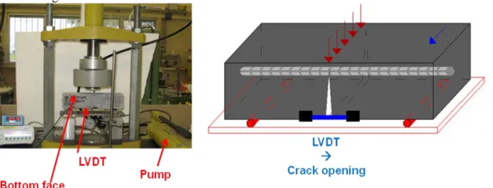
which is not representative of that found on the cooling towers. All of these methods cannot be retained. Two main cracking protocols possibilities remain: the shrinkage cracking protocol and the three points bending tests. Note that three different shrinkage protocols are possible and consist on applying a gradient of relative humidity or performing a heat treatment or thermal shocks. However, after a series of experimental tests, it was found that the three points bending test on 70×70×280 mm3 mortar specimens respects and fulfills the different characteristics required. Thus, this protocol is performed on the specimens thereafter. The crack opening is monitored by LVDT sensor as shown in Figure 4.
Figure 4: Three point bending test on 70×70×280 mm3 specimen 2.4. Exposure conditions
After performing the cracking protocol on the different specimens, as well as preconditioning, and carbonating them, the influence of different conditions on the kinetic of corrosion is studied. The main parameters are crack opening, temperature, rainfall duration and relative humidity.
2.4.1. Effect of the crack opening
The time needed for the corrosion initiation is a function of the diffusion properties of materials in uncracked concrete [17]. In the presence of a crack, the penetration of aggressive agents to the steel bar allows a quick initiation of corrosion [6], [18]. However, [19] indicates that for the smaller crack width, the self-healing of cracks is important and that can influence the propagation of corrosion. Moreover, [8] proposes that the propagation of corrosion may be favored by the “cover controlled cracking” induced by load and corresponding to the internal damage of the mortar surrounding the steel bar reinforcement. [20] adds that damage of mortar surrounding the steel bar is linked to load intensity and then to crack width. Thus, in this study, since the kinetic of corrosion is the main focus, then a range of crack widths between 0.1 mm and 0.5 mm must be tested to be representative of the physical cracks existing on cooling towers.
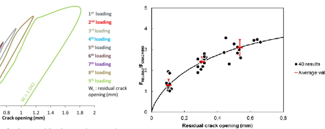
The three points bending test on 70×70×280 mm3 specimens enables to obtain cracks located in the midspan of the specimen. The crack width is also monitored by a loading/unloading cycle as illustrated in Figure 5. This figure shows that it is possible to obtain the residual crack widths required between 0.1 mm and 0.5 mm.
After cracking 40 specimens, it was visible that each crack opening corresponds approximately to the same reload to cracking force ratio as shown in the Figure 6. This means that the crack width obtained by this protocol is reproducible.
7 0 2 4 6 8 10 12 14 16 0 0.2 0.4 0.6 0.8 1 1.2 1.4 1.6 1.8 2 Lo ad (kN ) Crack opening (mm) 1stloading 2ndloading 3rdloading 4th loading 5thloading 6thloading 7thloading 8thloading 9thloading Wr: residual crack opening (mm)
Figure 5: Range of the residual crack opening
obtained by the three point bending test Figure 6: Loading versus residual crack opening
2.4.2. Temperature effect
In France, temperature usually ranges from 5°C to 40°C. According to [21], the kinetic of corrosion is limited at low temperature. Then only the effect of two temperatures will be tested: the 20˚C representative of a normal season and the 40˚C to represent a summer season.
2.4.3. Hydric conditions: rainfall duration and relative humidity
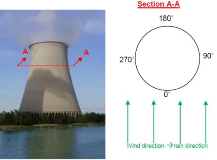
In this study, the wind is supposed to be unidirectional as shown in Figure 7. That implies that the side of the cooling tower facing the wind receives most of the rain, while the sides parallel to the wind direction receive less precipitation. On the other hand, the air saturated with steam produces a cloud, visible at the exit of the cooling towers. This uprising plume is pushed by the unidirectional wind, and therefore induces a high relative humidity on the side of the cooling towers located below this plume. This latter side is not directly exposed to precipitation. To study the development of the corrosion on the circumference of the cooling tower, we assume that it is divided into four parts as illustrated in Figure 7. The 0° is representative for the side subjected to rain more than the 90° and 270° sides. The 180° side is supposed to be exposed only to high relative humidity not to direct precipitation.
In the laboratory test, in order to compare the kinetic of corrosion on the 0° side and on the 90°, 270° sides, the effect of two rainfall duration is tested. Two humidification/drying cycles are performed per week. 30 minutes rain per cycle are representative of the 0° side while 3 minutes rainfall duration are representative of the 90° and 270° sides. To simulate the 180°, which is not exposed to rain, we will perform tests on some specimens in a high relative humidity (90%).
8
Figure 7: Different side of cooling tower 2.4.4. Natural environmental conditions
In each experience detailed before, only one environmental factor will be tested. The aim of the aforementioned experiments is to propose an empirical model describing the effect of the environmental conditions on the kinetic of corrosion. In order to verify the accuracy of this model, it is important to test it while all the environmental conditions vary simultaneously. For that, some cracked specimens will be subjected to the corrosion after carbonation in the environmental conditions of Saclay. In these conditions, all the above environmental factors (temperature, rainfall duration and humidity) vary at the same time. In details, the relative humidity and the temperature will be registered continuously by a temperature humidity recorder pack. Rainfall duration will be collected from the weather station of CEA Saclay.
3. First results
3.1. Quantification of the damage length of the steel/mortar interface
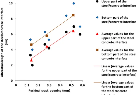
The three points bending test leads to a degradation of the mortar/steel interface for several centimeters long from both sides of the crack. This damage is a consequence of crack formation which induces a strong discontinuity between mortar and steel strains. [20], [22] indicate that the carbon dioxide diffuses on the concrete/steel interface through the intersection area between the crack and the steel bar. Moreover, [16] adds that independently from the crack opening, the concrete/steel interface at the crack tip is carbonated even though the carbonation is still superficial on the remaining surface of the beam. This is supported by [8] who adds that corrosion develops along the whole carbonated damaged concrete/steel interface. Thus, since the carbonation of the concrete/steel interface causes its depassivation and, therefore, corrosion initiation, it is interesting to quantify the length of the damaged concrete/steel interface. The later, corresponds to the carbonation length according to [8]. Therefore, to quantify this length, it is sufficient to perform the phenolphthalein test on the carbonated mortar/steel interface after breaking the specimen to two parts and taking the bar out. This test was done on 10 specimens with crack openings ranging from 0.1 mm to 0.5 mm after carbonation for 30 days. The results obtained Figure 8 show that the length of damaged steel/mortar interface is proportional to the crack opening. The same figure shows also that the damage on the mortar/steel interface is higher on the bottom side of the bar than that on the upper side of the bar (the upper and bottom side are considered with respect to the mortar casting direction). This is due to the « casting direction » that leads to a poor quality in the bottom side of
9
the mortar/steel interface, thus enable a propagation of the micro-cracks for a larger length than on the upper part.
0 2 4 6 8 10 0 0.1 0.2 0.3 0.4 0.5 0.6 A lt e ra ti on le ng th of t he s te e l/ conc re te int e rf ac e (c m )
Residual crack opening (mm)
Upper part of the steel/concrete interface
Bottom part of the steel/concrete interface
Average values for the upper part of the steel concrete interface Average values for the bottom part of the steel concrete interface Linear (Average values for the upper part of the steel concrete interface) Linear (Average values for the bottom part of the steel concrete interface)
Figure 8: damage length of steel concrete interface vs residual crack opening (data of 10 samples) 4. Conclusion
Corrosion propagation induced by carbonation in crack’s tip could be a factor threatening the durability of cooling towers. A two-year experimental program is set to identify and model the kinetics of corrosion in the damaged areas of the steel-mortar interface intercepting the crack, taking into account the effect of environmental conditions representative of those on cooling towers (sun, rain, wind , humidity ...). The work done so far permits the definition of the cracking protocol (three points bending) that allows obtaining cracks which are representative of those existing on cooling towers. Moreover, the length of steel/mortar damaged interface with respect to crack opening is quantified. It was found that this length is proportional to the crack opening. In addition, it was shown that the casting direction increases the damaged interface length at the lower part of steel bars. Afterwards, the effect of environmental conditions on the corrosion will be analyzed
5. Acknowledgment
This research was supported by grants from the EDF and CEA. The materials and equipments required for this research are provided by “Commissariat à l'énergie atomique et aux énergies alternatives” and “Laboratoires des Matériaux et Durabilité des Constructions LMDC de Toulouse.
6. References
[1] R. Witasse, “Contribution à la compréhension du comportement d’une coque d'aéroréfrigérant vieilli : définition d'un état initial, influence des effets différés sous chargements hydro-mécaniques,” thèse INSA LYON, 2000.
[2] R. Dutron and A. Mommens, Corrosion des armatures dans le béton armé. Centre National de recherches scientifiques et techniques pour l’industrie cimentaire CRIC, 1964.
10
[3] P. Schießl and M. Raupach, “Laboratory Studies and Calculations on the Influence of Crack Width on Chloride-Induced Corrosion of Steel in Concrete,” ACI Mater. J., vol. 94, no. 1, 1997.
[4] N. Hearn and C. T. Morley, “Self-sealing property of concrete Experimental evidence,”
Mater. Struct., vol. 30, pp. 404–411, 1997.
[5] C. Edvardsen, “Water Permeability and Autogenous Healing of Cracks in Concrete,” ACI
Mater. J. , vol. 96, no.4, pp.448-454, 1999.
[6] M. Ismail, A. Toumi, R. François, and R. Gagné, “Effect of crack opening on the local diffusion of chloride in cracked mortar samples,” Cem. Concr. Res., vol. 38, no. 8–9, pp. 1106–1111, Aug. 2008.
[7] S. Alahmad, A. Toumi, J. Verdier, and R. François, “Effect of crack opening on carbon dioxide penetration in cracked mortar samples,” Mater. Struct., vol. 42, no. 5, pp. 559–566, Jul. 2008.
[8] V. H. Dang, R. François, V. L’Hostis, and D. Meinel, “Propagation of corrosion in pre-cracked carbonated reinforced mortar,” Mater. Struct., pp. 1-21, Jun. 2014.
[9] O. I. S. Paradis, “Influence de la fissuration du béton sur la corrosion des armatures. Caractérisation des produits de corrosion formés dans le béton,” thèse Faculté des sciences et de génie, Université de Laval, 2009.
[10] D. Trejo, P. J. Monteiro, B. C. Gerwick Jr, and G. Thomas, “Microstructural design of concrete reinforcing bars for improved corrosion performance,” ACI Mater. J., vol. 97, no. 1, pp. 78–83, 2000.
[11] G. Slama and B. . Michaud, “Use of Shot Peening to Improve the SCC Resistance of Vapor Generator Tubes of PWR Nuclear Plants,” in 9th National Days on Prestrain Shot Peening, 1985.
[12] N. Ben Salah-Rousset, M. A. Chaouachi, and A. Chellouf, “Role of Surface Finishing on Pitting Corrosion of a Duplex Stainless Steel in Seawater,” ASM Int., vol. 5, pp. 225–231, 1996.
[13] V. Lapointe, “Initiation et propagation de la corrosion dans un élement de béton,” thèse Université Laval, 2009.
[14] W. Zhong and W. Yao, “Influence of damage degree on self-healing of concrete,” Constr.
Build. Mater., vol. 22, no. 6, pp. 1137–1142, Jun. 2008.
[15] S. Jacobsen, J. Marchand, and L. Boisvert, “Effect of cracking and healing on chloride transport in OPC concrete,” Cem. Concr. Res., vol. 26, no. 6, pp. 869–881, 1996.
[16] S. Alahmad, “Traitement des fissurations dans les ouvrages hydrauliques,” thèse INSA Toulouse, 2009.
[17] K. Tuutti, Corrosion of steel in concrete. Cement and Concrete Research Institute, 1982, p. 468.
11
[18] B. Huet, “Comportement à la corrosion des armatures dans un béton carbonaté . Influence de la chimie de la solution interstitielle et d ’une barrière de transport,” Insitutat National des Sciences Appliquées de Lyon, 2005.
[19] H.-W. Reinhardt and M. Jooss, “Permeability and self-healing of cracked concrete as a function of temperature and crack width,” Cem. Concr. Res., vol. 33, no. 7, pp. 981–985, Jul. 2003.
[20] A. Michel, A.O.S. Solgaard, B.J. Pease, M.R. Geiker, H. Stang, and J.F. Olesen, “Experimental investigation of the relation between damage at the concrete-steel interface and initiation of reinforcement corrosion in plain and fibre reinforced concrete,” Corros. Sci., vol. 77, pp. 308–321, Dec. 2013.
[21] D. Landol, “Corrosion et chimie de surfaces des matériaux,” Lausanne: presses
polytechniques et universitaires romandes. p. 553, 2003.
[22] R. François and J. C. Maso, “Effect of damage in reinforced concrete on carbonation or chloride penetration,” Cem. Concr. Res., vol. 18, no. 6, pp. 961–970, 1988.