OATAO is an open access repository that collects the work of Toulouse
researchers and makes it freely available over the web where possible
Any correspondence concerning this service should be sent
to the repository administrator:
[email protected]
This is an author’s version published in: http://oatao.univ-toulouse.fr/24331
To cite this version:
Shi, Hanbin
and Di Miceli Raimondi, Nathalie
and Fletcher, David F. and
Cabassud, Michel
and Gourdon, Christophe
Numerical study of heat
transfer in square millimetric zigzag channels in the laminar flow
regime. (2019) Chemical Engineering and Processing: Process
Intensification, 144. ISSN 0255-2701
Official URL:
https://doi.org/10.1016/j.cep.2019.107624
Numerical study of heat transfer in square millimetric zigzag channels in the
laminar flow regime
Hanbin Shi
a, Nathalie Di Miceli Raimondi
a,⁎, David F. Fletcher
b, Michel Cabassud
a,
Christophe Gourdon
aaLaboratoire de Génie Chimique, Université de Toulouse, CNRS, INPT, UPS, Toulouse, France bSchool of Chemical and Biomolecular Engineering, The University of Sydney, NSW, 2006, Australia
A B S T R A C T
The present work deals with the simulation of heat transfer in zigzag millimetric channels with square cross-section of 2 mm width in the laminar flow regime. They consist of periodic zigzag units composed of straight sections and 90° bends with a curvature radius of 1.5 mm. The influences of fluid velocity and straight section length on the thermo-hydraulic performances are investigated. The results showed that by increasing the flow velocity or decreasing the straight section length between two bends, a transition from periodic flow to non-periodic flow can be observed. A thermo-hydraulic performance factor based on heat transfer enhancement and pressure drop penalty compared with a straight channel is then discussed. It is observed that the ratio of the Nusselt number in the zigzag channels to that in the straight channel is always higher than one. This ratio increases with increasing Reynolds number and values up to 6.4 are reached in the cases studied (Pr = 6.13). When the pressure drop penalty is considered in the performance factor, an enhancement is still observed with a factor up to 2.5. It is shown that non-periodic flow is not particularly interesting in terms of thermo-hydraulic performance compared with periodic flow.
1. Introduction
In the process intensification field, new technologies like compact heat exchangers-reactors have been developed over the past decade to meet the trend of safer, cleaner, more effective and less energy-con-suming processes. They integrate two basic concepts of process in-tensification which are on one hand the miniaturization of the units and on the other hand the multi-functionalization of the apparatuses, ex-hibiting many advantages, such as good heat transfer performances, better temperature control and reactive volume confinement. Anxionnaz et al. [1] made a review of different kinds of compact heat exchangers-reactors and presented their applications at pilot scale or industrial scale. However, the reactor size reduction results in laminar flow operating conditions which does not favour transport phenomena. Consequently, complex designs are required in order to enhance mass and heat transfer. Wavy geometries are often applied in compact heat exchangers reactors since many techniques are today available and effective to design such geometries in various materials, such as metals or silicon carbide with good accuracy and low wall roughness. More-over they offer good heat exchange performances as they can decrease the thermal boundary layer thickness compared with straight tubes [2].
In order to explain the significant global enhancement of heat transfer in wavy channels compared with straight channels in laminar flow, many studies have been conducted to understand the relationship between hydrodynamics in wavy channels and heat transfer coeffi-cients. The secondary flow (Dean vortices) generated in curved pas-sages is the main effect for the improvement of mixing and heat transfer. Manglik et al. [3] studied numerically the steady forced con-vection in wavy plate-fin channels at low Reynolds number and found the generation of secondary flow which enhanced the heat transfer as well as the pressure drop penalty. Wang and Liu [4] presented various secondary flow structures in slightly curved microchannels with square cross-section. Their results suggested that the secondary flow created by channel curvature can increase the Nusselt number significantly and the friction factor moderately. Sui et al. [5,6] performed numerical and experimental studies of heat transfer for laminar liquid-water flow in three-dimensional wavy microchannels with rectangular cross- section. Their results also showed that the heat transfer performance in wavy microchannels was much better than that of straight microchannels with the same cross-section due to the generation of secondary flow and that the pressure drop penalty could be much smaller that the heat transfer enhancement. Fletcher and his coworkers [7–13] have
⁎Corresponding author.
E-mail address:[email protected](N. Di Miceli Raimondi). https://doi.org/10.1016/j.cep.2019.107624
conducted a variety of numerical studies for steady laminar flow and heat transfer in zigzag channels with different cross-sections and dif-ferent unit paths, including trapezoidal, serpentine, and sinusoidal channels. They found the similar conclusion that Dean vortices can enhance heat transfer greatly with relatively small pressure drop pen-alty. In addition to Dean vortices, mixing and heat transfer in a wavy passage can be enhanced by chaotic advection, which was described by Aref [14]. This flow behavior can be achieved in two-dimensional un-steady flow or in three-dimensional laminar un-steady flow. Liu et al. [15] presented a three-dimensional serpentine microchannel design as a way to implement chaotic advection to improve fluid mixing. Stroock et al. [16] and Aubin et al. [17] presented another passive method based on staggered herringbone mixer to generate chaotic flow to mix streams in microchannels at low Reynolds number. Jiang et al. [18] investigated mixing in curved microchannels numerically and experimentally. Their results showed that axial dispersion was substantially reduced relative to a straight channel due to mass transfer enhancement originating from the chaotic flow. Kumar and Nigam [19] studied the heat transfer numerically in a chaotic configuration of circular cross-section in the laminar regime. Their results showed a 25–36% enhancement in the heat transfer coefficient due to chaotic mixing while relative pressure drop was increased by 5–6%. Castelain et al. [20,21] have conducted experimental studies of chaotic advection in a twisted duct with square cross-section. They characterized the chaotic flow and found that it was sensitive to the initial conditions. A coiled heat exchanger based on chaotic advection was designed and it showed 15–18% higher effi-ciency than a helically coiled tube heat exchanger. Acharya et al. [22]
studied numerically and experimentally the heat transfer in an alter-nating axis coil, their results showed 6–8% higher in-tube heat transfer coefficient due to chaotic mixing compared with a conventional con-stant axis coil, with a pressure drop increase of 1.5–2.5%.
Adequate criteria should be used to attest of the efficiency of heat exchanger designs as described by Zheng et al. for heat exchangers with various enhanced surfaces [23]. Pati et al. [24] studied the heat transfer performances of two wavy channels: a raccoon channel and a serpen-tine channel. By comparing average Nusselt number as a function of Reynolds number, the raccoon channel appeared to perform better. However, by using a criterion that integrates both Nusselt number and pressure drop, the serpentine design can be considered as more effi-cient. This criterion defined as a thermo-hydraulic performance factor
PF is very useful to compare heat transfer technologies (Eq.(1)). This factor considers a straight tube as the reference. It is expressed as the ratio of the heat exchange capacity (global heat transfer coefficient hm
multiplied by heat exchange area AH) in the considered technology to
that in a straight tube divided by the ratio of the flow friction power in the technologyP to that in a straight tubeP0:
P P = PF (h A h A/ ) ( / ) m H 0 H,0 0 (1)
The flow friction power depends on the pressure drop Δp in the channel and the volumetric flowrate Q:
P= p Q (2)
In the present work, a numerical method is developed to study the
Nomenclature
A cross-sectional area (m²)
AH heat exchange area (m²)
Cp specific heat of the fluid (J kg−1K−1)
da element of cross-sectional area (m²)
dh hydraulic diameter (m)
dl element of perimeter length (m)
dX element of development length (m)
e thickness of aluminum plate (m)
eh heat transfer enhancement factor
f local Fanning friction factor
fi frequency i (Hz)
h heat transfer coefficient (W m−2K-1)
H enthalpy (J kg−1)
L channel length (m)
Lc curved section length (m)
Ls straight section length (m) m mass flow rate (kg s−1)
n normal vector at a cross-section Nbend number of bends
Nc number of divisions along the curved section
Nd number of divisions for the channel depth and width
Ne number of computational volume elements
Ns number of divisions along the straight section
Nunit number of periodic units
Nu local Nusselt number
p pressure (Pa)
p¯ area average pressure (Pa) Δp pressure drop (Pa)
P cross-section perimeter length (m)
P flow friction power (W) PF performance factor Pr Prandtl number q heat flux (W) ql thermal loss (W) Q volumetric flowrate (m3s−1) Rc radius of curvature (m) Re Reynolds number T temperature (K)
T¯ area average temperature (K)
T¯b bulk temperature (K)
T¯w peripheral average temperature at the wall (K)
ΔTml logarithmic mean temperature difference (K)
u velocity vector (m s−1)
u¯ mean fluid velocity (m s−1)
U global heat transfer coefficient (W m−2K-1)
x coordinate over the developed length (m)
y coordinate over the channel width (m)
z coordinate over the channel depth (m)
Greek symbols
θ angle between two straight sections (°)
λ thermal conductivity (W m−1K−1)
μ dynamic viscosity (Pa s)
ρ fluid density (kg m−3)
σT standard temperature deviation (K)
Subscripts
0 value in straight channel
m mean value over channel length
p process fluid
u utility fluid
w wall
x relative to axial location x
Superscripts
Continuity equation:
=
u
( ) 0 (3)
Momentum equation (Navier-Stokes):
= + + u u p µ u u ( ) ( ( T)) (4) Energy equation: = uH T ( ) ( ) (5)
u is the velocity vector, p the pressure, H the enthalpy and T the
tem-perature. The fluid physicochemical properties, such as density ρ, dy-namic viscosity μ and thermal conductivity λ, are assumed to be con-stant (at 25 °C), which make the Prandtl number concon-stant as well (Pr = 6.13). No phase change is considered. At the inlet, the fluid temperature is constant (equal to 20 °C) and fully-developed flow is assumed. The Poiseuille velocity profile at the inlet is approximated using the expressions suggested by Shah and London [33]. At the outlet,
zero static gauge pressure is set. At the walls, the no-slip condition and constant heat flux (H2) boundary condition are applied.
The simulations were carried out by solving the system of equations with the finite volume CFD code ANSYS CFX 16. All the calculations were performed at steady state in the laminar flow regime. The con-vective terms were discretized using a second-order bounded differen-cing scheme. The system was deemed to having reached a converged state when all the locally-scaled residuals fell below 10−6.
2.2. Computational domain and meshing method
For all the geometries studied, the computational domain consists of a three-dimensional zigzag channel of total length equal to roughly 0.1 m. Depending on the straight section length Ls, the number of bends
varies from one geometry to another (in total 7 geometries).Table 1
summarizes the number of bends Nbendand units Nunitfor each case. A
unit consists of two straight sections and two bends (Fig. 2(b)). All the geometries start and end with a straight section. However, to avoid the potential effects near the outlet which may influence the results, the last straight section is not taken into account in post-processing calcula-tions. Therefore the total length of the channel L considered in the rest of the article corresponds to a number of entire units.
A swept hexahedral mesh is used for the computational domain to provide an efficient and accurate resolution. In the cross-section, the mesh was constructed to be finer near the wall than at the centre, as shown inFig. 2(a), since the fluid velocity and temperature gradients are much higher there. Along the axial direction, the mesh was con-structed to be uniform, as shown inFig. 2(b). A mesh is defined by three numbers of divisions:
•
along the channel depth and width, Nd, corresponding to adis-cretized length equal to dh;
•
along the straight section, Ns, corresponding to a discretized lengthequal to Ls;
•
along the curved section in the bend, Nc, corresponding to adis-cretized length in the center of the channel equal to Lc.
3. Results and discussion
3.1. Parameters of interest: definitions
From the computed velocity, pressure and temperature fields, parameters of interest are calculated during post-processing. A co-ordinate reference that follows the main direction of the fluid is used. x is the axial coordinate, normal to the cross-section. At the channel inlet,
x = 0; at the channel outlet, x = L. y and z are the coordinates along
the channel width and depth, respectively. By convention, a bar above a parameter refers to an area or peripheral average value. The subscript m is used to refer to a mean value over the axial length. A represents the
Fig. 1. Schematic of the zigzag channel:
dh= 2 mm, Ls= 2–12 mm, Rc = 1.5 mm,
θ = 90°.
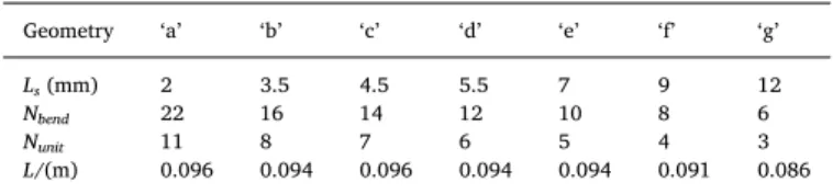
Table 1
Numbers of bends and units in the zigzag channels with different straight section lengths.
Geometry ‘a’ ‘b’ ‘c’ ‘d’ ‘e’ ‘f’ ‘g’
Ls(mm) 2 3.5 4.5 5.5 7 9 12
Nbend 22 16 14 12 10 8 6
Nunit 11 8 7 6 5 4 3
L/(m) 0.096 0.094 0.096 0.094 0.094 0.091 0.086
flow and heat transfer in a zigzag millimetric channel with square cross-sections under laminar flow r egime. T he g eometry o f t he channel, presented in Fig. 1, consists of periodic zigzag units. The geometric parameters are the width of the square section dh (equal to the
hy-draulic diameter), the radius of curvature of the bends Rc, the length of
the straight section Ls and the angle between two straight sections θ.
This pattern has been used to build compact heat exchangers-reactors designed by the Laboratoire de Génie Chimique (LGC, France), Boostec (French company) and the Commissariat à l’Energie Atomique et aux Energies Alternatives (CEA, France). Such devices (dH = 2 mm, Rc
= 1.5 mm, θ = 90° and Ls =7 mm) made of silicon carbide or stainless
steel have been successfully used to carry out highly exothermic reac-tions [25–27]. The straight channel with the same cross-section as the wavy channel is also studied as a reference.
The impacts of fluid v elocity a nd c hannel g eometry, i n t erms of straight section length between two bends, on the thermo-hydraulic performances are investigated. The objective is to examine how the residence time of the fluid in the curved section compared with that in the straight section affects the thermo-hydraulic performances. To our knowledge, such a study has not been carried out with square milli-metric zigzag channel. Heat transfer coefficients and friction factors are deduced from temperature and pressure fields and compared with those obtained in a straight channel. Fourier analysis is used to detect the onset of non-periodic flow a s a f unction o f R eynolds n umber and straight length between two bends. This method is very often used to describe flow t ransition b y s tudying t he e volution o f l ocal velocity components [28–32]. In the present work, it has been applied in an original way to the local Nusselt number and friction factor profiles along the channel. The heat transfer enhancement is then quantitatively reported. The results are finally discussed in terms of a performance factor that takes into account the pressure drop penalty considering that a zigzag channel and a straight channel of same cross-section should offer the same heat exchange capacity and heat or cool the same fluid flowrate.
2. Numerical method
2.1. Equations and solution method
The simulation work is based on the resolution of the equations for the conservation of mass, momentum and energy. For an in-compressible fluid and a steady state, these equations can be written as follows:
cross-sectional area of the channel and P the cross-section perimeter length. The heat transfer coefficient at axial location x is defined as:
= h x q T x T x ( ) ( ) ( ) w w b ¯ ¯ (6) whereqw is the wall heat flux,T¯w is the peripheral mean wall
tem-perature and T¯bis the bulk fluid temperature. The peripheral mean wall
temperature is calculated as:
= T x P T dl ( ) 1 w P w ¯ x (7)
wherePxrefers to the cross-section perimeter at axial location x. The
bulk fluid temperature is calculated using Eq.(8).Axrefers to the
sectional area at axial location x. n is the normal vector of the cross-section towards the main direction of the flow.
= u n T x Au T da ( ) 1 ¯ ( ) b A ¯ x (8)
The local Nusselt number Nu is defined as:
= Nu x( ) h x d( ) h
(9) The average Nusselt number Numbetween inlet and axial location x
is defined as: = Nu x x Nu dX ( ) 1 m x 0 (10)
The local Fanning friction factor f is defined as:
= = f x d u dp dX ( ) 1 2 h X x ¯2 ¯ (11) whereu¯is the mean fluid velocity, constant along the channel, andp¯is the cross-sectional area average pressure, calculated by:
= p x A p da ( ) 1 A ¯ x (12)
The average Fanning friction factor fmbetween inlet and axial
lo-cation x is defined as:
= f x x f dX ( ) 1 m x 0 (13)
The results will be discussed in terms of the Reynolds number Re defined as follows: = Re d u µ h¯ (14)
3.2. Grid independence studies
Grid independence studies were carried out to make sure that the
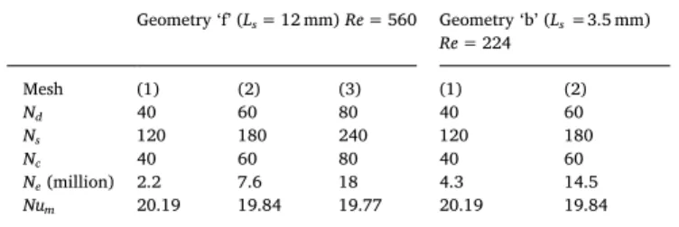
size of the grid did not influence the resulting solution for all the si-mulations carried out. The local Nusselt number Nu and local Fanning friction factor f were assessed for different mesh densities. Grid in-dependence studies for geometry ‘f’ at Re = 560 and geometry ‘b’ at
Re = 224 are presented. The variation of the local Nusselt number for
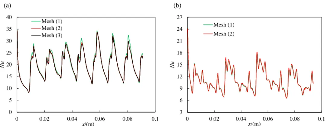
different meshes, whose characteristics are given inTable 2, is shown in
Fig. 3. For geometry ‘f’ at Re = 560, from mesh (2) to mesh (3), the local Nusselt number hardly varies and the global average Nusselt number (Num) varies by only 0.35%. Therefore mesh (2) is adequate for
this case study with 7.6 million volume elements (Ne) in the
computa-tional domain. For geometry ‘b’ at Re = 224, Numvaries by 0.54% while
Neis significantly increased. These two cases have been considered to
illustrate the grid independence study because they present two dif-ferent level of complexity in terms of local thermal behaviors as can be seen in Fig. 3. This will be discussed further in section3.3.2.
3.3. Local results
3.3.1. Analysis of the temperature field
As expected, it is observed that the temperature field over a cross-section in the zigzag channel is more homogeneous than in the straight channel. For example,Fig. 4(a) and (b) show the temperature field in the straight channel and in the zigzag channel ‘e’, respectively, at
x = 0.075 m (outlet of the 8thbend in the zigzag channel) for Re = 224.
In the straight channel, characterized by a laminar Poiseuille flow (Fig. 4(c)), the heating of the successive concentric flow layers occurs by thermal diffusion. In the zigzag channel, the Dean vortices generated by the bends (Fig. 4(d)) create radial mixing which improves the tem-perature homogenization over the channel cross-section.
For further comparison, the value of the relative maximum tem-perature difference (Tmax - Tmin)/ T¯ and the relative standard
tem-perature deviation T/ T¯ (Eq. (15)) over the cross-section at
x = 0.075 m for both channels are calculated at different Reynolds
numbers and shown inFig. 5.
= T T T da T ¯ ( ¯) ¯ T A A 1 2 x (15)
Fig. 2. Illustration of the mesh for one repeating unit on (a) the cross-section and (b) the wall. dh= 2 mm, Ls= 2–12 mm, Lc= 2.4 mm.
Table 2
Characteristics of the meshes used for geometry ‘f’ at Re = 560. Geometry ‘f’ (Ls= 12 mm) Re = 560 Geometry ‘b’ (Ls=3.5 mm) Re = 224 Mesh (1) (2) (3) (1) (2) Nd 40 60 80 40 60 Ns 120 180 240 120 180 Nc 40 60 80 40 60 Ne(million) 2.2 7.6 18 4.3 14.5 Num 20.19 19.84 19.77 20.19 19.84 4
(Tmax- Tmin)/T¯ and σTdecrease both in the zigzag channel and the
straight channel with increasing Reynolds number. (Tmax- Tmin)/T¯and
T/T¯in the zigzag channel are significantly smaller than in the straight
channel, indicating the temperature in the zigzag channel is more homogeneous as mentioned previously. For the design of compact heat exchangers-reactors, this is very favorable when exo- or endothermic reactions are carried out since it avoids extreme temperatures and therefore leads to better control of reactant conversion, limits the for-mation of by-products and the device operates under safer conditions.
3.3.2. Evolution of Nu and f versus Re
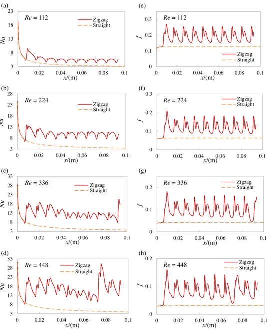
The results obtained in the zigzag channel ‘e’ are used to illustrate the flow and heat transfer and are compared with the results for the straight channel. The local Nusselt number Nu and Fanning friction factor f from the channel entrance to the exit of the 5thunit in the
zigzag channel for Re = 112–448 are shown inFig. 6. The profiles in the straight channel are also presented. In the straight channel, the local Nusselt number decreases along the channel (Fig. 6(a–d)). This is ty-pical of the thermal boundary layer development in laminar flow as a constant fluid temperature has been set at the channel inlet in the si-mulations. The asymptotic value of Nu obtained in the simulations at high x is consistent with the theory. Indeed Nusselt number of 3.091 should be reached for hydrodynamically and thermally fully-developed laminar flow in the case of square channels with (H2) thermal boundary condition for all Re [34]. The local Fanning friction factor in the straight channel is constant since a fully-developed laminar flow has been set at the channel entrance (Fig. 6(e–h)). The slight increase ob-served in the very first millimeters is due to the approximate laminar velocity profiles set at the inlet. The values of f fit with the theory that gives f = (14.227/Re) for fully- developed laminar flow [34].
In the zigzag channel, the evolution of Nu and f in the entrance zone perfectly fits with those observed in the straight channel as the zigzag channel starts with a straight section. Then, oscillations appear that correspond to the periodicity of the geometry studied. Both Nu and f start to increase just before the bends and decrease in the straight section lengths. It can be observed that Nu and f in the zigzag channel are significantly higher globally than those in the straight channel,
Fig. 3. Mesh influence on the local Nusselt number in (a) geometry ‘f’ for Re = 560 and (b) geometry ‘b’ for Re = 224.
Fig. 4. Temperature and velocity fields over the cross-section at x = 0.075 m in
(a, c) the straight channel and in (b, d) the zigzag channel ‘e’ for Re = 224. The black arrow is the tangential velocity.
Fig. 5. (a) Relative maximum temperature difference and (b) relative standard temperature deviation over the cross-section at x = 0.075 m in the straight channel
suggesting as expected that the bends enhance heat transfer but cause additional pressure loss. Nu increases with Re in the zigzag channel, while it is roughly constant in the straight channel. For both channel configurations, f decreases as Re increases. In the zigzag channel it is particularly observable that the oscillations in Nu and f are regular at low Reynolds number from the 4th bend (Fig. 6(a,b,e,f)), having a
constant amplitude. From that bend, the flow can be considered as both hydrodynamically and thermally developed. The fluid behaves in the same way in each bend and each straight section. However, at higher Reynolds number (Fig. 6(c,d,g,h)), the amplitude of the oscillations becomes irregular whatever the axial location. Regarding Nu, the am-plitude tends to decrease along the channel until a significant jump is observed. The jump is observed earlier as Reynolds number increases. This irregular behavior in wavy channels has already been observed and has been interpreted as chaotic flow [35,13], in this paper it is named as non-periodic flow.
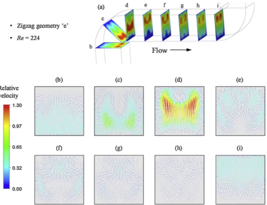
To understand the transition from periodic flow to non-periodic flow, the velocity fields in both cases are studied. Velocity fields and relative tangential velocity vectors at different cross-sections between two bends for Re = 224 and 448 are shown inFigs. 7 and 8. The relative tangential velocity is defined as the tangential velocity divided by the
mean fluid velocity. For both Reynolds numbers, at the entrance of a bend, the high velocity zone is close to the inner side of that bend (corresponding to the outer side of the previous bend) and then moves towards the outer side due to centrifugal effects (Fig. 7(a) and
Fig. 8(a)). In cross-section (b), the relative tangential velocity vectors are mainly towards the inner side of the bend under the effect of cen-trifugal forces created by the previous bend. For the following cross-sections (c–h), Dean vortices appear, and the number of vortices varies from two to four. Their intensity becomes stronger in the bend and decreases along the straight channel. The direction of the relative tan-gential velocity changes and shifts towards the inner side of the next bend as shown in cross-section (i). However, it has to be underlined that in cross-section (h), for Re = 224 (Fig. 7), the tangential movement has almost vanished while the Dean vortices are still perceptible for
Re = 448 (Fig. 8). By comparing the cross-section (b) and (i), the re-lative tangential velocity field is almost the same at the entrances of the two bends for Re = 224 (Fig. 7). The only change is the direction, suggesting the flow behavior in the next bend returns to that of the previous bend. For Re = 448, the flow behavior in the coming bend does not return to that of the previous bend, as the instability created in this bend is still significant (Fig. 8). This flow regime is more irregular
Fig. 6. (a–d) Local Nusselt number and (e–h) Fanning friction factor profiles in the straight channel and zigzag channel ‘e’ for Re = 112–448.
and unstable, different from that at a Reynolds number of 224 where the fluid spends more time in the straight section.
3.3.3. Evolution of Nu and f versus Ls
Different zigzag channels with straight section lengths ranging from 3.5 mm to 12 mm are studied at Re = 224. The local Nusselt number Nu
and friction factor f from the channel entrance to the exit of the last unit of the zigzag channel are shown inFig. 9(a–j). The local Nusselt number and friction factor in a straight channel with the same cross-section at the same Reynolds number are also presented as a reference. It is observed that the transition between periodic flow (Fig. 9(d–e, i–j)) and non-periodic flow (Fig. 9(a–c, f–h)) occurs as the straight section
Fig. 7. (a) Velocity fields and (b–i) relative tangential velocity vectors at different cross-sections between two bends at Re = 224 in zigzag channel ‘e’. The top side in
(b–i) corresponds to the outer side of the bend studied.
Fig. 8. (a) Velocity fields and (b–i) relative tangential velocity vectors at different cross-sections between two bends at Re = 448 in zigzag channel ‘e’. The top side in
(b–i) corresponds to the outer side of the bend studied.
length is decreased. By analogy with part 3.3.2, where the non-periodic flow occurs by increasing the fluid velocity, it is confirmed that redu-cing the residence time between two bends favours the occurrence of a non-periodic flow regime.
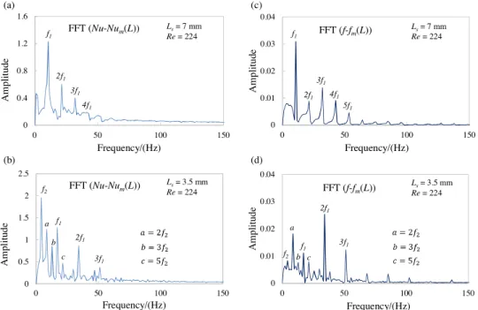
3.3.4. Fourier analysis for non-periodic flow detection
A fast Fourier analysis was used to analyze the local Nusselt number and the friction factor in the zigzag channels. It converts the signal of Nusselt number and friction factor from the spatial domain to the fre-quency domain. The fast Fourier transform analysis is applied to (Nu –
Num(L)) and (f– fm(L)). Num(L) and fm(L) represent the global Nusselt
number and friction factor, respectively, calculated by averaging the local values from the channel inlet (x = 0) to the outlet (x = L). Here two cases are presented with the straight section length Ls equal to
7 mm and 3.5 mm at Re = 224 as shown inFig. 10. For zigzag channels ‘e’ with Ls=7 mm, the Fourier transform spectrum of Nusselt number
contains a unique primary frequency f1and its harmonic frequencies
2f1, 3f1, 4f1, etc. (Fig. 10(a)). f1is equal to the frequency of the bend in
the channel given by:
= + f u Ls Lc 1 ¯ (16)
The same observation can be made in the spectrum of the friction factor where the basic frequency is the same (Fig. 10(b)). These results show that the flow is in a periodic regime with a single oscillation frequency. For zigzag channels ‘b’ with Ls =3.5 mm (Fig. 10(b,d)),
another basic frequency f2appears in addition to the primary frequency
f1in the spectrums of Nusselt number and friction factor. The ratio f2/ f1
is a quarter. All the other spectral peaks are the harmonic frequencies of these two basic frequencies f1 and f2. The flow is no longer in the
periodic regime but non-periodic. This analysis methodology has been widely used for flow transition scenario studies although classically it is applied to velocity, not to Nusselt number or friction factor [28–32].
With the help of fast Fourier transform analysis, the flow pattern periodic or non-periodic for different channel configurations at dif-ferent Reynolds numbers can be distinguished. A map is plotted to show the flow regime as a function of Reynolds number and normalized straight section length Ls/dh(Fig. 11). For the data marked with a full
triangle in the figure, the simulation converged but the grid in-dependence was not achieved. A transient solver has been tested to simulate the condition where Re = 560 and Ls=3.5 mm as transient
laminar flow was observed in analogous geometries [36]. In the present case, the transient simulations converge towards a steady solution but the converged solution still depends on the mesh grid size. Reducing the mesh size is impractical. In the map, a boundary line between periodic and periodic flow can be observed. As mentioned before, the non-periodic flow regime can be achieved by decreasing the straight section length between two bends or by increasing the fluid velocity.
3.4. Global results
3.4.1. Average Nusselt number and friction factor
The average Nusselt number Numand friction factor fmin the
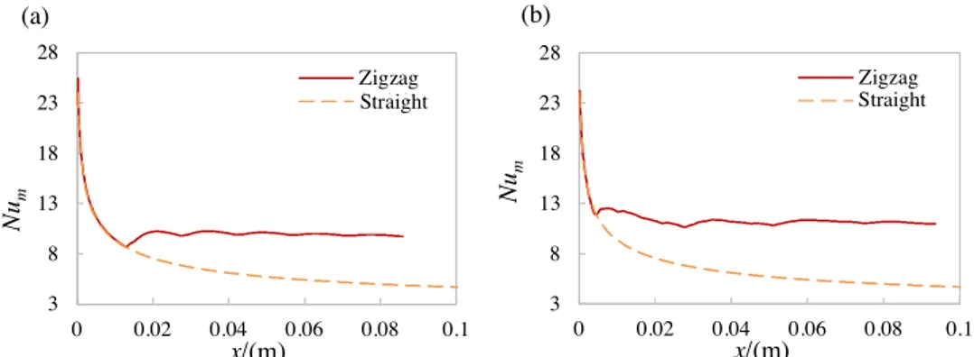
dif-ferent zigzag channels at difdif-ferent Reynolds numbers were also studied. Two cases of average Nusselt number at Re = 224 are presented in
Fig. 12: one is in the steady periodic regime with a straight section length of 12 mm, whilst the other is in the non-periodic regime with a straight section length of 3.5 mm. The average Nusselt number in the straight channel is also presented. In both regimes, it can be seen that the Nusselt number quickly becomes stable while, in the straight channel, it decreases along the simulated length. The average Nusselt
number stabilizes after several bends, indicating the thermal boundary layer has been fully-developed for both flow regimes within a zigzag channel length of few centimeters.
The average Nusselt number and friction factor at axial coordinate x = 0.086 m (channel length of geometry ‘g’) was chosen as a re-presentation of the global average Nusselt number and friction factor for all the zigzag channels studied, where the thermal boundary layer is considered as fully−developed (denoted by an infinity superscript). The Nusselt number and friction factor are plotted as a function of Ls/
dh, as presented inFig. 13. InFig. 13(a), the Nusselt number increases
with increasing Reynolds number for all the channel geometries. Its variation for different Ls/dhseems to be random at the same Reynolds
number, indicating the influence of the straight section length on the heat transfer is not obvious in the zigzag channel. The friction factor decreases with increasing Ls/dh or Reynolds number, as shown in
Fig. 13(b).
3.4.2. Validation of the simulation results by experiments
An experimental setup, presented inFig. 14, is used to study heat transfer in a prototype millimetric heat-exchanger which consists of
Fig. 10. Fast Fourier transform analysis for Nusselt number and friction factor in zigzag channels with straight section lengths of (a,c) 7 mm and (b,d) 3.5 mm at
Re = 224.
Fig. 11. Map of periodic flow and non-periodic flow in the zigzag channels
three plates: a plate made of aluminum sandwiched between a ‘process’ plate and a ‘utility’ plate. The three plates are assembled together using double-sided adhesives cut to fit the channel designs. The aluminum plate is very thin (eAl= 1 mm thickness) and presents a high thermal
conductivity (λAl= 237 W m−1K−1) so that its thermal resistance is
very low (eAl/λAl= 4.2⨯10-6m2K W-1) compared to the maximal global
thermal resistance 1/U = 2.5⨯10-4m2K W-1measured in the
experi-ments. The ‘process’ plate and the ‘utility’ plate, of 10 mm thickness, are made of PolyMethylMethAcrylate (PMMA), its thermal conductivity is
very low to limit the thermal losses (λPMMA= 0.19 W m−1K−1). In the
‘process’ plate, a zigzag channel is etched whose geometric parameters are the same as the geometry ‘e’ simulated, with just a different total length (0.6 m in the experiment compared with 0.1 m in the simula-tion). In the ‘utility’ plate, a straight channel with a rectangular cross-section (12 mm width, 6 mm depth) is etched so that it largely covers the zigzag channel in the ‘process’ plate both in the flow direction and radial direction. The two channels in the two plates (zigzag channel in ‘process’ plate, straight channel in ‘utility’ plate) are face to face and at
Fig. 12. Average Nusselt number in straight channel and zigzag channel at Re = 224: (a) Ls= 12 mm; (b) Ls=3.5 mm.
Fig. 13. Fully-developed average Nusselt number (a) and friction factor (b) in the zigzag channels.
Fig. 14. Experimental setup for the
determi-nation of the heat transfer coefficient of wavy millimetric channels. The heat exchanger re-actor prototype is composed of a PMMA ‘pro-cess’ plate where the millimetric zigzag channel is etched (top view in (a)), a PMMA ‘utility’ plate where a larger rectangular straight channel is etched (front view in (c)), both separated by an aluminum plate (side view in (b)).
=
q m Cp P p, Tp ql (17)
wheremp is the mass flow rate and CP p, is the specific heat of the
process fluid. The global heat transfer coefficient (U) of the mock-up can be calculated by:
=
U q
AH Tml (18)
where ΔTml is the logarithmic mean temperature difference. For the
sandwiched mock-up, the overall conductance is:
= + + UA h A e A h A 1 1 1 H p H p Al Al H u H u , , (19)
where hp and hu are the convection heat transfer coefficient of the
process fluid and utility fluid, AH,p, AH,uare the heat transfer areas in
‘process’ plate and ‘utility’ plate, respectively. In this work, AHis
con-sidered equal to AH,p. The heat transfer coefficient huof utility fluid
(Re > 104during the experiment) can be deduced from the correlation
of Nusselt proposed by Gnielinski [37]:
= = + Nu h d Re Pr d L Pr Pr 0.012 ( 280) [1 ( ) ] ( ) u u h u u u u hu u u w , 0.87 0.4 2 3 0.11 (20)
Pruis close to 4 in the experiments. Assuming the wall is at the
temperature of the process fluid, Prw is estimated to be around 6.
Therefore, it can be reasonably assumed that
( )
PrPru 0.11=1w . The heat
transfer coefficient of the process fluid hpthen can be calculated from
Eq.(19). The Nusselt number Nupcan be furtherly obtained by:
= Nup h dp h p
p ,
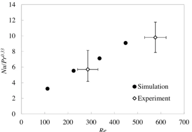
(21) The experimental and simulation results of the geometry ‘e’ are shown inFig. 15where Nu/Pr0.33is plotted as a function of Re as the Pr
in the simulation and experiment is different. The power factor of Pr is 0.33 as suggested by Sieder and Tate correlation in laminar flow or Colburn correlation in turbulent flow [38]. It is observed that the si-mulation results fit well with the experimental data.
3.4.3. Heat transfer enhancement
As discussed above, the zigzag channel configuration enhances heat transfer compared with the straight channel with the same cross-sec-tion. This heat transfer enhancement is accompanied by higher pressure drop which has been noted. The heat transfer enhancement factor is defined as: = e Nu Nu Nu m 0 (22)
where Nu0 is the Nusselt number in a straight channel. As mentioned
before, for hydraulically and thermally developed laminar flow,
=
Nu0 3.091for a square channel with H2 thermal boundary condition [34]. eNu for the studied zigzag configurations at different Reynolds
numbers is plotted inFig. 16. It is observed that the presence of the bends improves the heat transfer significantly, notably at high fluid velocity.eNu increases with increasing Reynolds number for the
dif-ferent zigzag configurations. Its variation is random in terms of Ls/dh,
indicating the impact of non-periodic flow on heat transfer enhance-ment is not obvious. Here the pressure drop penalty is not taken into account.
3.4.4. Thermo-hydraulic performance factor
Webb and Eckert have proposed a different way to compare the relative performance of heat exchangers with rough surface tubes compared with heat exchangers with smooth surface tubes [39]. They proposed a list of parameters of interest depending on user constraints (for instance the ratio of the surface areas while constant flow friction power and volumetric flowrate are imposed). By analogy, in the present study, each zigzag channel is compared with a straight channel of the same cross-section assuming that:
•
both configurations must provide the same heat exchange capacity in order to heat or cool a fluid from a fixed temperature to a desired one (Eq.(23));•
the fluid flowrate is imposed (Eq.(24)).=
hm AH h A0 H,0 (23)
=
Q Q0 (24)
Therefore, from Eqs.(1) and(2), the performance factor can be expressed as follows: = PF p p 0 (25) In other words, the performance factor considered in the present study compares the pressure drop in a straight channel with that in a zigzag channel with the same cross-section and flow rate. In order to
Fig. 16. Heat transfer enhancement in the zigzag channels studied. Fig. 15. Comparison of Nu/ Pr0.33 from simulation and experiment for the
zigzag channel ‘e’. The experimental error is estimated from the accuracy of the sensors ( ± 0.2 kg h−1 for the process fluid flowrate, ± 3 kg h−1 for the utility
fluid flowrate, ± 0.3 °C for the temperatures).
the middle of each plate.
In the experiments, hot water at about 60 °C is introduced in the ‘process’ plate. It is cooled by cold water at ambient temperature in the ‘utility’ plate, with a volumetric flowrate of 300 L.h−1. The two fluids
flow co-currently. The inlet and outlet temperatures of the two fluids are measured. In order to decrease the thermal loss, the exchanger is surrounded by insulation foam. The process fluid is taken into account for the calculation of heat transfer coefficient as it ha s la rger tem-perature difference. From the temtem-perature difference (ΔTp) in process
fluid, the heat exchange flux between the two fluids (q) can be calcu-lated using Eq. (17). The thermal losses (ql) have been previously
es-timated by introducing just the process fluid (Eq. (17) with q = 0), with no flow in the utility plate.
obtain the same heat exchange capacity, the length of both channels will be different. The pressure drop can be expressed as a function of the mean fluid velocity, the Fanning friction factor, the hydraulic diameter and the channel length:
= p u f L d 2 h ¯2 (26) For same flowrate and hydraulic diameter, the performance factor simplifies to: = PF f L f L 0 0 (27) where L0 is the straight channel length and f0 the Fanning friction
factor for fully-developed laminar flow in square straight channel [32]:
= f
Re
14.227
0 (28)
Considering the same cross-section in the zigzag and straight channels, the ratio of channel lengths is equal to the ratio of heat ex-change areas. From Eq.(23), the following expression is then obtained:
= = = L L A A h h Nu Nu H m m 0 H,0 0 0 (29)
From Eqs. (27)–(29), the performance factor can finally be ex-pressed as follows: = PF Re Nu f Nu 14.227 m 0 (30)
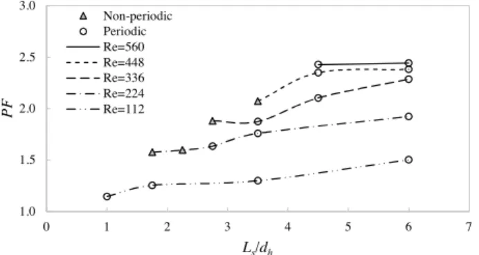
PF for the channel configurations studied at different Reynolds
numbers is presented inFig. 17. For all the cases studied, PF is greater than one, suggesting that the bends significantly enhance the thermo-hydraulic performances of the channel. That means the zigzag channel brings less significant pressure drop compared with the heat transfer enhancement. PF increases with increasing Reynolds number or Ls/dh.
The increase with Reynolds number is particularly important at low Re. From Re = 336, the increase becomes moderate with increasing Rey-nolds number. Concerning the impact of the straight section, decreasing its length to reach non-periodic flow regime is not interesting in terms of thermo-hydraulic performances in the cases studied. Finally, it has to be noted that by increasing Ls/dh, the zigzag design will get closer to the
straight channel. Therefore, the different curves should converge to-wards PF = 1 for very high Ls/dh, depicting a bell-shaped curve with an
optimal range of Ls/dhvalues depending on Re. The observed plateaus
for Re = 448 and Re = 560 may suggest that this optimum is between
Ls/dh= 4.5 and 6 for these conditions.
4. Conclusions
A numerical method based on the use of the software ANSYS CFX has been developed to study the flow and heat transfer in millimetric zigzag channels with square cross-section and 2 mm hydraulic
diameter. The simulations are carried out for the steady laminar flow regime with Reynolds numbers ranging from 112 to 560 and a Prandtl number of 6.13. The channel geometry in terms of straight section length between two bends from 2 mm to 12 mm has been investigated. The flow and heat transfer in a straight channel with the same cross-section is also studied as a reference. The numerical method is validated by comparing with experimental data for Nusselt number obtained in a heat transfer experiment.
The results show that local Nusselt numbers and Fanning friction factors vary along the zigzag channels according to oscillating curves. The amplitude of the oscillations is constant with periodic flow but varies in the case of non-periodic flow. Based on Fourier analysis, a map has been provided which allows to distinguish the conditions in terms of Reynolds number and straight section length that gives a periodic flow or a non-periodic flow. Non-periodic flow is obtained by increasing the fluid velocity or by decreasing the straight section length. For
Re = 560 and Ls/dh= 3.5, the flow instability created by the bends was
too great for steady laminar flow to develop. The heat transfer en-hancement and thermo-hydraulic performance factor are quantitatively discussed, which show that the zigzag channel enhances the heat transfer strongly and increases relatively less significantly the pressure drop compared with the straight channel. It appeared that non-periodic flow is not particularly interesting in terms of thermo-hydraulic per-formances. All these data should be very useful for the design of high-performance heat exchangers-reactors. The impact of other geometric parameters, such as the hydraulic diameter, the curvature radius of the bends and their angle should be studied to complete this work.
Acknowledgment
This work was performed using HPC resources from CALMIP.
References
[1] Z. Anxionnaz, M. Cabassud, C. Gourdon, P. Tochon, Heat exchanger/reactors (HEX reactors): concepts, technologies: state-of-the-art, Chem. Eng. Process. Process Intensif. 47 (2008) 2029–2050,https://doi.org/10.1016/j.cep.2008.06.012. [2] Z. Anxionnaz-Minvielle, M. Cabassud, C. Gourdon, P. Tochon, Influence of the
meandering channel geometry on the thermo-hydraulic performances of an in-tensified heat exchanger/reactor, Chem. Eng. Process. Process Intensif. 73 (2013) 67–80,https://doi.org/10.1016/j.cep.2013.06.012.
[3] R.M. Manglik, J. Zhang, A. Muley, Low Reynolds number forced convection in three-dimensional wavy-plate-fin compact channels: fin density effects, Int. J. Heat Mass Transf. 48 (2005) 1439–1449,https://doi.org/10.1016/j.ijheatmasstransfer. 2004.10.022.
[4] L. Wang, F. Liu, Forced convection in slightly curved microchannels, Int. J. Heat Mass Transf. 50 (2007) 881–896,https://doi.org/10.1016/j.ijheatmasstransfer. 2006.08.016.
[5] Y. Sui, C.J. Teo, P.S. Lee, Y.T. Chew, C. Shu, Fluid flow and heat transfer in wavy microchannels, Int. J. Heat Mass Transf. 53 (2010) 2760–2772,https://doi.org/10. 1016/j.ijheatmasstransfer.2010.02.022.
[6] Y. Sui, P.S. Lee, C.J. Teo, An experimental study of flow friction and heat transfer in wavy microchannels with rectangular cross section, Int. J. Therm. Sci. 50 (2011) 2473–2482,https://doi.org/10.1016/j.ijthermalsci.2011.06.017.
[7] N.R. Rosaguti, D.F. Fletcher, B.S. Haynes, Laminar flow and heat transfer in a periodic serpentine channel with semi-circular cross-section, Int. J. Heat Mass Transf. 49 (2006) 2912–2923,https://doi.org/10.1016/j.ijheatmasstransfer.2006. 02.015.
[8] R. Gupta, P.E. Geyer, D.F. Fletcher, B.S. Haynes, Thermohydraulic performance of a periodic trapezoidal channel with a triangular cross-section, Int. J. Heat Mass Transf. 51 (2008) 2925–2929,https://doi.org/10.1016/j.ijheatmasstransfer.2007. 09.017.
[9] N.R. Rosaguti, D.F. Fletcher, B.S. Haynes, Laminar flow and heat transfer in a periodic serpentine channel, Chem. Eng. Technol. 28 (2005) 353–361,https://doi. org/10.1002/ceat.200407148.
[10] P.E. Geyer, N.R. Rosaguti, D.F. Fletcher, B.S. Haynes, Thermohydraulics of square-section microchannels following a serpentine path, Microfluid. Nanofluidics 2 (2006) 195–204,https://doi.org/10.1007/s10404-005-0062-7.
[11] P.E. Geyer, D.F. Fletcher, B.S. Haynes, Laminar flow and heat transfer in a periodic trapezoidal channel with semi-circular cross-section, Int. J. Heat Mass Transf. 50 (2007) 3471–3480,https://doi.org/10.1016/j.ijheatmasstransfer.2007.01.050. [12] N.R. Rosaguti, D.F. Fletcher, B.S. Haynes, Low-Reynolds number heat transfer
en-hancement in sinusoidal channels, Chem. Eng. Sci. 62 (2007) 694–702,https://doi. org/10.1016/j.ces.2006.09.045.
[13] Z. Zheng, D.F. Fletcher, B.S. Haynes, Chaotic advection in steady laminar heat
transfer simulations: periodic zigzag channels with square cross-sections, Int. J. Heat Mass Transf. 57 (2013) 274–284,https://doi.org/10.1016/j.
ijheatmasstransfer.2013.12.056.
[14] H. Aref, Stirring by chaotic advection, J. Fluid Mech. 143 (1984) 1,https://doi.org/ 10.1017/S0022112084001233.
[15] R.H. Liu, M.A. Stremler, K.V. Sharp, M.G. Olsen, J.G. Santiago, R.J. Adrian, H. Aref, D.J. Beebe, Passive mixing in a three-dimensional serpentine microchannel, J. Microelectromech. Syst. 9 (2000) 190–197.
[16] A.D. Stroock, S.K. Dertinger, A. Ajdari, I. Mezić, H.A. Stone, G.M. Whitesides, Chaotic mixer for microchannels, Science 295 (2002) 647–651.
[17] J. Aubin, D.F. Fletcher, J. Bertrand, C. Xuereb, Characterization of the mixing quality in Micromixers, Chem. Eng. Technol. 26 (2003) 1262–1270,https://doi. org/10.1002/ceat.200301848.
[18] F. Jiang, K.S. Drese, S. Hardt, M. Küpper, F. Schönfeld, Helical flows and chaotic mixing in curved micro channels, AIChE J. 50 (2004) 2297–2305,https://doi.org/ 10.1002/aic.10188.
[19] V. Kumar, K.D.P. Nigam, Laminar convective heat transfer in chaotic configuration, Int. J. Heat Mass Transf. 50 (2007) 2469–2479,https://doi.org/10.1016/j. ijheatmasstransfer.2006.12.029.
[20] C. Castelain, A. Mokrani, Y. Le Guer, H. Peerhossaini, Experimental study of chaotic advection regime in a twisted duct flow, Eur. J. Mech. BFluids. 20 (2001) 205–232,
https://doi.org/10.1016/S0997-7546(00)01116-X.
[21] H. Peerhossaini, C. Castelain, Y. Le Guer, Heat exchanger design based on chaotic advection, Exp. Therm. Fluid Sci. 7 (1993) 333–344,https://doi.org/10.1016/ 0894-1777(93)90056-O.
[22] N. Acharya, M. Sen, C. Hsueh-Chia, Heat transfer enhancement in coiled tubes by chaotic mixing, Int. J. Heat Mass Transf. 35 (1992) 2475–2489,https://doi.org/10. 1016/0017-9310(92)90090-F.
[23] Z. Zheng, A.M. Johnston, D.F. Fletcher, B.S. Haynes, Heat exchanger specification: coupling design and surface performance evaluation, Chem. Eng. Res. Des. 93 (2015) 392–401,https://doi.org/10.1016/j.cherd.2014.04.015.
[24] S. Pati, S.K. Mehta, A. Borah, Numerical investigation of thermo-hydraulic transport characteristics in wavy channels: comparison between raccoon and serpentine channels, Int. Commun. Heat Mass Transf. 88 (2017) 171–176,https://doi.org/10. 1016/j.icheatmasstransfer.2017.09.001.
[25] S. Elgue, A. Conté, C. Gourdon, Y. Bastard, Direct fluorination of 1,3-dicarbonyl compound in a continuous flow reactor at industrial scale, Chem. Today 30 (2012). [26] L. Despènes, S. Elgue, C. Gourdon, M. Cabassud, Impact of the material on the
[27] N. Di Miceli Raimondi, N. Olivier-Maget, N. Gabas, M. Cabassud, C. Gourdon, Safety enhancement by transposition of the nitration of toluene from semi-batch reactor to continuous intensified heat exchanger reactor, Chem. Eng. Res. Des. 94 (2015) 182–193,https://doi.org/10.1016/j.cherd.2014.07.029.
[28] G.E. Karniadakis, G.S. Triantafyllou, Three-dimensional dynamics and transition to turbulence in the wake of bluff objects, J. Fluid Mech. 238 (1992) 1–30,https://doi. org/10.1017/S0022112092001617.
[29] A.M. Guzmán, C.H. Amon, Dynamical flow characterization of transitional and chaotic regimes in converging–diverging channels, J. Fluid Mech. 321 (1996) 25,
https://doi.org/10.1017/S002211209600763X.
[30] A.M. Guzmán, M. Del Valle, Heat transfer enhancement in grooved channels due to flow bifurcations, Heat Mass TransferWaerme- Stoffuebertragung. 42 (2006) 967–975,https://doi.org/10.1007/s00231-005-0065-7.
[31] J. Zhang, N.S. Liu, X.Y. Lu, Route to a chaotic state in fluid flow past an inclined flat plate, Phys. Rev. E - Stat. Nonlinear Soft Matter Phys. 79 (2009) 1–4,https://doi. org/10.1103/PhysRevE.79.045306.
[32] Y. Sui, C.J. Teo, P.S. Lee, Direct numerical simulation of fluid flow and heat transfer in periodic wavy channels with rectangular cross-sections, Int. J. Heat Mass Transf. 55 (2012) 73–88,https://doi.org/10.1016/j.ijheatmasstransfer.2011.08.041. [33] R.K. Shah, A.L. London, Laminar Flow Forced Convection in Ducts: A Source Book
for Compact Heat Exchanger Analytical Data, Academic Press, Inc, New York, 1978. [34] R.K. Shah, Laminar flow friction and forced convection heat transfer in ducts of
arbitrary geometry, Int. J. Heat Mass Transf. 18 (1975) 849–862.
[35] H.M. Xia, Z.P. Wang, S.Y.M. Wan, F.F. Yin, Numerical study on microstructured reactor with chaotic heat and mass transfer and its potential application for exo-thermic process, Chem. Eng. Res. Des. 90 (2012) 1719–1726,https://doi.org/10. 1016/j.cherd.2012.03.019.
[36] Z. Zheng, D.F. Fletcher, B.S. Haynes, Transient laminar heat transfer simulations in periodic zigzag channels, Int. J. Heat Mass Transf. 71 (2014) 758–768,https://doi. org/10.1016/j.ijheatmasstransfer.2013.12.056.
[37] V. Gnielinski, New equations for heat and mass transfer in turbulent pipe and channel flow, Int Chem Eng. 16 (1976) 359–368.
[38] F.P. Incropera, A.S. Lavine, T.L. Bergman, D.P. DeWitt, Fundamentals of Heat and Mass Transfer, Wiley, 2007.
[39] R.L. Webb, E.R.G. Eckert, Application of rough surfaces to heat exchanger design, Int. J. Heat Mass Transf. 15 (n.d.) 1647–1658.
thermal behaviour of heat exchangers-reactors, Chem. Eng. Process. Process Intensif. 52 (2012) 102–111, https://doi.org/10.1016/j.cep.2011.11.005.