HAL Id: cea-02442366
https://hal-cea.archives-ouvertes.fr/cea-02442366
Submitted on 16 Jan 2020
HAL is a multi-disciplinary open access
archive for the deposit and dissemination of
sci-entific research documents, whether they are
pub-lished or not. The documents may come from
teaching and research institutions in France or
abroad, or from public or private research centers.
L’archive ouverte pluridisciplinaire HAL, est
destinée au dépôt et à la diffusion de documents
scientifiques de niveau recherche, publiés ou non,
émanant des établissements d’enseignement et de
recherche français ou étrangers, des laboratoires
publics ou privés.
ASTRID Nuclear Island design : advances in
French-Japanese joint team development of Decay Heat
Removal systems
T Mihara, E. Hourcade, F. Curnier, B. Farges, J.-F. Dirat, A. Ide
To cite this version:
T Mihara, E. Hourcade, F. Curnier, B. Farges, J.-F. Dirat, et al.. ASTRID Nuclear Island design :
advances in FrenchJapanese joint team development of Decay Heat Removal systems. ICAPP 2016
-International Congress on Advances in Nuclear Power Plants, Apr 2016, San Francisco, United States.
�cea-02442366�
ASTRID Nuclear Island design: advances in French-Japanese joint team development of Decay
Heat Removal systems
Edouard HOURCADE1*, Florence CURNIER1
Takatsugu MIHARA2,
Benjamin FARGES3, Jean-François DIRAT3,
Akihiro IDE4
1 CEA, DEN, DER, F-13108, Saint-Paul-lez-Durance, France, E-mail:edouard.hourcade@cea.fr 2 JAEA, Japan Atomic Energy Agency, 4002 Narita, Oarai, Ibaraki 311-1393 JAPAN
3 AREVA-NP, 10 Rue Juliette Récamier, 69006 Lyon, France 4 MFBR, Mitsubishi Fast Breeder Reactors; Harajuku, Tokyo, Japan
ASTRID (Advanced Sodium Technological Reactor for Industrial Demonstration) has the objective to integrate innovative options with the objective to prepare the 4th generation reactors.
In this framework a French-Japanese agreement was signed in 2014 between CEA, AREVA NP, JAEA, MHI/MFBR to jointly perform components design of ASTRID such as Decay Heat Removal Systems (DHRS). In this respect an ambitious close collaboration is set in the framework of the practical elimination objective of Decay Heat Removal function loss which is one of the main ASTRID safety objectives.
To reach this target, design is driven by deterministic safety criteria, probabilistic safety indicators and proper technical and economic analysis.
Safety demonstration aims at identifying common cause failures and imposes to search for proper diversification of decay heat removal systems. In ASTRID, DHRS diversification is based on final heat sinks types, intermediate coolant fluids and spatial segregation of systems with different thermal loading during normal operation as well as severe accident exposure. Implication of two different designers bodies AREVA NP and a Japanese team (JAEA, Mitsubishi FBR Systems (MFBR) and MHI) also participate to diversification. This paper is giving highlights of ASTRID DHRS current strategy. Focus is made on operating temperature diversification for in-vessel heat exchanger as well as core catcher coolability by an original features such as heat exchanger located within reactor cold pool, whose design was taken over by Japan team since 2014.
I. INTRODUCTION
I.A. ASTRID project [1]
ASTRID (Advanced Sodium Technological Reactor for Industrial Demonstration) is a 1500MWth Sodium-cooled Fast Reactor (SFR) pool type representative of what should be future high-powered industrial Sodium-cooled Fast Reactors. ASTRID is under development in France to qualify innovative options relative to safety and operability.
I.B. CEA/AREVA JAEA/MFBR collaboration [2]
Launched in 2014, French-Japan collaboration on ASTRID project is active both in reactor design and R&D fields (fuel technology, material science, instrumentation, sodium technology and severe accidents) with more than 25 “task sheets”.
For current collaboration, design task sheets focuses on the following systems:
• Curie Point Electro-magnets for passive control rod systems,
• Para-seismic pads,
• Decay Heat Removal Systems (DHRS).
Collaboration on DHRS is an important challenge with an impact on:
• Safety analyses, • Primary vessel design,
• General layout design and mounting operations, • General systems design: Air Heat eXchanger
(AXH), Direct Heat eXchanger (DHX), draining system etc.
I.C. Decay Heat Removal issue
After reactor shutdown, heat coming from decay of unstable fission products and actinides still account for a few percent of nominal power which can be sufficient for a core melt if Decay Heat Removal (DHR) function is not properly managed.
Consequently, DHR function is one of the fundamental safety functions; loss of DHR was at the origin of Three-Miles Island and Fukushima Daïchi severe accidents. For ASTRID the objective is to ensure the practical elimination of DHR loss “The demonstration of practical
elimination of accident sequences which could lead to
large or early radioactive releases will be based, as far as necessary, on detailed deterministic and/or probabilistic studies.”
Deterministic demonstration is based, at system design stage on appropriate redundancy and diversification of systems (see §II.A and §II.B).
Probabilistic demonstration (see §II.C is based on detailed description of DHR systems through fault tree and event tree modelling. Statistical branching of possible events that could lead to DHR loss allows the estimation of overall frequency which has to be extremely low (10-7 per
year is a target).
II. ASTRID DHR FUNCTION
As shown in Fig 2, three types or systems contribute to this function.
• Normal Energy Conversion System (ECS) via the main secondary loops
• Two diverse Direct Reactor Auxiliary Cooling Systems (DRACS), named RRA and RRB • Reactor Vessel Auxiliary Cooling System
(RVACS), named RRC
During normal shutdown conditions, main secondary sodium loops associated to ECS will achieve the DHR function in the short-term (around 7 days is a typical duration of DHR by ECS) before it is disconnected for maintenance purpose for example. Then the DHR function is achieved by the two DRACS and the RVACS only.
DRACS and RVACS are designed (see II.A) taking into account safety constraints and economic constraints (limitation of primary vessel sizing, impact on building layout, minimization of costs of systems).
Both RRA and RRB are designed in compliance with single failure criterion and have, as described in §II.B.1, an extensive level of diversification between each other. RRC is even furtherly diversified compared to DRACS (see .II.B.2) but its overall efficiency is lower than the one of each DRACS.
II.A. DHRS description
II.A.1. RRA and RRB
For both RRA and RRB, the heat from the core is directly removed from primary sodium through in-vessel Direct
Heat eXchanger (DHX) (see Fig 2 below). Those two systems mainly differ with their operational modes. One requires electrical power to operate (RRA) and the other can operate in natural circulation (RRB). Consequences on overall loop design essentially reside in the design of sodium-Air Heat eXchanger (AHX) which requires an active air fan in the case of RRA when RRB only relies on naturally driven sodium and air convections. On the downside, the latter is only possible thanks to dedicated chimneys with greater sensitivity to some external hazards (see Fig 1 and Fig.4).
Another significant diversification between both systems is in-vessel DHX location (see fig 3). RRA DHX is located in reactor vessel cold plenum and RRB DHX is located in hot plenum. Main advantages of the RRA DHX location are:
• Lower thermal loading during normal operation (operation at 400°C) than the ones of RRB DHX (550°C)
• Diverse response in case of hypothetical mechanical energy release during severe accident • Improved core catcher cooling during severe
accident
II.A.2. RRC
RRC system (see Fig 5) is located around safety vessel in the reactor pit. Transfer of heat from primary sodium is based on radiating process (relying on steel emissivity). Because of its location, RRC is not sensitive to the potential consequences of severe accident. Also, secondary cooling fluid is oil which brings further diversification with DRACS. Tertiary cooling fluid is water with cooling tower as final heat sink. This system is available for long term cooling of reactor structure after severe accident.
Fig. 2. Presentation of ASTRID Decay Heat Removal Systems: RRA, RRB and RRC
Fig. 3 : RRA and RRB Decay Heat Exchangers (DHX). In RRA case, DHX is crossing the inner
vessel belongs to cold plenum
Fig. 4 : RRA and RRB loops; RRB, in purple is a passive DHRS characterized by chimneys
Fig. 5 : RRC Ex-Vessel Decay Heat Exchangers around safety vessel
II.B. Probabilistic assessment method for DHRS configuration selection
This approach consists in estimating the probability of unacceptable consequences (UC) following the occurrence of a series of initiating events. These initiating events were identified in the first place to generate enough disturbances in the system to lead to UC in the case of successive failures in the safety systems. Each of them is analyzed to imagine the accidental sequences generated through event tree modeling.
In the static approach (Ref. 4 and Ref. 5) fault trees are used to calculate the probability of safety system failures required during accidental sequences. They are connected to event trees as an input for UC frequency calculations. They allow to take into account functional dependencies between systems. The UC are defined by comparing the state of the reactor to a decoupling criterion such as maximum primary sodium temperature.
Given the fact that several months are necessary for thermal leakage to become equivalent to the decay heat level and if complementary systems cannot be requisitioned, the probabilistic study for an SFR cannot be limited to short periods of time.
Therefore it is necessary to extend the study to long periods of time when possibilities of repairing failed components must be considered which cannot be accounted for with the fault trees/event trees approach
In spite of the aforementioned limitations, the approach by fault trees/event trees offers a complete model which integrates support systems and functional dependencies between systems. It is well adapted to sensitivity analyses and can be easily updated to the evolutions in design. So, this model is used to provide design orientations from the safety standpoint (Ref. 2). It is based on the quantification of the consequences corresponding to the failure of the DHR function based on redundant and diversified systems. This quantification is performed:
• first, in the reference configuration of DHR systems based on numerous assumptions of design and operation;
• second, by considering other design options that are compared with the reference one.
For the moment, the study is limited to around 10 selected initiating events occurring during power reactor operation. Quantification is carried out over a period of 168 hours (1 week) and it is based on a conservative criterion of primary sodium maximal temperature.
II.D. Design strategy to ensure temperature
diversification between in-vessel decay heat exchanger As mentioned above RRA-DHX is located within the cold pool region. In normal operation, the sodium temperature of the cold plenum is sufficiently low for achieving negligible creep damage for the core support structures, including primary vessel. Consequence is that DHX temperature loading is much lower than RRB-DHX. An objective is to demonstrate that levels of creep damage of RRA and RRB are significantly different. Several strategies are possible to reach this target:
•
Ensure operating temperature of any part of RRA satisfies negligible creep domain rules for selected material (316 L(N) steel in our case)•
If first objective is difficult by design for a few parts of RRA, demonstrate that stress level associated to duration of temperature loading is compatible with creep damageIn case of current reference design of RRA, temperature loading exceeds target maximum temperature (450°C) in some part of system (see fig 6 below).
Fig.6: Temperature pattern for RRA DHX
Consequently, current option is to adapt region of inner vessel crossing to match target temperature. Design solutions are described on fig 7.
Two types of objectives are pursued; plan 1 aims at a justification of negligible creep damage for all sub-parts of RRA, plan 2 pursues the same objective for main RRA-DHX part only (supporting structure, primary sodium boundary etc.). 4 evolutions of current design presented in this paper (see fig 7) are under assessment.
Fig.7: description of design option to reach negligible creep target
Plan 1-1 uses active cooling of inner-vessel crossing area with sodium coming from leak collector high pressure zone (located in strong-back zone and below). This solution shows following features:
• No modification of DHX design
• Brings a certain level of complexity within reactor block arrangement
• Possible increase of inner vessel crossing zone Plan 1-2 uses gas insulation layer of DHX. In this configuration temperature loading from hot pool is minimized. This solution shows following features:
• No modification of DHX design
• Possible necessity of gas piping connected to insulation zone to avoid presence of sodium aerosol
• Increase of inner vessel crossing zone diameter Plan 2-1 aims at lowering temperature of upper tube plate which is a zone with high mechanical stresses. Design measures consist in lowering tube plate position so that it is removed from hot zone. This solution shows following features:
• Shortening of heat transfer length
• Possible increase of heat exchanger diameter and associated inner-vessel crossing zone
Plan 2-2 aims at lowering carrier-shell temperature. The solution consists in relocation of carrier shell in insulated zone. This solution shows following features:
• Adding supplementary low diameter Y piece • Shortening of heat transfer length
• Possible increase of heat exchanger diameter and associated inner-vessel crossing zone
Each of this solution is under assessment supporting option selection process concerning Decay heat Removal Systems of ASTRID project.
III. ILLUSTRATION OF CORE CATCHER COOLING PROCESS
As mentioned in §II.B.1, additionally to RRB, RRA is a potential candidate for core catcher cooling in case severe accident occurs.
In order to model this process, a 5-million polyhedral cells CFD model has been used. Half of the primary vessel is modeled, with a fine description of the core catcher, the inner vessel, the Intermediate Heat eXchangers (IHX) and RRA-DHX. The geometry of these components is supposed intact, but no heat removal is supposed through the IHX in order to take into account possible severe accident conditions. Furthermore, the primary pumps are not under operation: the primary sodium is therefore in a natural convection mode.
The following simplified scenario is considered: core melting is supposed to occur at t=0 s, the core is assumed to be completely molten and move down onto the core-catcher at t=3600 s. At this stage, the core zone is supposed to be completely obstructed. Therefore, no direct communication between the core catcher zone and the hot pool is possible. The only remaining path for the sodium in order to reach the hot pool is through the IHXs which are modelled intact. The RRA system is assumed to operate from t=3600s. This delay is assessed to be penalizing.
During the simulated transient, RVACS is assumed to be operating, while the RRB located in the hot pool is not considered. Fig 8 illustrates the sodium temperature obtained during the calculation. It appears first that the RRA successfully prevents the cold-pool temperature from immoderate increase.
Fig. 8. Sodium temperature (mean cold-pool temperature vs local over core-catcher temperature)
These performances in cooling the core-catcher are due to the locations of RRA-DHX and core-catcher that allows the settlement of an efficient natural-convection loop inside the cold pool between these two locations. Indeed, the core catcher is at lower level than the DHX, allowing natural convection to occur.
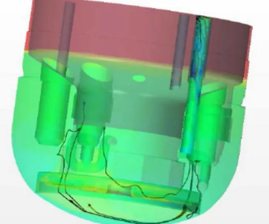
The RRA-DHX produces a downward cold-sodium column that dives through the cold pool and quickly reaches the bottom of the core-catcher. Fig 9 illustrates the cooled sodium path leaving the RRA-DHX. Path starts at the top of the RRA-DHX and plunge at the bottom of the cold pool, under the core catcher, where the cooling of the structure occurs. The re-heated sodium then ascends again. This convection loop provides the immediate surroundings of the core catcher with continuously flowing sodium. This confirms the satisfactory natural-convection behavior in the cold pool and especially around the core-catcher.
Fig. 9. Illustration of cold-sodium trajectory from the RRA DHX to the core catcher.
IV. CONCLUSIONS
Jointly developed by a French and Japanese design team, ASTRID decay heat removal systems are based on an adequate application of defense in depth principle with highlights by probabilistic assessment.
Diversification is the key point of ASTRID design with three types of systems in complement to the normal DHR system by ECS, which contribute to the robustness of the practical elimination demonstration. Option selection process of type of DHR systems and number of loops was also driven and confirmed by static probabilistic assessment
Among these systems, RRA located within the cold pool allows a significant level of diversification compared to RRB for both normal thermal loadings and severe accident consequences. Objective to reach a negligible level of creep damage within RRA system is pursued in order to confirm high level of temperature diversification. Several design options which are still considered to reach this target were described in this paper.
Also, CFD calculations confirmed that the RRA design is suitable for core catcher cooling capability. It is able to prevent immoderate increase of sodium temperature in the cold-pool and around the core catcher.
REFERENCES
1. J. ROUAULT et al. “ASTRID, The SFR GENIV Technology Demonstrator Project: Where Are We, Where Do We Stand For?”, Proceedings of ICAPP 2015, Nice, FRANCE, May 03-06, 2015
2. J. ROUAULT et al. “JAPAN-FRANCE collaboration on the ASTRID program and sodium fast reactor” Proceedings of ICAPP 2015, Nice, FRANCE, May 03-06, 2015
3. F. CURNIER et al. “Use of simplified PSA studies to support the ASTRID design process”. Proceedings of ICAPP 2014, Charlotte, USA, April 6-9, 2014. 4. F. CURNIER et al. “Symbiosis of static and dynamic
probabilistic approaches to support the design process and evaluate the safety of a SFR” Proceedings of PSA 2015, Sun Valley, USA, 26-30 April, 2015