Publisher’s version / Version de l'éditeur:
Vous avez des questions? Nous pouvons vous aider. Pour communiquer directement avec un auteur, consultez la première page de la revue dans laquelle son article a été publié afin de trouver ses coordonnées. Si vous n’arrivez pas à les repérer, communiquez avec nous à PublicationsArchive-ArchivesPublications@nrc-cnrc.gc.ca.
Questions? Contact the NRC Publications Archive team at
PublicationsArchive-ArchivesPublications@nrc-cnrc.gc.ca. If you wish to email the authors directly, please see the first page of the publication for their contact information.
https://publications-cnrc.canada.ca/fra/droits
L’accès à ce site Web et l’utilisation de son contenu sont assujettis aux conditions présentées dans le site LISEZ CES CONDITIONS ATTENTIVEMENT AVANT D’UTILISER CE SITE WEB.
SFPE-SAC Fire Science & Technology Conference [Proceedings], pp. 1-9,
2008-11-17
READ THESE TERMS AND CONDITIONS CAREFULLY BEFORE USING THIS WEBSITE. https://nrc-publications.canada.ca/eng/copyright
NRC Publications Archive Record / Notice des Archives des publications du CNRC : https://nrc-publications.canada.ca/eng/view/object/?id=f188441b-3d80-4e7f-bfca-fa0431b523c0 https://publications-cnrc.canada.ca/fra/voir/objet/?id=f188441b-3d80-4e7f-bfca-fa0431b523c0
NRC Publications Archive
Archives des publications du CNRC
This publication could be one of several versions: author’s original, accepted manuscript or the publisher’s version. / La version de cette publication peut être l’une des suivantes : la version prépublication de l’auteur, la version acceptée du manuscrit ou la version de l’éditeur.
Access and use of this website and the material on it are subject to the Terms and Conditions set forth at
The fire performance of FRP-strengthened concrete systems
Bénichou, N.; Green, M. F.; Bisby, L. A.; Chowdhury, R.; Williams, B. K.;
Kodur, V. K. R.
http://irc.nrc-cnrc.gc.ca
T h e f i r e p e r f o r m a n c e o f F R P - s t r e n g t h e n e d c o n c r e t e
s y s t e m s ( i n v i t e d p a p e r )
N R C C - 5 0 8 5 0
Bénichou, N.; Green, M.F.; Bisby, L.; Chowdhury, R.; Williams, B.; Kodur, V.R. énichou, N.; Green, M.F.; Bisby, L.; Chowdhury, R.; Williams, B.; Kodur, V.R.
2 0 0 8 - 1 1 - 2 6
A version of this document is published in / Une version de ce document se trouve dans:
SFPE-SAC Fire Science & Technology Conference, Al Khobar, Saudi Arabia, Nov. 17-18, 2008
The material in this document is covered by the provisions of the Copyright Act, by Canadian laws, policies, regulations and international agreements. Such provisions serve to identify the information source and, in specific instances, to prohibit reproduction of materials without written permission. For more information visit http://laws.justice.gc.ca/en/showtdm/cs/C-42
Les renseignements dans ce document sont protégés par la Loi sur le droit d'auteur, par les lois, les politiques et les règlements du Canada et des accords internationaux. Ces dispositions permettent d'identifier la source de l'information et, dans certains cas, d'interdire la copie de documents sans permission écrite. Pour obtenir de plus amples renseignements : http://lois.justice.gc.ca/fr/showtdm/cs/C-42
The Fire Performance of FRP-Strengthened Concrete Systems
Noureddine Benichou1, Mark Green2, Luke Bisby3, Ershad Chowdhury2, Brea Williams,
and Venkatesh Kodur4
1 BACKGROUND
Interest in the use of fiber-reinforced polymers (FRPs) in civil engineering applications has increased significantly in recent years. FRPs offer advantages, such as high strength and corrosion resistance over traditional materials such as concrete and steel. FRPs have been successfully used both as internal reinforcement and as externally-bonded reinforcement for reinforced concrete (RC) structures. As an external reinforcement, the use of FRP sheets or plates is now a method of choice for the rehabilitation and strengthening of concrete members in many cases. In these applications, FRPs are commonly wrapped around columns to increase their strength and ductility, or bonded to beams to improve flexure and/or shear capacity, slabs to improve flexural or punching capacity, or to strengthen structural connections.
At present, the use of FRPs is restricted primarily to bridge structures, where fire resistance is not a primary design consideration. However, there is enormous potential for the use of FRPs in buildings. Structural building members must be designed to satisfy appropriate fire resistance requirements in addition to other structural requirements specified in building codes. One of the main impediments to using FRPs in buildings is the lack of knowledge about the fire resistance of these systems. Before FRPs can be used with confidence in buildings, the performance of these materials under fire conditions, and the ability of structural members with which they are reinforced or strengthened to meet the fire resistance criteria set out in building codes, must be evaluated.
This paper presents the results of a collaborative investigation between the National Research Council of Canada (NRC), Queen's University through the Intelligent Sensing for Innovative Structures Canada (ISIS), and industry partners to study the structural fire resistance of FRP-strengthened concrete members under standard fire exposure. The following items will be presented: 1) some of the results of an experimental program, conducted at NRC, on FRP-strengthened RC columns, beams, and slabs exposed to standard fires; 2) the numerical fire simulation models that were developed to predict the heat transfer behavior and variation in load-carrying capacity of various types of insulated, uninsulated, FRP-strengthened, and unstrengthened RC members during exposure to standard fire scenarios; 3) the
recommendations for design guidelines for FRP-strengthened concrete structures in fire; and 4) a case study of the application of a fire-rated FRP system in a building.
2 FRP MATERIALS UNDER ELEVATED TEMPERATURES
FRP materials are sensitive at elevated temperatures. As the temperature of the polymer matrix
approaches its glass transition temperature, Tg, it transforms to a soft material with reduced
strength and stiffness. Common room-temperature cure thermoset polymer matrices used in
1 Fire Research Program, Institute for Research in Construction, National Research Council, Ottawa, Canada 2 Department of Civil Engineering, Queen’s University, Kingston, Canada
3 University of Edinburgh, Scotland, UK 4 Michigan State University, Michigan, USA
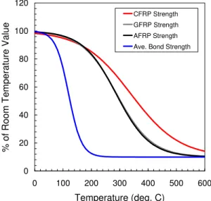
FRP strengthening of concrete structures, exhibit glass transition temperatures below 100°C. Under extreme heat, the polymer matrix may ignite, spread flames and produce toxic smoke. Figure 1 shows the approximate variation of ultimate tensile strength with temperature for glass and carbon FRPs, based on semi-empirical relationships from limited information reported in the literature. For FRP-strengthened RC members, where the FRP materials are typically bonded to the exterior of the RC structural members, no concrete cover is available for protection of the FRP reinforcement, and thus unprotected wraps can be expected to experience rapid
degradation of structural effectiveness almost immediately under exposure to a fire. However, because FRP materials are not usually used as primary reinforcement, loss of FRP
effectiveness during a fire may or may not be critical to ensure structural fire safety.
0 20 40 60 80 100 120 0 100 200 300 400 500 600 Temperature (deg. C) % o f Room Te mp era tur e Va lue CFRP Strength GFRP Strength AFRP Strength Ave. Bond Strength
Figure 1. FRP (Carbon, Glass and Aramid) properties at high temperature - FRP strength and bond strength to concrete (Y-axis is ratio of elevated temp. strength to room temp. strength)
3 FIRE RESISTANCE EXPERIMENTS
To study the performance of RC members strengthened with externally-bonded FRP systems during fire, a major experimental program was undertaken. Some of the test results are summarized in this section.
3.1 FRP-strengthened Concrete Slabs
As part of the development of insulation systems for FRP-strengthened structural systems, four intermediate-scale fire resistance experiments were conducted on reinforced concrete slabs strengthened with FRP sheets. Table 1 provides details of the slab specimens tested. The slabs were internally reinforced with conventional reinforcing steel, and were constructed from
carbonate aggregate concrete. The slabs were also protected with different supplemental fire insulation systems, applied to the exterior of the FRP wraps, and tested in fire according to ULC S101 [1] (similar to ASTM E119 [2]). All the insulation systems tested have proprietary spray-applied cementitous plasters developed by industry partners; see [3 and 4] for more information. The fire tests on the slabs have been used to evaluate the performance of the supplemental fire insulation systems and to provide insight into the appropriate insulation configurations and
thicknesses to be used when testing full-scale FRP-strengthened beams and columns. As such, the slabs were tested under self-weight only.
Overall, the slab tests have demonstrated that, according to thermal fire resistance criteria outlined in ULC S101 [1], a 4-h fire resistance rating can be achieved for an insulated FRP-strengthened concrete slab with a 38 mm of supplemental insulation applied to the exterior of the FRP wrap. A smaller thickness of insulation (19 mm) could provide 2 h of fire resistance. The tests also suggest that it will likely be very difficult to prevent the FRP temperature from
exceeding the Tg of the polymer matrix for more than 1 h, even with 38 mm of supplemental
insulation, and that providing sufficient insulation thickness is important in minimizing cracking and preventing possible delamination of the fire protection and FRP.
Table 1. Summary of results from fire tests Member Dimensions
(mm)
FRP Insulation Fire resistance
(min)
Failure Load or Moment
Slab 1 150 × 950 ×1330 1 layer - CFRP-A VG - 19 mm 147 NA
Slab 2 150 × 950 ×1330 1 layer - CFRP-A VG - 38 mm > 240 NA
Slab 3 150 × 950 ×1330 1 layer - CFRP-B Cem - 38 mm > 240 NA Slab 4 150 × 950 ×1330 1 layer - CFRP-B Cem - 38 mm > 240 NA Column 1 φ 400 × 3810 1 layer - CFRP-A VG - 32 mm > 300 4437 kN Column 2 φ 400 × 3810 1 layer - CFRP-A VG - 57 mm > 300 4680 kN
Column 3 φ 400 × 3810 2 layers - CFRP-B None 210 2635 kN
Column 4 φ 400 × 3810 2 layers - CFRP-B Cem - 53 mm > 300 4583 kN
T-beam 1 1 layer - CFRP-A VG - 25 mm > 240 142 kN.m
T-beam 2 1 layer - CFRP-A VG - 38 mm > 240 142 kN.m
T-beam 3 1 layer - CFRP-B Cem - 30 mm > 240 146 kN.m
T-beam 4 Length 3900 h = 400 hs = 150 bs = 1220 bw = 300 see Figure 4 1 layer - CFRP-B Cem - 28 mm > 240 120 kN.m
Notes: CFRP-A - tf = 1.0 mm per layer, ff = 745 MPa, εf = 0.012, Ef = 62 GPa, Tg = 93°C
CFRP-B - tf = 0.165 mm per layer, ff = 3800 MPa, εf = 0.0167, Ef = 227 GPa, Tg = 71°C
VG - gypsum-based insulation, thermal conductivity 0.082 W/m-ºC at room temperature Cem - cementitious insulation, thermal conductivity 0.37 W/m-ºC at room temperature
h = overall height of T-beam, hs = height of slab, bs = breadth of slab, bw = breadth of web
tf = thickness of one layer of FRP, ff = strength of FRP, εf = maximum strain at failure for FRP
Ef = modulus of elasticity of FRP, Tg = glass transition temperature of FRP, NA – not applicable 3.2 FRP-wrapped Concrete Columns
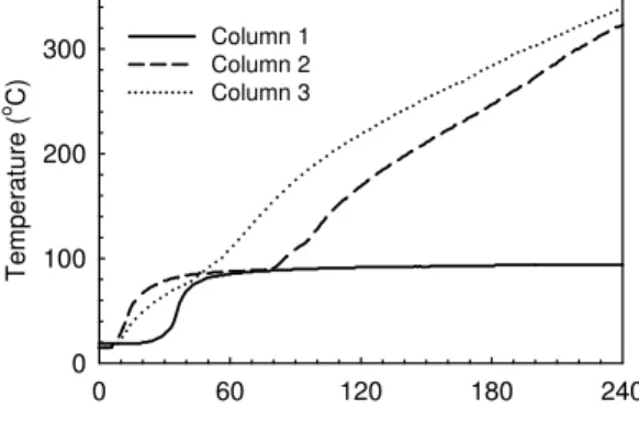
The column test program consisted of full-scale fire tests on four circular concrete columns, strengthened with carbon FRP wraps, and tested under full-sustained service load. All of the wraps were externally applied in the circumferential direction only. All columns were internally reinforced with conventional reinforcing steel. All, but one, of the columns were protected with supplemental insulation systems applied to the exterior of the FRP wrap. The same systems, used in the slab testing, were studied. Details of the columns tested are given in Table 1. Figure 2 shows temperatures recorded at the level of the FRP–concrete interface in three columns tested. The insulation provided good thermal protection for the columns as a whole,
even though the recorded FRP temperature exceeded Tg relatively early in the fire exposure for
all columns. Figure 3 shows a typical protected column immediately before fire testing and immediately after failure. The insulated column is visually in good condition after failure, and the fire insulation remained in-place even beyond failure. Failure of all columns appeared to be due
to crushing of the core concrete, with some evidence of buckling effects. It is important to recognize that, in general, the failure modes of the columns were typically sudden and accompanied by spalling of the concrete cover.
The uninsulated column also performed reasonably well during fire exposure and managed to sustain its required service load for about 3.5 h. However, the unprotected FRP-strengthening system burned within minutes of fire exposure and completely debonded from the column in less than 30 min. Clearly, the good performance of the column can be attributed to the fire resistance of the existing RC column – a result that demonstrates that loss of FRP effectiveness is not necessarily an appropriate failure criterion for fire resistant design of these members. The column tests have demonstrated that the unique insulation systems used are effective fire protection systems for FRP-wrapped reinforced concrete columns. The FRP-strengthened columns protected with these systems are capable of achieving satisfactory ULC S101 [1] fire
resistance ratings, in excess of 5 h, even when the FRPs’ Tg are exceeded early in the test. This
occurs because the preexisting unstrengthened concrete column, which is designed based on ultimate loads but subjected to service loads only during fire, is protected by the supplemental insulation system and experiences only mildly increased internal temperatures that do not significantly decrease its capacity during fire.
Time (minutes) 0 60 120 180 240 T e m perat ure ( o C) 0 100 200 300 Column 1 Column 2 Column 3
Figure 2. Temperature in the FRP for three of the columns
Figure 3. Typical circular column before and after fire testing
3.3 FRP-strengthened T-beams
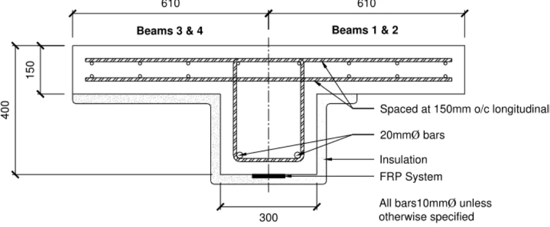
Four full-scale fire tests have been conducted on reinforced concrete T-beams that were strengthened in flexure with one layer of externally-bonded carbon FRP sheets on their soffits. To provide anchorage for the flexural sheets, FRP sheets were wrapped around the web in a U-shape at the ends of the beams. Figure 4 shows the details of the T-beam specimens, while Table 1 provides a summary of the fire tests conducted on these types of specimens. The T-beams were also protected with supplemental insulation around the web portion of the T-beams. The beams were tested under full-sustained service load according to ULC S101 guidelines [1]. In this case, all four beams were insulated. All of these beams achieved fire resistance ratings of over 4 hours. Figure 5 shows the temperatures at the FRP for all beams.
All bars10mmØ unless otherwise specified
All dimensions are in millimetres
Spaced at 150mm o/c longitudinally
20mmØ bars Insulation FRP System 15 0 40 0 300
Beams 3 & 4 Beams 1 & 2
610 610
Figure 4. Cross-sectional dimensions of the T-beams
Time (minutes) 0 60 120 180 240 T emp e rature ( o C) 0 200 400 600 800 1000 ULC S101 Beam 1 Beam 2 Beam 3 Beam 4 Insulation Delamination
Figure 5. Temperatures at the level of the FRP for all beams
Owing to limitations in the capacity of the loading system in the beam-slab test furnace, it was not possible to fail the insulated FRP-strengthened beam-slab specimens during the fire tests. Thus, after the beams had cooled to room temperature, they were tested for failure under monotonic load at room temperature. It was shown in these tests that the beams retained their full pre-fire predicted flexural strength. This testing suggests that appropriately fire insulated FRP-strengthened beams can retain their full unstrengthened capacity even after 4-h fire exposure. A second interesting implication of these results is the post-fire repairability of fire-damaged strengthened members. The results suggest that, for fire protected FRP-strengthened members, the post-fire capacity of the members is equivalent to the pre-fire capacity of the un-strengthened members. Thus, these members could be rewrapped after a severe fire and treated as essentially undamaged members.
4 NUMERICAL STUDIES
In addition to the experimental program, several numerical fire simulation models have been developed. The numerical models consist of finite difference heat transfer algorithms, coupled with structural analyses based on strain compatibility and force equilibrium. The models can predict the heat transfer behavior and variation in load-carrying capacity of insulated,
uninsulated, FRP-strengthened, and unstrengthened RC members during fire exposure. The models can account for a variety of factors in their analyses, including: magnitude of the sustained applied load; type of fire; specimen size and shape (rectangular or T-beams);
concrete aggregate type; concrete moisture content; steel reinforcement ratios and bar layouts; FRP type, width, and thickness; and insulation type, thickness, and configuration. The analyses can also account for debonding of the insulation and FRP at predefined times during fire.
In most cases, the models have been found to predict reasonably the heat transfer behavior and temperatures within insulated FRP-strengthened RC members, although the ability of the
models to predict temperatures near the Tg of the FRP polymer matrix requires some
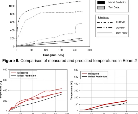
improvement. For example, Figures 6 and 7 show a comparison of the model prediction against temperatures measured for beams 1 and 2 during fire testing. More validation will be carried out to use the model with full confidence and to perform parametric studies that can provide design guidance to engineers to implement fire-safe FRP-strengthening systems.
Time [minutes] 0 60 120 180 240 300 ºC 0 200 400 600 800 1000 1200 Model Prediction Test Data EI-R/VG VG/FRP Steel rebar Interface:
Figure 6. Comparison of measured and predicted temperatures in Beam 2
Time [minutes] 0 60 120 180 240 300 T e m p er at ur e [º C] 0 200 400 600 800 Measured Model Prediction Time [minutes] 0 60 120 180 240 300 T e mperat ur e [º C] 0 100 200 300 400 500 600 Measured Model Prediction
a) FRP-concrete bond line for Beam 1 b) Steel reinforcement for Beam 2
Figure 7. Comparison of measured and predicted temperatures in Beams 1 and 2
5 DESIGN GUIDANCE
There is limited research on fire performance of FRP systems, and hence few rational guidelines currently exist for fire resistance design of FRP-reinforced structural systems.
In North America, structural members are required to carry their full service load for the required duration during fire. Until better information is available, FRP materials should be assumed ineffective during fire, and FRP-strengthened RC members should be designed such that the nominal strength during fire of the unstrengthened (preexisting) member remains greater than the strengthened (increased) service loads on the member for the required duration. A similar approach is currently suggested by Committee 440 of the American Concrete Institute [5], which suggests the following load limit for fire-safe design of FRP-strengthening systems:
(Rnθ)existing ≥ 1.0 SDL + 1.0 SLL (1)
(Rnθ)existing is the nominal strength of the un-strengthened member subjected to the elevated
temperatures associated with a fire and SDL and SLL represent the dead load and live load
effects acting on the strengthened structure. The above equation is essentially a statement of the ULC S101 [1] or ASTM E119 [2] load-bearing fire resistance criterion for columns, assuming that the loads acting on a structure during fire can reasonably be taken as the unfactored loads. Depending on the load and resistance factors used in design and the live-to-dead load ratio for the member being strengthened, increases in strength due to FRP wrapping must typically be limited to between about 25 and 70% based on fire-safety considerations.
While loss of effectiveness of the FRP during fire would likely cause a significant decrease in the ultimate strength of the member, this is not a problem provided that the preexisting member retains enough strength to carry its service loads.
The FRP strength could be relied on in a fire situation if and only if the temperature of the FRP is kept below some as yet unknown critical temperature. A conservative lower bound for the
critical temperature would be the Tg (typically below 100°C), and an upper bound would
probably be ~300°C for currently used epoxy adhesives [6].
For FRP-strengthened RC members that are protected with supplemental fire insulation, the insulation allows the members to retain much of their pre-fire strength, even after exposure to the standard fire for more than 4 h, and even if the FRP is rendered ineffective.
The experiments conducted here have resulted in the development of fire resistance ratings for insulated FRP-strengthened columns and beam-slab assemblies. Based on the test results, standard fire ratings have been developed for the specific insulated FRP-strengthened beam-slab assemblies and columns tested, and these rated assemblies are listed in [7 and 8].
6 FIELD APPLICATION
The fire resistance ratings for FRP-strengthened concrete members described above have been instrumental in enabling the application of these types of systems in field applications. One such field application is a large section of a concrete slab roof in a manufacturing plant in Denver, CO, USA, that was damaged by a severe fire which led to a significant reduction in the load-carrying capacity and allowable fire rating of the roof slab assembly. The repair options
available to the owner were rehabilitation using FRP sheets or removal and replacement of the concrete slabs. Through consultations and in order to minimize downtime for the company, the
owner selected a rehabilitation scheme using an externally-bonded FRP system. The slab rehabilitation was accomplished by applying an externally-bonded FRP-strengthening system to both faces of the roof slabs, a steel mesh was mechanically attached to the underside of the slab, and subsequently a cementitious fireproofing material spray-applied to achieve the required fire rating. The existing concrete cover on the underside of the roof slab was removed and replaced prior to strengthening of the slab with the FRP system. The resulting insulated FRP-strengthening system gave a minimum 1-h fire rating.
7 CONCLUSIONS
FRP-strengthened RC systems (columns, beams, and slabs), protected with the fire protection system, are capable of achieving satisfactory fire resistance ratings according to ULC S101 requirements, under full service loads. The fire performance of insulated FRP-strengthened systems can be similar to, or better than, that of conventional reinforced concrete members.
Even though the glass transition temperature (Tg) of the FRP polymer matrix was exceeded
relatively earlier in the fire exposure, all tested insulated FRP-strengthened concrete members have achieved satisfactory fire resistance, These results suggest that the fire resistance for FRP-strengthened concrete members should not be defined in terms of temperatures at the level of the FRP, but rather, should be based on the load-carrying capability of the structural
systems during fire. Thus, reaching the matrix Tg of an externally-bonded FRP system during
fire does not necessarily indicate failure of the FRP-strengthened concrete member.
The guidelines presented in this article can be used as guidance for achieving an appropriate level of fire safety for a given FRP-strengthened RC member. However, additional information is required on the specific performance of FRP materials and externally-bonded FRP systems at elevated temperatures, such that critical temperatures can be defined for these systems.
8 REFERENCES
1. CAN/ULC, ‘‘Standard Methods of Fire Endurance Tests of Building Construction and Materials,’’ CAN/ULC-S101-07, Underwriters’ Laboratories of Canada, Scarborough, ON, Canada, 2007
2. ASTM, Test Method E119-08: Standard Methods of Fire Test of Building Construction and Materials, American Society for Testing and Materials, West Conshohocken, PA, USA, 2008.
3. Bisby, L.A., ‘‘Fire Behaviour of FRP Reinforced or Confined Concrete,’’ PhD Thesis, Department of Civil Engineering, Queen’s University, Kingston, ON, Canada, 2003. 4. Bisby, L.A., Green, M.F. and Kodur, V.K.R., ‘‘Fire Endurance of FRP-Confined Concrete
Columns,’’ ACI Structural Journal, Vol. 10, No. 6, 2005, pp. 883–891.
5. ACI, 440.2R-02: Guide for the Design and Construction of Externally Bonded FRP Systems for Strengthening Concrete Structures, American Concrete Institute, Farmington Hills, MI, USA, 2002.
6. Foster, S.K. and Bisby, L.A., ‘‘High Temperature Residual Properties of Externally bonded FRP Systems,’’ FRPRCS-7, New Orleans, November 7–10, 2005.
7. UL, Fire Resistance Ratings – ANSI/UL 263, Design No. N790, Underwriters Laboratories Inc., Northbrook, IL, USA, 2004.
8. UL, Fire Resistance Ratings – ANSI/UL 263, Design No. X842, Underwriters Laboratories Inc., Northbrook, IL, 2004.
9 ACKNOWLEDGEMENTS
This research was funded by the National Research Council (NRC), the Intelligent Sensing for Innovative Structures (ISIS Canada) Research Network of Centres of Excellence, the Natural Sciences and Engineering Research Council of Canada (NSERC), and industry partners Fyfe, BASF/Degussa, and Sika. The authors would also like to acknowledge the contributions of the technical staff at NRC and Queen’s University.