Publisher’s version / Version de l'éditeur:
Proceedings of 12th CANSMART International Workshop on Smart Materials and Structures, pp. 217-226, 2009-01-01
READ THESE TERMS AND CONDITIONS CAREFULLY BEFORE USING THIS WEBSITE. https://nrc-publications.canada.ca/eng/copyright
Vous avez des questions? Nous pouvons vous aider. Pour communiquer directement avec un auteur, consultez la
première page de la revue dans laquelle son article a été publié afin de trouver ses coordonnées. Si vous n’arrivez pas à les repérer, communiquez avec nous à PublicationsArchive-ArchivesPublications@nrc-cnrc.gc.ca.
Questions? Contact the NRC Publications Archive team at
PublicationsArchive-ArchivesPublications@nrc-cnrc.gc.ca. If you wish to email the authors directly, please see the first page of the publication for their contact information.
NRC Publications Archive
Archives des publications du CNRC
This publication could be one of several versions: author’s original, accepted manuscript or the publisher’s version. / La version de cette publication peut être l’une des suivantes : la version prépublication de l’auteur, la version acceptée du manuscrit ou la version de l’éditeur.
Access and use of this website and the material on it are subject to the Terms and Conditions set forth at
High temperature flexible ultrasonic transducers for structural health monitoring and NDT
Shih, J.-L.; Kobayashi, M.; Jen, C.-K.; Tatibouët, J.; Mrad, N.
https://publications-cnrc.canada.ca/fra/droits
L’accès à ce site Web et l’utilisation de son contenu sont assujettis aux conditions présentées dans le site LISEZ CES CONDITIONS ATTENTIVEMENT AVANT D’UTILISER CE SITE WEB.
NRC Publications Record / Notice d'Archives des publications de CNRC:
https://nrc-publications.canada.ca/eng/view/object/?id=880b0010-35fd-49a0-a18f-29532d75e4a4 https://publications-cnrc.canada.ca/fra/voir/objet/?id=880b0010-35fd-49a0-a18f-29532d75e4a4
Cansmart 2009
International Workshop
SMART MATERIALS AND STRUCTURES
22 - 23 October 2009, Montreal, Quebec, Canada
HIGH TEMPERATURE FLEXIBLE ULTRASONIC TRANSDUCERS FOR STRUCTURAL HEALTH MONITORING AND NDT
J.-L. Shih1, M. Kobayashi2, C.-K. Jen2 , J. Tatibouët2 and N. Mrad3
1
Department of Electrical and Computer Engineering, McGill University Montreal, Quebec, Canada H3A 2A7
jeanne-louise.shih@imi.cnrc-nrc.gc.ca
2
Industrial Materials Institute, National Research Council, Boucherville Quebec, Canada J4B 6Y4
makiko.kobayashi@cnrc-nrc.gc.ca; cheng-kuei.jen@cnrc-nrc.gc.ca
3
Department of National Defense, Defense R&D Canada, Air Vehicles Research Section, National Defense Headquarters, Ottawa, Ontario, Canada K1A 0K2
Nezih.Mrad@drdc-rddc.gc.ca
ABSTRACT
Flexible ultrasonic transducers (FUTs) consisting of a 75 μm thick metal membrane, a
piezoelectric composite with a thickness larger than 85 μm and a top electrode were developed
for structural health monitoring (SHM) and non-destructive testing (NDT) applications. The piezoelectric films were made by a sol-gel spray technique. Its ultrasonic performance in terms of signal strength is at least as good as commercially available broadband ultrasonic transducers at room temperature. Onsite gluing and brazing installation techniques which bond the FUTs onto steel pipes for SHM and NDT purposes up to 100°C and 150°C are developed, respectively. The best thickness measurement accuracy of FUT at 150°C was estimated to be 26 μm.
Keywords: Flexible ultrasonic transducer, High temperature, Thick piezoelectric film, Non-destructive testing, Structural health monitoring, Brazing.
INTRODUCTION
The non-destructive testing (NDT) of pipes in nuclear and fossil fuel power plants [1-3], chemical and petroleum plants [1, 2] and other structures [4] has become an increasingly important element in the improvement of safety and in the extension of a structure’s life span. Structural health monitoring (SHM) [5, 6] is a furtherance of the NDT approach. Ultrasonic techniques are frequently used for these NDT and SHM purposes because of their subsurface inspection capabilities, fast inspection speeds, simplicity and ease of operation. In these applications, ultrasonic transducers (UTs) may need to be made directly in contact with structures that have surfaces with different curvatures and must also be able to operate at elevated temperatures. However, conventional UTs having rigid flat end surfaces may in general show poor performance and therefore may not be readily suitable for the inspection of pipes at elevated temperatures. The poor signal-to-noise ratio (SNR) may in part come from the fact that the contacting area is a narrow line allowing only a small portion of the available ultrasonic energy to be transmitted into the pipe. Different thicknesses in gel couplant that are present in the gap area between the UT flat end surface and the curved surface of the pipe cause the areas other than this narrow contact line of the UT to generate many unwanted noises. Flexible UTs (FUTs) are therefore more suitable under such conditions because they ensure their self-alignment to the object’s surface even in the case of a curved or complex geometry so that the transmitted ultrasonic energy may be maximized and noises may be minimized to improve SNR for NDT or SHM purposes [7 - 9].
In commercially available FUTs, piezoelectric polymers such as polyvinylidene fluoride (PVDF) [8] and piezoelectric ceramic/polymer composites [8, 10] are mainly used as piezoelectric materials. Both materials include polymer, which prevents the use of such flexible UTs at elevated temperatures. Other flexible, high temperature ultrasonic transducers (HTUTs) have also been reported [11]. In order to provide flexibility for the single crystal films used, the
thickness of the piezoelectric films were thin, from 0.2 to 10 μm. Thus operating frequencies
were normally higher than 30 MHz and these may not be suitable for NDT and SHM of thick and highly attenuating materials.
The objective of this investigation was to develop FUTs that have high flexibility similar to PVDF FUTs [7], but can operate at up to at least 150°C and have a high ultrasonic performance comparable to commercial broadband UTs. In addition to the use of a high temperature couplant for momentary contact NDT, a gluing and a brazing onsite installation technique will be investigated for permanent NDT or SHM over curved surfaces such as on steel pipes and at temperature up to 150°C. The glue and the brazing material between the FUT and the external surface of the pipe serves as a permanent high temperature couplant.
FABRICATION AND PERFORMANCE OF FUT
Fabrication procedures
The fabrication of the FUT consists of a sol-gel based sensor fabrication process [12]. The
substrate can be a 75 μm thick titanium (Ti) or stainless steel (SS) membrane. Such an approach
consists of six main steps [9, 13]: (1) preparing a high dielectric constant lead-zirconate-titanate (PZT) solution, (2) ball milling the piezoelectric PZT powders in a PZT solution to submicron
sizes. In this case, PZT powders were selected because of their high piezoelectric strength and Curie temperature of 350°C. (3) sensor spraying using slurries from steps (1) and (2) to produce
a film with thicknesses of between 5 and 20 μm, (4) heat treating to produce a solid PZT
composite (PZT-c) thick film, (5) Corona poling to obtain piezoelectricity, and (6) silver paste painting for depositing electrical connections. Steps (3) and (4) are performed multiple times to produce optimal film thicknesses for specified ultrasonic operating frequencies. In this investigation, steps (4) and (5) are significantly different from the FUT processes presented in [9]. Here a rapid thermal annealing like process [14 - 16] was used for the thermal treatment. The main advantage of rapid thermal annealing is to limit the eventual degradation of the film-substrate interface such as through inter-diffusion of lead and also to improve the crystallization behavior of the PZT film. The short annealing time also avoids the growth of an oxidation layer between the Ti or SS and PZT-c film. An oxidation layer would reduce the electrical conductivity of Ti and SS, thereby decreasing the ultrasonic performance. In this study longitudinal (L) ultrasonic wave transducers are described. The relative dielectric constant was calculated using the capacitance measured by an impedance analyzer.
Performance of FUT
Firstly, an FUT was made with a ~120 μm thick PZT-c film that was deposited onto a 75 μm
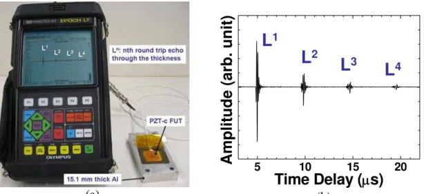
thick Ti membrane. It is noted that the ultrasonic performance of such FUTs on Ti membranes showed in general a 5 dB stronger signal strength than those reported in [9], whereby FUTs were made onto SS membranes. The improved signal strength comes from the reduced oxidation of the membrane substrates (Ti over SS) during heat treatments and improvement of the sol gel spray technique. The FUT was attached to a 15.1 mm thick aluminum (Al) plate using a gel couplant as shown in Fig. 1a. The pulse-echo measurement was carried out by a handheld EPOCH model LT pulser/receiver (from Olympus-Panametrics, USA) at room temperature. The EPOCH LT is commonly used for NDT in industrial environments. The diameter of the top silver paste electrode of this FUT was 7 mm, which was the size required to match the electrical impedance of the PZT-c film with that of the pulser/receiver and to achieve maximum signal strength in pulse-echo mode at room temperature. The measured ultrasonic
data in pulse-echo mode is shown in Fig. 1b, where Ln is the nth trip L echo through the plate
thickness. The center frequency and the 6 dB bandwidth of L1 echo are 8.1 MHz and 5.3 MHz
respectively. In Fig. 1b, 0 dB gain out of the available 100 dB receiver gain of EPOCH was
used. The SNR of the L1 echo is ~38dB. The SNR is defined as the ratio of the amplitude of the
fist echo (here L1) over that of the surrounding noise. For comparison, Figs 2a and 2b show
measured results obtained when commercial broadband UTs with a center frequency of 5 MHz and 10 MHz, respectively, were used at the other side of the Al plate shown in Fig. 1a together with the same gel couplant. The receiver gains used by the EPOCH pulser/receiver were 2 dB and 2 dB, respectively. These results show that while using the EPOCH, the signal strength of the FUT was at least as good as those of the two commercially purchased broadband UTs.
(a)
5 10 15 20
Amplit
ude (arb. unit)
Time Delay (
μ
s)
L
1L
2L
3L
4 (b)Fig. 1: (a) Measurement setup for a FUT made of PZT-c film attached to an Al plate using an EPOCH LT in pulse-echo mode; (b) Measured ultrasonic signals at room temperature.
L
1L
2L
3L
45 10 15 20
Amplitude (arb. unit)
Time Delay (
μ
s)
(a)L
1L
2L
3L
4 5 10 15 20A
m
pl
it
ude (
a
rb.
uni
t)
Time Delay (
μ
s)
(b)Fig. 2: Measured ultrasonic signals from commercial UTs with a center frequency of (a) 5 MHz and (b) 10 MHz operated in pulse/echo mode at the opposite surface of the Al plate.
ULTRASONIC THICKNESS MEASUREMENTS OF PIPES AT ELEVATED TEMPERATURES
Momentary NDT with FUT
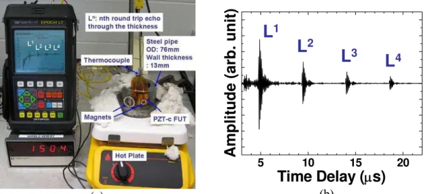
Developed FUTs can be operated in pulse-echo, pitch-catch and transmission configurations. Fig. 3a shows a magnet holder that was used to attach a FUT to a steel pipe with an outer diameter (OD) of 76 mm and an inner diameter (ID) of 50 mm at 150°C. The thickness of the pipe was 13 mm. The temperature was achieved with a hot plate and was controlled by the monitoring of a thermocouple in contact with the pipe. Oil was used as the ultrasonic couplant between the FUT and the external surface of the pipe. A momentary contact method such as the example given here is often used during NDT applications. The same FUT together
with the holder can be used at different locations. The FUT had a 95 µm thick PZT-c film and the diameter of the top silver paste top electrode was 5 mm. Fig. 3b shows the measured
ultrasonic signal, where Ln is the signal traveling through the thickness for the nth time. The 5
mm top electrode diameter was chosen not to achieve maximum signal strength, but rather to
achieve maximum SNR of the L1 for thickness measurement. The center frequency and the 6
dB bandwidth of the L1 echo were 10.9 MHz and 2.9 MHz, respectively. For this measurement,
the holding of the FUT onto the steel pipe was using a magnet as shown in Fig.3a. A gain of 52 dB was used out of the available 100 dB gain provided by the EPOCH LT. The high 52 dB gain may be explained by the presence of the oil couplant, the 150°C high temperature, not optimized top electrode diameter, the insufficient contact force applied to the FUT and the
ultrasonic attenuation within the thickness of the pipe wall. The SNR of L1 is ~24 dB. The
measurement confirms that such a FUT is useful for thickness measurements of a pipe at up to at least 150°C. Certainly if there is a defect existing within the 13 mm thickness of the pipe under the top electrode, NDT of the said defect may be achieved. If the thickness of the pipe is thin enough compared to the wavelength, such a FUT may be able to generate and receive guided waves along the pipe.
(a)
L
1L
2L
3L
4 5 10 15 20Amplitude (
a
rb. unit
)
Time Delay (
μ
s)
(b)Fig. 3: (a) A FUT is attached onto a steel pipe by a magnet holder and operated at 150°C and (b) shown is its measured ultrasonic signals in pulse-echo mode.
Permanent NDT with glued FUT
In certain situations, NDT of pipes must be carried out continuously. The momentary contact approach presented in the previous section may not be appropriate; therefore a onsite gluing technique is performed. Let FUT consisting of a 75 µm thick Ti membrane, a 85 µm thick PZT-c film, a 5 µm thick silver paste was made, glued onto a steel pipe, and heated by a hot plate up to ~100°C as shown in Fig. 4a using a glue which can be cured at room temperature. The pipe was first washed with water, soap and methanol. A thin layer of glue was then deposited on the backside of the FUT. It is then clamped onto the cleaned pipe using a metallic worm clamp and a SS plate that is conformed over the FUT and onto the curvature of the pipe. The OD and the wall thickness of the pipe are 89 mm and 6.5 mm, respectively. In Fig. 4a, there are two top electrodes and each of them serves as one FUT. Using one of the two FUTs the ultrasonic measurement was performed by a handheld EPOCH LT pulser/receiver
together with two spring electrical contacts of which one connects to the top silver paste
electrode and one to the bottom electrode which is the Ti membrane. Ln is the nth round trip
ultrasonic echoes within the wall thickness of the pipe. The pulse energy used was the lowest available and the gain was 5 dB out of the available 100 dB at 100°C.
(a) 2 4 6 8 10 Amplitude (ar b. unit) Time Delay (μs) at room temp. L4 L3 L2 L1 at 100°C (b)
Fig. 4: (a) A FUT fabricated on a 75 µm thick Ti membrane and glued onto a steel pipe with the ultrasonic measurements displayed using a handheld EPOCH LT pulser/receiver (b)
Measurement results obtained at room temperature (upper trace) and 100°C (lower trace).
Fig. 4b shows the pulse/echo measurement results obtained at room temperature (upper
trace) and 100°C (lower trace). The center frequency and 6 dB bandwidth of the L1 echo of the
lower trace were 11.9 MHz and 4.1 MHz, respectively. The signal strength of the L1 echo
obtained at 100°C (lower trace) reduces only about 1 dB comparing to that obtained at room temperature. The onsite installation of FUTs using glue cured at room temperature is therefore suitable for SHM of pipes within this temperature range.
Permanent NDT with brazing FUT
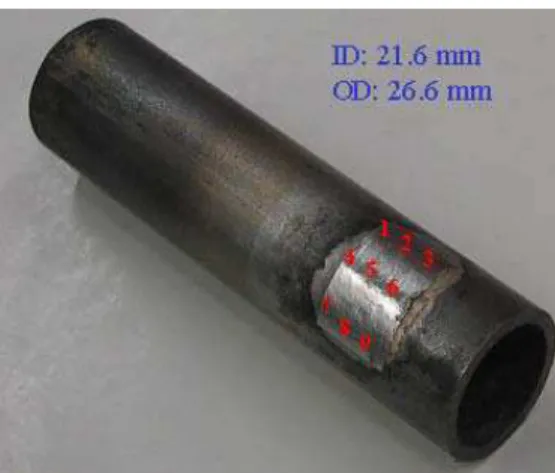
Also for permanent NDT and SHM another onsite installation technique using brazing was also performed. Fig. 5 shows a 15 mm wide and 23 mm long 75 µm thick SS membrane which is brazed onto a steel pipe with an OD of 26.6 mm and pipe wall thickness of 2.5 mm. For brazing 75 µm SS rather than Ti membrane was selected for FUT due to its ability to be brazed onto steel pipes with a small compromise to be made with respect to the minor level of oxidation that develops on the SS membrane during heat treatments. The developed onsite installation approach for brazing the FUT onto steel pipes is also simple and easy to follow. Similar to the gluing technique the pipe was first washed with water, soap and ethanol and a thin layer of brazing paste was then deposited on the backside of the FUT as evenly as possible. The FUT is then clamped onto the cleaned pipe using a metallic worm clamp and a SS plate that is conformed over the FUT and onto the curvature of the pipe. The induction heating system was calibrated to maximize the power and frequency of the system and it was controlled by a two-color pyrometer. The induction lasted three minutes and the temperature required was 825 °C for this SS substrate FUT to be brazed onto the steel pipe. After the induction, Corona poling was used to make the film piezoelectric. The developed Corona poling method is a convenient method to pole the FUT that has been brazed onto curved pipes. After poling, a silver paste was used to deposit the top electrode of necessary size.
Fig. 5: Brazed FUT SS membrane substrate on the external surface of a steel pipe where the ID
and the OD of the steel pipe are shown.
Table 1 demonstrates the coupling efficiency of the brazing material existing between the SS membrane and the external surface of the pipe under the SS membrane. It was measured with a commercial broad bandwidth UT centered at 10 MHz. Let us assume that 0 dB is the coupling efficiency of a commonly used gel couplant between a UT and the pipe. The amount of dBs appearing in nine measurement points on the pipe proves that the brazing material between the SS membrane and the external surface of the pipe was uniform and that the average loss was about 5 dB. Fig. 6a shows a FUT brazed onto this pipe and the measurement results taken at 150°C are presented in Fig. 6b. The gain used with the EPOCH was 20 dB out of the available 100 dB. This FUT had a 113 µm thick PZT-c film and the diameter of the top silver paste top electrode was 2.5 mm. The 2.5 mm was chosen not to achieve maximum signal
strength, but rather to achieve maximum SNR of the L1 for thickness measurement.
Spring-loaded pins, one of which was connected to the top electrode and the other, connected to the grounded steel pipe, served as the electrical contact. The 20 dB gain may be explained by the presence of the brazing material, the 150°C high temperature, not optimized top electrode diameter and the ultrasonic attenuation within the thickness of the pipe wall. Fig. 5b indicates that the brazing technique uniquely used for such a FUT is an excellent approach to bond a FUT to a pipe with an OD of 26.6 mm for NDT or SHM measurements performed at up to at least 150°C.
Table 1: Ultrasonic coupling efficiency of brazing material. Position of
brazed SS Coupling efficiency (dB)
1 4 2 6 3 4 4 3 5 5 6 3 7 6 8 6 9 6
Brazed PZT/PZT FUT Pipe Arm heater Spring contacts L2 L4 L6 Ln: nth round trip echo through the thickness Ln: nth round trip echo through the thickness Brazed PZT-c FUT Pipe Arm heater Spring contacts L1 L2 L3 n L :nth round trip echo through the thickness Brazed PZT/PZT FUT Pipe Arm heater Spring contacts L2 L4 L6 Ln: nth round trip echo through the thickness Ln: nth round trip echo through the thickness Brazed PZT-c FUT Pipe Arm heater Spring contacts L1 L2 L3 n L :nth round trip echo through the thickness (a) 2 4 6 8 L5 L4 Am p li tu de ( a rb. uni t) Time delay (µs) L2 L3 L1 (b)
Fig. 6: (a) A FUT brazed onto a steel pipe and (b) ultrasonic measurement through thickness at 150°C.
Thickness measurement accuracy
Equation (1) (Equation 19 in [17]) is used here for the estimation of the measurement accuracy for time delay and then that for thickness of the steel pipe shown in Fig. 6a.
(
)
(
)
⎟⎟ ⎠ ⎞ ⎜ ⎜ ⎝ ⎛ − ⎟⎟ ⎠ ⎞ ⎜⎜ ⎝ ⎛ + ⎟⎟ ⎠ ⎞ ⎜⎜ ⎝ ⎛ + + ≥ Δ − Δ 1 1 1 1 1 1 12 2 3 ' 2 2 2 1 2 3 2 3 0 T B B SNR SNR f t t ρ π σ (1)Table 2: Parameters for Equation 1 and digitization resolution
Parameters Values for the brazed FUT
on steel pipe ƒ0 10.8 MHz T 0.88 µs B 0.32 ρ 0.91 SNR1 26 dB SNR2 20 dB ) (Δt−Δt) σ 2.66 ns
Digitization resolution (100 MHz) including
interpolation 2 ns
Total time delay uncertainty 4.66 ns
VL 5682 m/s
Thickness measurement accuracy 26 µm
In this equation, f is the center frequency, T is the time window length for the selection of
L1 and L2 in Fig. 6b that is required for the cross correlation measurement, B is the fractional
bandwidth of the signal which is the ratio of the signal bandwidth over f , ρ is the correlation
coefficient, SNR and SNR are the SNR of the 1st echo and 2nd echo respectively, and ρ(∆t -
∆t’) is the standard deviation of the measured time delay (∆t being the true time delay and ∆t’,
the estimated time delay). Using Equation 1, the calculated ρ (∆t - ∆t’) was 2.66 ns. Since a
sampling rate of 100 MHz was used in the experiment, with the use of the cross correlation 0
0
method including interpolation [18], the time measurement error, which may be additionally introduced, was estimated to be 2 ns. The total uncertainty in time delay measurement was therefore 4.66 ns. Since the measured longitudinal velocity V in the steel substrate using the pulse-echo technique at 150°C was 5682 m/s, the best possible thickness measurement accuracy achievable using the above parameters given in Table 2 was 26 µm in pulse/echo mode at 150°C. If the sampling rate is increased to more than 100 MS/s, improved thickness measurement accuracy may be obtained.
L
CONCLUSIONS
Flexible ultrasonic transducers (FUTs) consisting of a 75 µm thick metal membrane, a piezoelectric PZT composite with a thickness larger than 85 µm and a top electrode were developed for NDT and/or SHM applications. The piezoelectric films were made by a sol-gel spray technique together with rapid thermal annealing. The main advantage of rapid thermal annealing is to limit the eventual degradation of the film-substrate interface such as through inter-diffusion of lead and also to improve the crystallization behavior of the PZT film. The short annealing time also prevents oxidation between the Ti or SS and PZT-c film of the FUT. An oxidation layer would reduce the electrical conductivity of Ti and SS, which would decrease the ultrasonic performance. In this study, the ultrasonic performances in terms of signal strength of a FUT were at least as good as commercially available 5 MHz and 10 MHz broadband ultrasonic transducers at room temperature. One FUT developed was used for pipe thickness measurements at 150°C using momentary contact with a high temperature ultrasonic couplant. The onsite installation gluing and brazing techniques were used to glue or braze a FUT to a steel pipe to serve NDT and/or SHM applications such as the monitoring of erosion and corrosion of the inner pipe surfaces. The Corona poling method was conveniently applied to the FUT after the brazing technique. At 150°C the best possible thickness measurement accuracy was estimated to be 26 µm for a steel pipe with a 26.6 mm outer diameter and a thickness of 2.5 mm.
ACKNOWLEDGMENT
Financial support of J.-L. Shih from the Natural Sciences and Engineering Research Council of Canada and the technical assistance of J.-F. Moisan are acknowledged.
REFERENCES
1. Birks, A.S., Green, R.E. Jr. and McIntire, P., Nondestructive Testing Handbook, 2nd ed., vol.7: Ultrasonic Testing, ASNT, 1991, pp.569-587.
2. Moore, P.O., Workman, G.L. and Kishoni, D., Nondestructive Testing Handbook, 3rd ed., vol.7: Ultrasonic Testing, ASNT, 2007, pp.427-474.
3. Kazys, R., Voleisis, A., Sliteris, R., Mazeika, L., Van Nieuwenhove, R., Kupschus, P. and Abderrahim, H.A., “High temperature ultrasonic transducers for imaging and measurements in a liquid Pb/Bi eutectic alloy”, IEEE Trans. UFFC, vol.52, no. 4, 2005, pp. 525-537. 4. Kelly, S.P., Atkinson, I., Gregory, C. and Kirk, K.J., “On-line ultrasonic inspection at
elevated temperatures”, Proc. IEEE Ultrasonics Symp., 2007, pp. 904-908.
5. Gandhi, M.V. and Thompson, B.S., “Smart Materials and Structures”, Chapman & Hall, NY, 1992.
6. Ihn, J.-B. and Chang, F.-K., “Ultrasonic non-destructive evaluation for structure health monitoring: built-in diagnostics for hot-spot monitoring in metallic and composite structures”, Chapter 9 in Ultrasonic Nondestructive Evaluation Engineering and Biological Material Characterization, edited by Kundu T., CRC Press, NY, 2004.
7. Wang, D. H. and Huang, S.L., “Health monitoring and diagnosis for flexible structures with PVDF piezoelectric film sensor array”, J. Intelligent Mat. Systems and Structures, vol. 11, 2000, pp. 482-491.
8. Devallencourt, C., Michau, S., Bantignies, C. and Felix, N., “A 5 MHz piezocomposite ultrasound array for operations in high temperature and harsh environment”, Proc. IEEE Ultrason. Symp., 2004, pp. 1294-1297.
9. Kobayashi, M., Jen, C.-K. and Lévesque, D., “Flexible ultrasonic transducers”, IEEE Trans. UFFC, vol.53, 2006, pp.1478-1485.
10. Parr, A.C.S., O’leary R.L. and Hayward, G., “Improving the thermal stability of 1-3 piezoelectric composite transducers”, IEEE Trans. UFFC., vol. 52, no. 4, 2005, pp. 550-563.
11. Akiyama, M., Kamohara, T., Nishikubo, K., Ueno, N., Nagai, H. and Okutani, T., “Ultrahigh temperature vibration sensors using aluminum nitride thin films and W/Ru multilayer electrodes”, Appl. Phys. Lett., vol. 86, 2005, 022106 (3 pages).
12. Barrow, D.A., Petroff, T.E., Tandon, R.P. and Sayer, M., “Characterization of thick lead zirconate titanate films fabricated using a new sol gel based process”, J. Appl. Phys., vol.81, 1997, pp. 876-881.
13. Kobayashi, M. and Jen, C.-K., “Piezoelectric thick bismuth titanate/PZT composite film transducers for smart NDE of metals”, Smart Materials and Structures, vol.13, 2004, pp.951-956.
14. Velu, G., Remiens, D. and Thierry, B., “Ferroelectric properties of PZT thin films prepared by sputtering with stoichiometric single oxide target: comparison between conventional and rapid thermal annealing”, J. European Ceram. Soc., vol. 17, pp. 1949-1955, 1997.
15. Hu, H., Peng, C.J. and Krupanidhi, S.B., “Effects of heating rate on the crystallization behaviour of amorphous PZT thin films”, Thin Solid Films, vol.223, 1993 pp. 327-333. 16. Lu, J., Zhang, Y., Ikehara, T., Maeda, R. and Mihara, T., “Effects of rapid thermal
annealing on nucleation, growth, and properties of lead zirconate titanate films”, IEEE Trans. UFFC, vol.54, no. 12, 2007, pp. 2548- 2554.
17. Walker, W.F. and Trahey, G.E., “A fundamental limit on delay estimation using partially correlated speckle signals,” IEEE Trans. UFFC, vol.42, no. 2, 1995, pp.301-308.
18. Aussel, J.-D. and Monchalin, J.-P., “Precision laser-ultrasonic velocity measurement and elastic constant determination,” Ultrasonics, vol. 27, 1989, pp.165-177.